Table of Contents
Advertisement
Available languages
Available languages
Quick Links
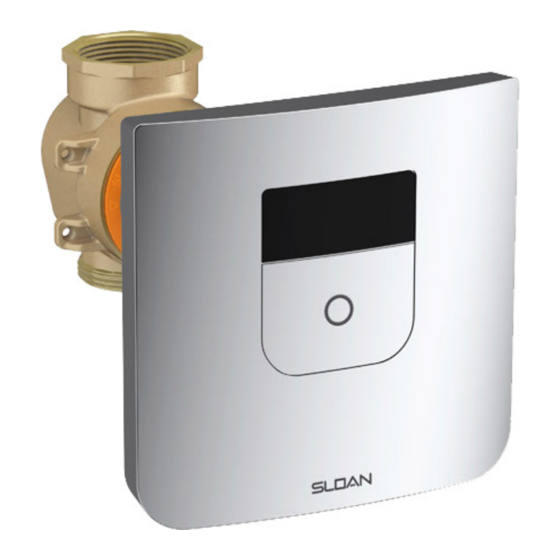
TRUFLUSH ELECTRONIC CLOSET AND URINAL FLUSHOMETERS
PRIOR TO INSTALLATION
his valve is designed for new construction or where there is easily
T
accessed plumbing for the fixture and the valve.
This valve is designed for minimum six inch (152 mm) wall space
depth. Distance from center of the valve (inlet or outlet pipe) to the
finished surface of the wall can vary from 2"-3" (51-76 mm).
TOOLS REQUIRED FOR INSTALLATION
• Smooth-jawed wrench (at least 2") • Phillips screwdriver • 5/64" hex wrench (supplied) • Adjusting tool (supplied) • Flathead screwdriver .118"
(3 mm or below) • Wire stripper tool
ROUGH-IN
2" (51 mm) MINIMUM
3" (76 mm) MAXIMUM
C.L. TO FINISHED WALL
1 1/2" NPT
INLET
2.0" - 2.4"
(50 mm - 60 mm)
1 1/2"
OUTLET
18"
Toilet Seat
(457 mm)
(not supplied)
Finished Wall
CLOSET
INSTALLATION INSTRUCTIONS FOR
TruFlush Models:
TRF 8156-1.6
TRF 8156-1.28
TRF 8196-0.5
TRF 8196-0.25
1 1/2" NPT
INLET
1 1/2"
OUTLET
Finished Floor
URINAL
LIMITED WARRANTY
Unless otherwise noted, Sloan Valve Company warrants this product,
manufactured and sold for commercial or industrial uses, to be free
from defects in material and workmanship for a period of three (3)
years (one (1) year for special finishes, SF faucets, PWT electronics
and 30 days for PWT software) from date of first purchase. During
this period, Sloan Valve Company will, at its option, repair, replace, or
refund the purchase price of any product which fails to conform with
this warranty under normal use and service. This shall be the sole and
exclusive remedy under this warranty. Products must be returned to
Sloan Valve Company, at customer's cost. No claims will be allowed
for labor, transportation or other costs. This warranty extends only
to persons or organizations who purchase Sloan Valve Company's
products directly from Sloan Valve Company for purpose of resale.
This warranty does not cover the life of the batteries.
THERE ARE NO WARRANTIES WHICH EXTEND
BEYOND THE DESCRIPTION ON THE FACE
HEREOF. IN NO EVENT IS SLOAN VALVE COMPANY
RESPONSIBLE FOR ANY CONSEQUENTIAL
DAMAGES OF ANY MEASURE WHATSOEVER.
Wall plate opening must be of 5.6" x 5.6" (142 x 142 mm). Mud plate
is provided and must accompany valve for proper installation. Mud
plate is removed after wall is finished.
2" (51 mm) MINIMUM
3" (76 mm) MAXIMUM
NOTE : Flush Connections shown in dotted lines
C.L. TO FINISHED WALL
not included.
6.9" - 7.3"
(175 mm - 185 mm)
Finished Wall
Finished Floor
WITH THE EXCEPTION OF INLET, DO NOT USE
SEALANT OR PLUMBING GREASE ON VALVE
COMPONENTS OR COUPLINGS!
Code No. 0816693
!!! IMPORTANT !!!
PIPE THREAD
Rev. 2 (11/16)
Advertisement
Table of Contents

Related Manuals for Sloan TRF 8156-1.28


Summary of Contents for Sloan TRF 8156-1.28
-
Page 1: Limited Warranty
30 days for PWT software) from date of first purchase. During TRF 8196-0.5 this period, Sloan Valve Company will, at its option, repair, replace, or refund the purchase price of any product which fails to conform with TRF 8196-0.25 this warranty under normal use and service. - Page 2 C. Run transformer wires through the conduit to the wall-box. NOTE: TRANSFORMER NOT PROVIDED. IT IS VERY IMPORTANT THAT THE OUTPUT VOLTAGE OF THE TRANSFORMER MUST BE 6VAC FOR THE UNIT TO FUNCTION PROPERLY. SLOAN EL-386 OR EL-451 IS RECOMMENDED. 2. FINISH WALL AND INSTALL WALL BRACKET A.
- Page 3 3. INSTALL BATTERY BOX AND SENSOR ASSEMBLY Dii. Insert Solenoid Connector Here The TruFlush Sensor assembly is designed to work with both Hardwire and Battery as a back-up or only with Battery power connection. A. Install the supplied batteries into the battery box. See section 10 to install the batteries into battery box. B.
-
Page 4: Sensor Operation
3. INSTALL BATTERY BOX AND SENSOR ASSEMBLY (CONT.) !!! NOTE !!! THE SENSOR ASSEMBLY COMES WITH THE BUTTON ALREADY INSTALLED. IN CASE THE BUTTON HAS COME OFF FROM THE SENSOR ASSEMBLY DURING SHIPMENT, INSTALL IT FOLLOWING THE FIGURE BELOW. 4. SENSOR OPERATION A. -
Page 5: Adjust Water Flow
6. ADJUST WATER FLOW Flushometer is shipped with the flow control adjustment turned OFF. A. Disconnect Flushometer Solenoid connector from the Sensor Assembly B. Lift the Sensor Assembly Override Button up to access the activation assembly. C.Open water flow by turning activation assembly slowly COUNTERCLOCKWISE using adjusting tool and a screwdriver or a wrench. !!! NOTE !!! MAKE SURE SOLENOID CONNECTOR GOES THROUGH THE CENTER OF THE ADJUSTING TOOL TO AVOID DAMAGE TO THE... -
Page 6: Operation
8. OPERATION A. A continuous, INVISIBLE light beam is emitted from the TruFlush Sensor. B. After the user enters the beam’s effective range, 22 to 31 inches (559 mm to 787 mm) for closet installations and 9 to 21 inches (381 mm to 762 mm) for urinal installations for ten (10) seconds the flushometer is armed. -
Page 7: Battery Replacement
10. BATTERY REPLACEMENT When required, replace batteries with four (4) Alkaline AA-Size Batteries. NOTE: WATER DOES NOT HAVE TO BE TURNED OFF TO REPLACE BATTERIES. USE ALKALINE BATTERIES FOR PROPER UNIT OPERATION. A. Remove Wall Plate B. Disconnect solenoid from sensor assembly C. -
Page 8: Troubleshooting
12. ACTIVATION ASSEMBLY REPLACEMENT A. Tighten the retaining screw at the bottom right using Allen key B. Slide up wall plate C. Pull-out wall plate D. Disconnect Flushometer solenoid connector from the Sensor Assembly E. Lift-up the Sensor Assembly Override Button to access the activation assembly. F. - Page 9 13. TROUBLESHOOTING (Continued) H. Too much water to Fixture. i. Activation Assembly not adjusted properly. Readjust Activation Assembly (see section 6). ii. Piston is damaged. Replace with new proper gpf/Lpf piston iii. Wrong TruFlush model installed; i.e.,1.6 gpf. model installed on 0.5 gpf/1.9 Lpf or 0.25 gpf/1.0 Lpf urinal fixture. Replace with proper TruFlush model per guide.
-
Page 10: Parts List
Manufactured by Sloan Valve Company, patents pending The information contained in this document is subject to change without notice. NOTE: SLOAN • 10500 SEYMOUR AVENUE • FRANKLIN PARK, IL 60131 Phone: +1.800.9.VALVE.9 or +1.800.982.5839 • Fax: +1.800.447.8329 • www.sloan.com Code No. 0816693 ©... -
Page 11: Previo A La Instalación
Ésta será la única y exclusiva solución con esta garantía. Los productos deben devolverse a Sloan Valve Company, por cuenta del cliente. No se aceptarán reclamaciones por mano de obra, transporte u otros costos. - Page 12 C. Tienda los cables del transformador a través del conducto hacia la caja de pared. NOTA: TRANSFORMADOR NO INCLUIDO. ES MUY IMPORTANTE QUE EL VOLTAJE DE SALIDA DEL TRANSFORMADOR SEA DE 6VAC PARA QUE LA UNIDAD FUNCIONE CORRECTAMENTE. SE RECOMIENDA SLOAN EL-386 O EL-451. 2. TERMINE LA PARED E INSTALE EL SOPORTE DE PARED MARCA 2”...
- Page 13 3. INSTALE LA CAJA DE BATERÍAS Y ENSAMBLE DE SENSOR Dii. Inserte Conector de Solenoide Aquí El ensamble de Sensor de TruFlush está diseñado para trabajar con conexión Eléctrica y con Baterías como respaldo o sólo con Baterías. A. Instale las baterías incluidas en la caja de baterías. Vea la sección 10 para instalar las baterías en la caja de baterías. B.
- Page 14 3. INSTALE LA CAJA DE BATERÍAS Y ENSAMBLE DE SENSOR (CONT.) ¡¡¡ NOTA !!! EL ENSAMBLE DE SENSOR VIENE CON EL BOTÓN YA INSTALADO. SI EL BOTÓN SE LLEGA A SALIR DEL ENSAMBLE DE SENSOR DURANTE EL ENVÍO, INSTÁLELO SIGUIENDO LA FIGURA A CONTINUACIÓN. 4.
- Page 15 6. AJUSTE EL FLUJO DE AGUA El Fluxómetro se envía con el ajuste de control de flujo CERRADO. A. Desconecte el conector del Solenoide del Fluxómetro del Ensamble del Sensor B. Levante el Botón de Activación del Ensamble del Sensor para tener acceso al ensamble de activación. C.
-
Page 16: Operación
8. OPERACIÓN A. Un haz de luz continua e INVISIBLE se emite desde el Sensor del TruFlush. B. Después de que el usuario entra en el rango efectivo del haz, 559 mm a 787 mm (22 a 31 pulgadas) para instalaciones de sanitarios y 381 mm a 762 mm (9 a 21 pulgadas) para instalaciones de mingitorios, por diez (10) segundos, el fluxómetro está... -
Page 17: Reemplazo De Baterías
10. REEMPLAZO DE BATERÍAS Cuando se requiera, reemplace las baterías con cuatro (4) Baterías Alcalinas Tamaño AA. NOTA: NO SE TIENE QUE CORTAR EL AGUA PARA CAMBIAR BATERÍAS. USE BATERÍAS ALCALINAS PARA OBTENER UNA BUENA OPERACIÓN DE LA UNIDAD. A. Remueva la Placa de Pared B. -
Page 18: Solución De Problemas
12. REEMPLAZO DEL ENSAMBLE DE ACTIVACIÓN A. Apriete el tornillo de retención en la parte inferior derecha con una llave Allen. B. Deslice hacia arriba la placa de pared. C. Jale hacia afuera la placa de pared. D. Desconecte la solenoide del Fluxómetro del Ensamble del Sensor. E. - Page 19 13. SOLUCIÓN DE PROBLEMAS (Continuación) H. Demasiada Agua al Accesorio. i. El Ensamble de Activación no está ajustado correctamente. Reajuste el Ensamble de Activación (vea la sección 6). ii. Pistón dañado. Reemplace con el pistón de Lpf/gpf correctos iii. Modelo equivocado de TruFlush instalado; por ej., modelo de 6.0Lpf/1.6 gpf. instalado en accesorio de mingitorio de 1.9 Lpf/0.5 gpf o 1.0 Lpf/0.25 gpf.
-
Page 20: Lista De Partes
Fabricado por Sloan Valve Company, patentes en trámite La información contenida en este documento está sujeta a cambios sin previo aviso. NOTA: SLOAN • 10500 SEYMOUR AVENUE • FRANKLIN PARK, IL 60131 Teléfono: +1.800.9.VALVE.9 o +1.800.982.5839 • Fax: +1.800.447.8329 • www.sloan.com No. Código 0816693 ©...
Need help?
Do you have a question about the TRF 8156-1.28 and is the answer not in the manual?
Questions and answers