
Related Manuals for NED GiGE VISION RCDL4K8GE


Summary of Contents for NED GiGE VISION RCDL4K8GE
- Page 1 User’s Manual Line Scan Camera Type:RCDL4K8GE NIPPON ELECTRO-SENSORY DEVICES CORPORATION GigE Vision is a registered trademark of AIA...
- Page 2 EN61000-6-2:2005 Directive on Waste Electrical and Electronic Equipment (WEEE) Please return all End of Life NED products to the distributor from whom the product was purchased for adequate recycling and / or disposal. All costs of returning the Product to NED are borne by the shipper.
- Page 3 Introduction Thank you for purchasing NED’s Line Scan Camera. We look forward to your continued custom in the future. For safety use ◆ For your protection, please read these safety instructions completely before operating the product and keep this manual for future reference.
- Page 4 ◆ Do not disconnect the camera while rewriting the embedded memory. ◆ When you change the exposure mode that is set at the NED factory, input control signal (CC1) from the capture board. ◆ SG (Signal Ground) and FG (Frame Ground) are connected inside the camera.
- Page 5 Product Warranty Warranty Period ◆ The product warranty period, as a general rule, is two years from purchase; however for detailed conditions please contact the sales representative for your region/country. ◆ However, in some cases due to the usage environment, usage conditions and/or frequency of use, this warranty period may not be applicable.
- Page 6 Exclusion of Liability for Compensation for Missed Opportunities ◆ Regardless of whether within the warranty period or not, our warranty does not cover compensation for missed opportunities for our customers, or our customers’ customers, caused by a fault of our products, nor for damage to products other than our own, or related business.
-
Page 7: Table Of Contents
Table of Contents 1 Product Outline ..............11 1.1 Features ..........................11 1.2 Applications ........................... 11 1.3 Image Sensor ......................... 13 1.4 RGB Synthesis method with Bayer at pixel ............... 13 1.5 Performance Specifications ....................14 2 Camera Setting and Optical Interface ........ 16 2.1 Setting Camera ........................ - Page 8 4.2.2.1 Displaying Temperature of Camera ................ 39 4.2.3 Image Format Control ....................40 4.2.3.1 OffsetX and Width Settings ..................40 4.2.3.2 Height Setting ......................41 4.2.3.3 Setting Pixel Horizontal Binning Mode ..............42 4.2.3.4 Setting Horizontal Pixel Binning ................42 4.2.3.5 Setting Pixel Vertical Binning Mode ...............
- Page 9 4.2.10.1 Setting Persistent IP ....................66 4.2.10.2 Packet Size ......................67 4.2.10.3 Packet Delay ......................68 4.2.11 NED additional features ....................69 4.2.11.1 Setting Pixel Correction ..................69 4.2.11.2 Setting Pixel Correction Target Value ..............69 4.2.11.3 Saving White Pixel Correction Data ..............70 4.2.11.4 Saving Black Pixel Correction Data ..............
- Page 10 5 Basic Camera Setting Checks ..........84 5.1 Before Power On ........................84 5.2 After Power On ........................84 6 Sensor Handling Instructions ..........85 6.1 Electrostatic Discharge and the Sensor ................85 6.2 Protecting Against Dust, Oil and Scratches ............... 85 6.3 Cleaning the Sensor Window ....................
-
Page 11: Product Outline
1 Product Outline 1.1 Features ⚫ Color line scan camera with 7μm 4096 x 2 pixels sensor of Bayer color arrangement ⚫ Easy control of gain / offset / video output with external software ⚫ GigE Vision® external interface for easy connection between camera and PC ⚫... - Page 12 An example of visual inspection of metallic parts is shown below . ■ Example using one camera. ■ Example using three cameras. (Inspection of surface) (Inspection of surface and end faces) Line scan Camera Object of inspection Figure 1-2-1 Visual Inspection of Metallic Cylinder Object of inspection (example) Metallic parts with cylindrical/conical shapes (surface and roller end faces) ・Automobile component...
-
Page 13: Image Sensor
1.3 Image Sensor This camera has a Bayer array dual of 4096 pixels with a pixel size of 7 μm x 7 μm A line color CMOS sensor is used to obtain high sensitivity and high quality images. ・The sensor array is as follows. 4096 4095 7μm... -
Page 14: Performance Specifications
1.5 Performance Specifications The Performance Specifications are shown below. The data is shown when the camera is operating at the maximum scan rate, unless otherwise specified. Table 1-5-1 Performance Specifications Items Specifications Number of Pixels 4096 Pixel Size H x V (μm) 7x7 Sensor Length (mm) 28.672... - Page 15 8.2×2 Binning Mode 9.RGB Color Matrix Transforming 10.Gamma Transforming Remarks: 1)DN : Digital Number (8bit : 0 -255 / 10bit : 0 -1023) 2)Measurements were made at room temperature The spectral Responsivity is shown below. Quantum efficiency Wave Length[nm] Figure 1-5-1 Spectral Responsivity UME-0111-01 RCDL4K8GE...
-
Page 16: Camera Setting And Optical Interface
2 Camera Setting and Optical Interface 2.1 Setting Camera Use the M4 screw holes or the screw hole for a tripod to set the camera. 2.2 Fixing Camera Use the M4 screw holes (4 places at the front, 8 places at the side) to fix the camera. - Page 17 The dimensions for camera are shown below. Figure 2-2-1 Dimensions (F Mount) UME-0111-01 RCDL4K8GE...
-
Page 18: Optical Interface
2.3 Optical Interface The amount and wavelengths of light required to capture useful images depend on the intended use. Factors include the property, speed, the object’s spectral characteristics, exposure time, the light source characteristics, the specifications of the acquisition system and so on. The exposure amount (exposure time x light amount) is the most important factor in getting desirable images. -
Page 19: Calibration With User White Pixel Correction Function
See below for more details. 4.1.2 List of Camera Control Registers 4.2.11 NED additional features 4.8 Pixel Correction The waveforms at the calibration processing are shown as an example of this explanation when you use 3-wavelength fluorescent lamp with this camera. - Page 20 (3) Waveforms using 3-wavelength fluorescent lamp The waveforms using 3-wavelength fluorescent lamp with this camera are flat after adjusting white balance with User white mode. RCDL4K8GE UME-0111-01...
-
Page 21: Hardware
3 Hardware 3.1 Camera Connection Use the camera in the following way: 1. Connect the camera to the PC with a LAN cable. Notes: 1) Use a CAT-5e or higher grade LAN cable to connect the camera to the PC. 2) In countries requiring CE certification, use a shielded cable. - Page 22 Example of connection between Example of connection between 1 PC and 1 camera 1 PC and 3 cameras Gigabit Gigabit (1port) (1port) Gigabit (1port) Gigabit (1port) Example of connection between Example of connection between 1 PC and 3 cameras of 1 PC and 3 cameras Gigabit Gigabit Switching...
-
Page 23: Input / Output Connectors And Indicator
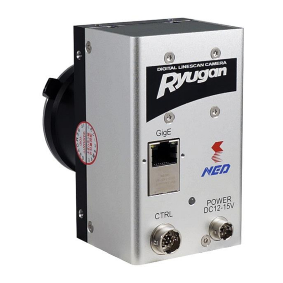
3.2 Input / Output Connectors and Indicator The layout of input /output connectors and the indicator lamp are as follows. Figure 3-2-1 Input/Output Connectors and Indicator UME-0111-01 RCDL4K8GE... -
Page 24: Power Supply Connection
3.3 Power Supply Connection 6 pin round shape push-pull lock type connector for Power supply. The pin assignment of the power supply connector is shown below. Figure 3-3-1 Power Supply Connector (HR10G-7R-6PB) Table 3-3-1 Pin Assignment of Power Supply Connection NAME Color of Cable NAME... -
Page 25: External Trigger Connector(Hr10G-10R-12Pb
3.4 External Trigger Connector(HR10G-10R-12PB) ◆ Round shape push-pull lock type. ◆ The pin assignment of the connector is shown below. External Trigger Figure 3-4-1 External Trigger Connector(HR10G-10R-12PB) This is used in External Trigger mode, or External Frame Trigger mode. Table 3-4-1 External Trigger Connector Pin Assignments NAME NAME LineIn1-... -
Page 26: Rs-422 Input
3.4.1 RS-422 Input When using RS-422 for input, connect a differential input via twisted pair as shown in figure 3-4-2. For correct operation, make sure to connect GND. With RS-422, multiple receivers can be connected to one driver. In such a case, only terminate the furthest receiver. On this camera, setting the Terminate setting to ON activates the terminator. -
Page 27: Ttl Input
3.4.3 TTL Input To use TTL input, connect the camera as in figure 3-4-3 below. To avoid damaging the device, do not input a signal to the – pin. In addition, make sure that the Terminate setting is OFF and the terminator is inactive. If the terminator is active, the signal may not be received correctly. -
Page 28: Lvds Output
3.4.5 LVDS Output If the receiver requires LVDS input, it can be connected by attaching resistors to the camera outputs. Multidrop is not supported. Connect only 1 receiver per camera. In addition, be sure to check that the receiver side must be terminated. If not, correct signals may not be received. -
Page 29: Relation Of External Trigger Input And Output
3.4.7 Relation of External Trigger Input and Output The external trigger output uses the external trigger input driver as an intermediary as shown in figure 3-4-7. Therefore it is possible to switch the output ON/OFF by use of an enable resistor. For settings, see “4.2.6.4 Setting Line Source”. Figure 3-4-7 Relation of External Trigger Input and Output UME-0111-01 RCDL4K8GE... -
Page 30: Connector
3.5 RJ-45 Connector The camera uses an RJ-45 connector complying with the Gigabit Ethernet standard (1000BASE-T). It can be connected to the LAN connector of your PC via a LAN cable (CAT-5e or above). For applications where there is a lot of vibration or movement, a screw-lock cable can be used. -
Page 31: Camera Control
4 Camera Control The camera supports the industrial camera control API Gen<I>Cam, and so camera settings can be easily changed from your application. The camera control registers are listed below. For instructions on how to change the settings, see the manual for your viewer software. - Page 32 X Offset Pixel No. 0~4088 OffsetX Number of pixels in a line. <0> Must be a multiple of 4. Sum / Average Addition/ Addition Average Binning Horizontal Mode <Sum> 1 / 2 1(OFF) / 2 pixels Binning Horizontal <1> Sum / Average Addition / Addition Average Binning Vertical Mode <Sum>...
- Page 33 Rising Edge : Rising Edge Rising Edge/ Falling Edge : Falling Edge Falling Edge/ Any Edge : Rising & Falling Edge Any Edge/ TriggerActivation Level High : “H” level activation Level High/ Level Low : “L” level activation Level Low <...
- Page 34 Color Transformation Control True : On True / Color Transformation False : Off False Enable <False> Gain 00 / Gain 01 / Gain 02 / Gain 10 / Gain 11 / Selects the Gain factor or Offset of the Color Transformation Gain 12 / Transformation matrix to access in the Value Selector...
- Page 35 (with terminal resistance) LVDS : LVDS Output /LVDS <TTL> 0 ~ 100000 0 ~ 100000 μsec. NED_LineMaskTimeR <0> 0 ~ 100000 0 ~ 100000 μsec. NED_LineMaskTimeF <0> Encoder Control Encoder Selector Encorder1 No need of Setting change Off / LineIn1 / Encoder Source A Encoder signal (A-phase) LineIn2 / LineIn3...
- Page 36 LineIn2 / LineIn3 <Off> Rising Edge / Falling Edge / Encoder Reset Any Edge / Selects the Activation mode of the Activation Level High / Encoder Reset Source signal. Level Low < Rising Edge > Software reset of encoder Encoder Reset (Independent of ncoderResetSource)...
- Page 37 Controls the delay (in GEV timestamp 0 ~ 4294967295 Gev SCPD counter unit) to insert between each <50> packet for this stream channel. NED additional features Disable / Correction OFF / Factory white / Factory black correction+ Factory white correction /...
-
Page 38: Details On Register System
(for Line selector) 7. Encoder Control (for Encoder) 8. User Set Control (for Memory Loading and saving) 9. Transport Layer Control (for GIG-E IF) 10. NED additional features (for Pixel Correction) 11.NED factory only (No use) Figure 4-2-1 Features RCDL4K8GE UME-0111-01... -
Page 39: Device Control
4.2.2 Device Control 4.2.2.1 Displaying Temperature of Camera Displays the temperature of camera inside. ・Register name Device Temperature ・Displaying Value (℃) Figure 4-2-2-1 Device Temperature UME-0111-01 RCDL4K8GE... -
Page 40: Image Format Control
4.2.3 Image Format Control 4.2.3.1 OffsetX and Width Settings By using the 2 settings OffsetX and Width, a specific region only can be read out from the camera. The range of values is as follows: ・OffsetX : 0 ~ 4088 ・Width : 8 ~ 4096 Figure 4-2-3-1-1 Offset X Figure 4-2-3-1-2 Width... -
Page 41: Height Setting
Width = b Output Pixel … OffsetX = a Sensor Pixel … … a+b-1 a+b+1 a+b+2 … 4093 4094 4095 4096 Figure 4-2-3-1-3 Valid Pixel Region 4.2.3.2 Height Setting The Height parameter is used to set the number of lines in 1 frame. The range of values is as follows: ・Height:16~4096 Figure 4-2-3-2-1 Height... -
Page 42: Setting Pixel Horizontal Binning Mode
Depending on the scan period and the height setting, it is possible that your application may time out. In such a case, either change the above settings or the timeout period in your application. 4.2.3.3 Setting Pixel Horizontal Binning Mode Sets the horizontal pixel binning mode for the camera output signal. -
Page 43: Setting Vertical Pixel Binning
Figure 4-2-3-5 Binning Vertical Mode 4.2.3.6 Setting Vertical Pixel Binning Sets the number of Vertical pixel binning of the output signal of the camera. ・Register name Binning Vertical ・VAL Vertical pixel binning 1(1 pixel, OFF of ) / 2(2 pixels) (Example) Binning Horizontal : 1(OFF) Figure 4-2-3-6 Binning Vertical... -
Page 44: Test Pattern
Figure 4-2-3-8 Pixel Format 4.2.3.9 Test Pattern The test pattern function allows you to check that data is being transferred correctly from the camera. ・Register name Test Pattern ・VAL Off / Grey Horizontal Ramp / NED_Grey Diagonal Ramp / Color Bar Figure 4-2-3-9-1 Test Pattern When GreyHorizontalRamp is selected, the below pattern is output. - Page 45 Figure 4-2-3-9-3 GreyHorizontalRamp It increases in increments of 1DN to 255DN in order from the first pixel 0DN. This pattern is repeatedly output. When NED_GreyDiagonalRamp is selected, the below pattern is output. Figure 4-2-3-9-4 NED_GreyDiagonalRamp Figure 4-2-3-9-5 NED_GreyDiagonalRamp The value increases by 1DN each pixel, up to 255DN from 0DN in both X-direction (horizontal direction) and Y-direction (vertical direction) in 8-bit mode, the pattern repeats.
- Page 46 Figure 4-2-3-9-6 ColorBar Figure 4-2-3-9-7 ColorBar 512 pixels in order from the first pixel,Black R:0,G:0,B:0 → White R:255,G:255,B:255 → Yellow R:255,G:255,B:0 → Light blue R:0,G:255,B: 255 → Green R:0,G:255,B:0 → Pink R:255,G:0,B:255 → Red R:255,G:0,B:0 → Blue R:0,G:0, B:255 RCDL4K8GE UME-0111-01...
-
Page 47: Acquisition Control
4.2.4 Acquisition Control 4.2.4.1 Setting Line Rate Sets the Line Rate. ・Register name Acquisition Line Rate ・VAL 300.000 ~ 30030.000 (*1) (Hz) (Example) (When 2640Hz is set as the line rate) Acquisition Line Rate : 2640 Figure 4-2-4-1 Acquisition Line Rate (*1) The maximum acquisition line rate at the time of the use of 4K pixels becomes 8kHz(RGB8Packed) (but, it may become lower than 8kHz depending on the processing time of (*2) The reciprocal of the line rate (1/Acquisition Line Rate)is set in increments of 0.100 μ... -
Page 48: Setting Trigger Selector
4.2.4.2 Setting Trigger Selector Sets the Trigger. ・Register name Trigger Selector ・VAL Frame Active, Exposure Start or DummyFrameOutput (Example) Trigger Selector : Exposure Start Figure 4-2-4-2 Trigger Selector 4.2.4.3 Setting Permission for using External Trigger Sets the “Trigger Mode” of Register name to get permission for using the External trigger. -
Page 49: Setting Trigger Signal
4.2.4.4 Setting Trigger signal Sets the “Trigger Source” of Register name when the “Trigger Mode” is set to “On” (Enable). ・Register name Trigger Source ・VAL NoConnect ( No connection Software ( Software Torigger Encoder 1 ( Encoder selection LineIn1 ( External trigger LineIn2 ( External trigger... -
Page 50: Setting Exposure Time
4.2.4.6 Setting Exposure Time Sets the value of the exposure time. The setting is enable; when “Off” on the “Trigger Mode” is set, or when “On” on the “Triger Mode” and “Timed” on the “Exposure Mode” are set. ・Register name Exposure Time ・VAL 2.000~3331.000 (0.1100 μ... -
Page 51: Analog Control
4.2.5 Analog Control 4.2.5.1 Setting Analog gain The camera can adjust the analog gain (x1 to x10 in 8 steps). ・Register name NED_AnalogGain ・VAL X 1.00 ~ X 10.00 (Example) Analog Gain : × 1.00 (Setting analog gain (x1.00)) Figure 4-2-5-1 NED_AnalogGain 4.2.5.2 Gain type selection Select a color to set the digital gain of the camera. -
Page 52: Setting Digital Gain
4.2.5.3 Setting Digital gain The camera can adjust the digital gain(x1 to x2 in 512 steps). ・Register name Gain ・VAL 1.000~2.000(0.001957step) (Example) Gain : 1.327 Figure 4-2-5-3 Gain 4.2.5.4 Offset type selection Select a color to set the offset of the camera. ・Register name Black Level Selector ・VAL... -
Page 53: Setting Digital Offset
4.2.5.5 Setting Digital Offset The offset can be adjusted. It is possible to set it in the adjustable range of–40~40(DN). ・Register name Black Level ・VAL -80 ~ 80(1.000000 step) (Example) BlackLevel : 10 Figure 4-2-5-5 Black Level 4.2.5.6 Setting Balance White Auto Sets the Balance White Auto ・Register name... -
Page 54: Color Transformation Control
4.2.6 Color Transformation Control 4.2.6.1 Color Transformation settings Set whether Color Transformation is enabled or disabled. Color Transformation is a function that converts an RGB value into another RGB value using the following formula. R’ Gain00 Gain01 Gain02 R Offset0 G’... - Page 55 Figure 4-2-6-2 Color Transformation Value Selector UME-0111-01 RCDL4K8GE...
-
Page 56: Setting Color Transformation Value
4.2.6.3 Setting Color Transformation Value Set the Color Transformation Value. Enter values for Gain 00 to Gain 22 and Offset 0 to Offset 2. ・Register name Color Transformation Value ・VAL Gain **:-3.0 ~ +3.0 Offset *:-512 ~ +512 (Example) Color Transformation Value 1.000 Figure 4-2-6-3 Color Transformation Value 4.2.7 Digital IO Control... -
Page 57: Setting Input Signal Polarity Reversal
Figure 4-2-7-2 Line Mode 4.2.7.3 Setting Input Signal Polarity Reversal Sets Input signal polarity reversal. ・Register name Line Inverter ・VAL False(Uncheck the box) Input signal polarity reversal (Disabling True(Check the box) Input signal polarity reversal (Enabling Input signal polarity reversal (Example) (Enabling Line Inverter : On... -
Page 58: Setting I/O Signal Format
Figure 4-2-7-4 Line Source 4.2.7.5 Setting I/O Signal Format Sets I/O signal format. ・Register name Line Format ・VAL TTL / RS422NotTerminate / RS422Terminate / LVDS (Example) Line Format : TTL Figure 4-2-7-5 Line Format *See Section 3.4.1 to 3.4.7 for Input and Output of RS422、LVDS and TTL. RCDL4K8GE UME-0111-01... -
Page 59: Setting External Line Trigger Chattering Prevention
4.2.7.6 Setting External Line Trigger Chattering Prevention This register enables the feature to prevent chattering or other unexpected variations in the signal. ・Register name NED_LineMaskTimeR NED_LineMaskTimeF ・VAL 0~1000000 (change invalid period):(μs) ① ② ③ ④ FrameTrigger MaskTimeR MaskTimeF MaskTimeF MaskTimeR Mask Frame with mask without mask... -
Page 60: Setting Input Signal For Encoder Source A
4.2.8.2 Setting Input Signal for Encoder Source A Sets Input signal for Encoder Source A. ・Register name Encoder Source A ・VAL off / LineIn1 / LineIn2 / LineIn3 (when “LineIn1” is set on “Encoder Source A”) (Example) Line Format : LineIn1 Figure 4-2-8-2 Encoder Source A 4.2.8.3 Setting Input Signal for Encoder Source B Sets Input signal for Encoder Source B. -
Page 61: Setting Encoder Divider
as the chattering signals by noise) High Resolution(Any changes by rising and falling edges on pulses of Phase A or Phase B are counted as one cycle of pulse of "High Resolution”. This may not work as noise filter for the chattering signals) (Example) Encoder Mode: Four Phase (when “Four Phase ”... -
Page 62: Setting Encoder Output Mode
4.2.8.6 Setting Encoder Output Mode Sets the Encoder Output Mode to output the pulse. ・Register name Encoder Output Mode ・VAL Off(Output no pulse) Position Up(Pulse output when new position in normal rotation direction is detected) Position Down(Pulse output the pulse when new position in reverse rotation direction is detected) Direction Up(Pulse output in normal rotation direction) Direction Down(Pulse output in reverse rotation direction) -
Page 63: Setting Encoder Reset Signal
(when “10μsec” is set on “Encoder Timeout”) (Example) Encoder Timeout : 10 Figure 4-2-8-8 Encoder Timeout 4.2.8.9 Setting Encoder Reset Signal Sets the Encoder Reset signal. ・Register name Encoder Reset Source ・VAL Off(No Reset Source) / Acquisition Start / Acquisition End / Frame Start / Frame End / Exposure Start / Exposure End / LineIn1 / LineIn2 / LineIn3 (when “Frame End”... -
Page 64: User Set Control
(Example) Encoder Activation : Rising Edge Figure 4-2-8-10 Encoder Activation 4.2.9 User Set Control 4.2.9.1 Setting Memory Selection Selects the location of camera setting data saved in the flash memory. ・Register name User Set Selector ・VAL Default / User Set 1(Factory setting / User setting) (Example) User Set Selector : User Set 1 Figure 4-2-9-1 User Set Selector... -
Page 65: Setting Memory Saving
Figure 4-2-9-2 User Set Load 4.2.9.3 Setting Memory Saving (Saving the camera setting data into the flash memory) The current camera setting data is saved in the flash memory. ・Register name User Set Save ・VAL Execute() (Example) User Set Selector : User Set 1(Selecting User setting) User Set Save : Execute()(Saving User setting data) Figure 4-2-9-3 User Set Save 4.2.9.4 Resetting Factory camera setting... -
Page 66: Transport Layer Control
the camera unless the step ③ below is not followed. ③Set the “Execute()” on “User Set Save “ User Set Save : Execute() The camera setting data at factory shipping can be used to operate the camera even after the power for camera is off. Figure 4-2-9-4-3 User Set Save 4.2.10 Transport Layer Control 4.2.10.1 Setting Persistent IP... -
Page 67: Packet Size
Figure 4-2-10-1 Gev Current IP Configuration Persistent IP When the box is checked, Persistent IP address, Persistent Subnet mask and Persistent Default gateway are effective. 4.2.10.2 Packet Size Packet size can be changed via the GevSCPSPacketSize camera register. ・Register name Gev SCPS Packet Size ・VAL 512 ~... -
Page 68: Packet Delay
4.2.10.3 Packet Delay Packet Delay can be set via the following register. ・Register name Gev SCPD ・VAL 0~4294967295 (Example) Gev SCPD : 50 Figure 4-2-10-3 Gev SCPD Notes: Packet Delay is set to 0 at the time of shipping; however it should be set to as large a value as possible to obtain stable image data. -
Page 69: Ned Additional Features
4.2.11 NED additional features 4.2.11.1 Setting Pixel Correction Sets the method of the pixel correction. ・Register name NED_FFCMode ・VAL Disable (Factory black correction) Factory white (Factory black and white correction) User white (Factory black and user white correction) User black + Factory white... -
Page 70: Saving White Pixel Correction Data
4.2.11.3 Saving White Pixel Correction Data Acquires current white pixel correction data and saves it in the flash memory. One set of correction data can be saved for each step of analog gain. ・Register name NED_PRNUCalibration ・VAL Execute() (Example) NED_PRNUCalibration : Execute() Figure 4-2-11-3 NED_PRNUCalibration 4.2.11.4 Saving Black Pixel Correction Data Acquires current black pixel correction data and saves it in the flash memory. -
Page 71: Setting Procedure Of External Trigger Settings (For Examples)
4.3 Setting Procedure of External Trigger Settings (for Examples) 4.3.1 One-phase Trigger setting (for Example) This is the setting procedure in the case that “LineIn3” as “Line Selector” and “TTL” as “Line Format” are used. ① Setting No-Permission before using External Trigger After selecting “Trigger Selector“in the categories of “Acquisition Control”, set as follows. -
Page 72: Two-Phase Trigger Setting (For Example)
Trigger Mode : On (See section 4.2.4.3) Remark: The above settings can be saved. (See section 4.2.8.3 “Setting Memory Saving”) 4.3.2 Two-phase Trigger setting (for Example) This is the setting procedure in the case that “LineIn1” and “LineIn2” as “Line Selector” and “HighResolution” as “Encoder Mode” are used. ①... -
Page 73: Software Trigger Setting (For Example)
⑤ Selecting Encoder Mode After selecting “Encoder Mode” in the category of “Encoder Control” set as follows. HighResolution (Example) HighResolution Encoder Mode: See section 4.2.7.4 ⑥ Selecting External Trigger Signal Type “External Trigger Signal Type” can be set below. After selecting “Trigger Selector“ in the category of “Acquisition Control”, set as follows (Example) Encoder 1 and Rising Edge Trigger Source : Encoder1... - Page 74 ④ Trigger signal input The trigger signal is entered when the TriggerSoftware in the Acquisition Control category is executed. Trigger Software : Execute() Remark: The above settings can be saved. (See section 4.2.8.3 “Setting Memory Saving”) RCDL4K8GE UME-0111-01...
-
Page 75: Calculating The Maximum Value Of Packet Delay
4.4 Calculating the Maximum Value of Packet Delay The maximum value for the packet delay setting can be calculated as below. In order to achieve the desired frame rate without dropping frames, it is necessary to set a value smaller than the maximum packet delay. Payload Size = Width x Height x (No. -
Page 76: Exposure Mode And Timing
4.5 Exposure Mode and Timing The camera has three exposure modes. 4.5.1 Free run Exposure Mode The free run exposure mode can be used when the “Trigger Mode” is “Off” (See section 4.2.4.3 but set “Off” at this time) (Disable). The Acquisition Line Rate and the Programmable Exposure Time are set in the camera control registers. -
Page 77: External Trigger (Timed) Exposure Mode
4.5.2 External Trigger (Timed) Exposure Mode The external trigger (Timed) exposure mode can be used when ”On” (Enable) on “Trigger Mode” and “Timed” on “Exposure Mode” are set. The line period is determined by the time from rising edge to rising edge of the trigger pulse cycle. -
Page 78: External Trigger (Triggerwidth) Exposure Mode
4.5.3 External Trigger (TriggerWidth) Exposure Mode The external trigger (Trigger Width) exposure mode can be used when ”On” (Enable) on “Trigger Mode” and “Trigger Width” on “Exposure Mode” are set. The line period is determined by the time from rising edge to rising edge of the trigger pulse cycle. -
Page 79: Setting Offset
4.6 Setting Offset In the diagram below, the horizontal axis indicates the volume of light and vertical axis indicates the output. Fs shows the output at saturation. Dd shows the output at darkness. (Both Fs and Dd are digital.) Se shows for the saturation current, or the amount of exposure when the output saturates. -
Page 80: Setting Gain
4.7 Setting Gain The camera can adjust the analog gain (x1 to X10.0 in 8 steps) and the digital gain. As the diagram below indicates, increasing the gain setting increases the slope of the camera’s response curve and results in a higher camera output for a given amount of light. - Page 81 Gain-Sensitivity is shown below. Table 4-7-1 Gain-Sensitivity Sensitivity Analog Amplifier (V/lx s) x1.00 0.0dB x2.00 6.0dB x3.00 9.5dB x4.00 12.0dB x5.00 14.0dB x6.00 15.6dB x8.00 18.1dB x10.00 20.0dB Digital gain x1, Pixel correction: default, (Factory white correction data, Correction level 800DN) UME-0111-01 RCDL4K8GE...
-
Page 82: Pixel Correction
4.8 Pixel Correction Generally speaking, image sensors (CCD, CMOS and so on) have fixed pattern noise and photo response non-uniformity. When you use the lens, lens shadings and light sources also can cause non-uniformity. The camera is set to the optimal correction before shipping in order to provide images of high grade. -
Page 83: Gamma Correction Setting
4.9 Gamma Correction Setting Switches Gamma correction value. The relation between Input and Output should be calculated to the following formula. Output = 1023* (Input / 1023) ^ (gamma) Figure 4-9-1 Gamma Correction Characteristics UME-0111-01 RCDL4K8GE... -
Page 84: Basic Camera Setting Checks
5 Basic Camera Setting Checks 5.1 Before Power On Check whether there are any dents or scratches on the camera. There might have been damage to the camera’s connectors or internals during transport. ①Check the pin assignments of the power cable(See figure 3-3-1 and table 3-3-1) ②Check that your network device supports 1000-Base T and Jumbo Frames. -
Page 85: Sensor Handling Instructions
6 Sensor Handling Instructions 6.1 Electrostatic Discharge and the Sensor The CMOS sensors are susceptible to damage from electrostatic discharge and can deteriorate as a result. Take care when handing the sensor. 6.2 Protecting Against Dust, Oil and Scratches The CMOS sensor window is part of the optical path and should be handled like other optical components with care. -
Page 86: Troubleshooting
7 Troubleshooting The following pages contain several troubleshooting charts that can help you find the cause of problems users sometimes encounter. 7.1 No Image The camera has the correct connections The indicator is glowing. with the power source. The power source meets the specified voltage. After power on, the power source meets the specified voltage. - Page 87 Is the LAN port set up correctly? Set up the LAN port correctly. The camera may be out of order. Please contact us for service. カメラの修理をご依頼ください。 The capture software program is Check whether the software included on custom made. the GigEGrab can capture images. With the GigEGrab sample software program The capture software must provided, no image is captured.
-
Page 88: Noise On Image
7.2 Noise on Image The camera has been used for 3 or Noise is present from more years, or the ambient the beginning. temperature is higher than room temperature. A servomotor or a magnetic valve is placed There are some consumable parts near the camera. -
Page 89: Camera Becomes Hot
The power source has no fluctuation in voltage and is not deteriorated. Use a stable power supply. When the camera gain is on a high level, bright spots occur without incident light. The camera may be out of order. Please Secondary radiation (rays) -
Page 90: Others
The contents of this document are subject to change without prior notice. ⚫ Every care has been taken in the preparation of this User’s Manual. If you should discover ⚫ any errors or omissions, please notify your nearest NED representative. 8.2 Contact for support Nippon Electro-Sensory Devices Corporation Head Office... - Page 91 Revision History Revision Number Date Changes 01 Oct 2020 Initial release UME-0111-01 RCDL4K8GE...
Need help?
Do you have a question about the GiGE VISION RCDL4K8GE and is the answer not in the manual?
Questions and answers