
Related Manuals for NED RMSL6K52CL


Summary of Contents for NED RMSL6K52CL
- Page 1 User’s Manual Line Scan Camera Model:RMSL6K52CL NIPPON ELECTRO-SENSORY DEVICES CORPORATION...
- Page 2 Directive on Waste Electrical and Electronic Equipment (WEEE) Please return all End of Life NED products to the distributor from whom the product was purchased for adequate recycling and / or disposal. All costs of returning the Product to NED are borne by the shipper.
- Page 3 Introduction Thank you for purchasing NED’s Line Scan Camera. We look forward to your continued custom in the future. For safety use ◆ For your protection, please read these safety instructions completely before operating the product and keep this manual for future reference.
- Page 4 Design the system configuration so that a loop will not be formed by the ground potential differential. ◆ Do not disconnect the camera while rewriting an embedded memory. ◆ When you change exposure mode that is set at NED factory, input control signal (CC1) from the capture board. RMSL6K52CL...
- Page 5 ◆ As a general rule, in the first instance fault diagnosis should take the form of a telephone call or an email to enable us to assess the circumstances of the malfunction. ◆ However, depending on the customer’s requests, we, or our agent, may require an additional fee for this service. RMSL6K52CL UME-0093-03...
- Page 6 On request, arrangements can be made separately. Scope of Repair Service The above assumes business dealings and usage to take place in the customer’s ◆ region / country. In cases of business dealings and/or usage outside the customer’s region/country, separate consultation is required. RMSL6K52CL UME-0093-03...
-
Page 7: Table Of Contents
4.2.2 Setting Digital Gain 4.2.3 Setting Digital Offset 4.2.4 Setting Exposure Mode 4.2.5 Setting Scan Rate 4.2.6 Setting Exposure Time 4.2.7 Setting Pixel Correction mode 4.2.8 Setting Pixel Correction Levei 4.2.9 Generating Test Pattern 4.2.10 Setting the Pixel Readout Direction RMSL6K52CL UME-0093-03... - Page 8 5 Sensor Handling Instructions 5.1 Electrostatic Discharge and the Sensor ------------------------------------------------------- 52 5.2 Protecting Against Dust, Oil and Scratches -------------------------------------------------- 52 5.3 Cleaning the Sensor Window ---------------------------------------------------------------------- 52 6 Troubleshooting 6.1 When there is no Image ----------------------------------------------------------------------------- 53 RMSL6K52CL UME-0093-03...
- Page 9 6.3 When the Camera becomes hot ------------------------------------------------------------------ 57 7 Others 7.1 Notice ----------------------------------------------------------------------------------------------------- 58 7.2 Contact for support ----------------------------------------------------------------------------------- 58 7.3 Product Support --------------------------------------------------------------------------------------- 59 7.3.1 Warranty card (attach a separate) 7.3.2 When you need to repair Revision History RMSL6K52CL UME-0093-03...
-
Page 10: Product Outline
⚫ Inspection of glass and sheet-like objects ⚫ Printed circuit board inspection ⚫ This camera utilizes an Intelligent Transportation System ⚫ Outdoor surveillance Wide dynamic range prevents the camera from saturation caused by direct rays and specular refection rays. RMSL6K52CL UME-0093-03... - Page 11 2. Resolution: 10μm 3. Inspection time: less than 30 seconds Unit Configuration 1. Camera: Line scan camera 2. Controller: Dedicated software for PC system 3. Size: L930 x D500 x H500 (mm) Applicable Fields Inspection of patterns on film PCBs RMSL6K52CL UME-0093-03...
-
Page 12: Image Sensor
The Performance Specifications are shown in Table 1-1. It shows the data when the camera is operating at maximum scan rate, unless otherwise specified. Table 1-4-1 Performance Specifications Specifications Items RMSL6K52CL Number of Pixels 6144 Pixel Size H x V (μm) 7x7 Sensor Length (mm) 43.008... - Page 13 3 Test Pattern Output On/Off Additional Function 4 Programmable Exposure Control 5 Scan Direction Switching 6 Selectable Data Rate 7 Display of Internal Temperature of Camera *1) DN : Digital Number (10-bit : 0 -1023) *2) Measurements were made at room temperature. RMSL6K52CL UME-0093-03...
- Page 14 The quantum efficiency is shown below. Figure 1-4-1 Quantum efficiency RMSL6K52CL UME-0093-03...
-
Page 15: Camera Setting And Optical Interface
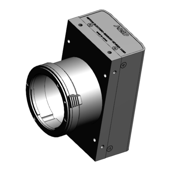
8mm, and less than 6mm for the side. ◆ No X-, Y-axis orientation and tilt adjustment mechanism is available. Please prepare an adjustment mechanism if required. RMSL6K52CL UME-0093-03... - Page 16 The dimensions of the camera are shown below. Nikon F mount Figure 2-2-1 Dimensions of the Camera RMSL6K52CL UME-0093-03...
-
Page 17: Optical Interface
CMOS image sensors are sensitive to infrared (IR). We recommend using daylight colour fluorescent lamps that have low IR emissions. If you use a halogen light source, to prevent infrared from distorting the images use an IR cutoff filter that does not transmit wavelengths. RMSL6K52CL UME-0093-03... -
Page 18: Hardware
Supply DC +12V 15W Figure 3-1-1 Connections between Camera and Frame Grabber Board and Power Supply There are two connectors available for the Camera Link Medium Configuration board. Always check the frame grabber board specifications before making connections. RMSL6K52CL UME-0093-03... -
Page 19: Input / Output Connectors And Indicator
SOL 6M CL E* (20~66MHz) SOL 6M FC E* (20~85MHz) 3.2 Input / Output Connectors and Indicator The layout of input /output connecters and the LED indicator are as follows. Figure 3-2-1 Input/Output Connectors and Indicator RMSL6K52CL UME-0093-03... -
Page 20: Connectors・Pin Assignments・Cables
100Ω LVDS_DRIVER(NS) LVDS_RECEIVER(NS DS90CR285MTD Channel Link Bus equivalent DS90CR286MTD LVAL,FVAL recommended DVAL,SP PortG~H Z0± Z0± 100Ω Z1± Z1± 100Ω Z2± Z2± 100Ω Z3± Z3± 100Ω CK ZClk± ZClk± 100Ω Figure 3-3-1 Camera / Frame Grabber Interface(Base, Medium) RMSL6K52CL UME-0093-03... - Page 21 The camera has 26-pin MDR connectors for control signals of Camera Link, data signals and serial communications. The camera also has a 4-pin HIROSE connector for power supply. Figure 3-3-3 Camera Link Connector ⚫ Half pitch (miniature half ribbon) shape ⚫ Locking screw (UNC #4-40) type RMSL6K52CL UME-0093-03...
- Page 22 3M: 14B26 – SZLB – xxx - 0LC by or equivalent ◆ To avoid uncoupling of the cable connectors during power on, make sure to clamp them with the locking screws. ◆ Do not unplug the cables while power is being supplied to the camera. RMSL6K52CL UME-0093-03...
- Page 23 Figure 3-3-4 Power Supply Connector (HIROSE: HR10G-7R-6PB) Table 3-3-2 Pin Assignment of Power Supply Connector NAME Colour of Cable DC12 –15V White DC12 –15V DC12 –15V - Green Black - Note: The cable colour in the table describes the compatible cable DGPSH-10. RMSL6K52CL UME-0093-03...
-
Page 24: Power Supply
If the lamp fails to illuminate even after power is switched on, turn off power immediately. Inspect wiring. Check the voltage and capacity of the supplied power source. It is recommended that the shield processing of the power cable to be connected with GND on the power supply side. RMSL6K52CL UME-0093-03... -
Page 25: Camera Control
VAL CR □ □ ⚫ Format CMD: Control text (3 Bytes) Use 3 lowercase letters only. No numerals allowed. Carriage Return (0x0D) □ Space (0x20) or Comma (0x2C) VAL: Setting value (decimal, maximum 5 digits) <Example> gax 0 CR RMSL6K52CL UME-0093-03... -
Page 26: Camera Sending Message (Pc Receiving Message)
>OK CR >gax 0 CR EOT Table 4-1-3-1 Error Messages Camera Response Meaning Camera executed command CMD ERR! Command is not valid CMD OVR ERR! Command text line is too long VAL ERR! Parameter accepted was outside of specified MEM ERR! Memory error RMSL6K52CL UME-0093-03... -
Page 27: Camera Control Commands
CameraLink Output 85/60/4 85:85MHz 60:60MHz clkcl Clock 40:40MHz 0:GenICam_2X2E Output Tap Format tapg 1:GenICam_1X2 γ=Val / 1000 Gamma Correction 250 to gamma Example : If Val=450, 1000 Setting 4000 γ=450 / 1000=0.45 Memory Initializing Reset to factory settings RMSL6K52CL UME-0093-03... - Page 28 Obtain any white correction data correction data and save it in memory Returns the current camera Operation Status Readout settings. The internal temperature of the Camera temperature temp camera is displayed.[℃] Communication speed 9600/ 9600(at factory setting/ sbaud 9600 selection 115200 115200bps RMSL6K52CL UME-0093-03...
-
Page 29: Details On Commands
255 CR (Setting digital gain 255(1023/(1023-255)=x1.33)) >OK >gdx 255 4.2.3 Setting Digital Offset Sets digital offset -127 to +127(8-bit:0.5DN/Step 10-bit:2DN/Step) □ ⚫ Format VAL CR ⚫ ⚫ -127 to 127 <Example> □ 10 CR (8/10bit Setting digital offset +5/+20DN(8-bit/10-bit)) >OK >odx 10 RMSL6K52CL UME-0093-03... -
Page 30: Setting Exposure Mode
The relation between the scan period and the exposure time is as follows. Scan period (reciprocal number of the scan rate) > Exposure time + blanking (fixation time) Setting the scan rate ● The camera coordinates the exposure time automatically if the inequality RMSL6K52CL UME-0093-03... -
Page 31: Setting Pixel Correction Mode
CR (for factory black correction + factory white correction , Correction level 900) >OK >shc 1,900 4.2.8 Setting Pixel Correction Levei Sets pixel correction.level ⚫ Format CMD□VAL□ CR ⚫ ffct ⚫ 0 to 1023 (Setting correction level:10-bit) <Example> ffct□900 CR (Correction level 900) >OK >ffct 900 RMSL6K52CL UME-0093-03... -
Page 32: Generating Test Pattern
CR (Reverse) >OK >rev 1 4.2.11 Setting Data Format Sets the data format of output signals. □ ⚫ Format VAL CR ⚫ ⚫ 0,1 (0: 8-bit / 1: 10-bit) <Example> □ 0 CR (8-bit output) >OK >pfm 0 RMSL6K52CL UME-0093-03... -
Page 33: Setting Output Data Clock
CR (GenICam_4x2E) >OK >tapg 0 4.2.14 Setting Gamma correction Switch the gamma correction settings. ⚫ ・Format CMD□VAL CR ⚫ ・CMD gamma ⚫ ・VAL 250~4000(γ=VAL/1000 it is effective) <Example> gamma□450 CR (0.45 at gamma correction setting) >OK >gamma 450 RMSL6K52CL UME-0093-03... -
Page 34: Memory Initializing (Initializing Camera Settings)
<Example> rst CR >OK >Type=RMSL8K76CL >Ver.=1.13_0x0253 >Serial=3 >gax 0 >gdx 0 >odx 0 >inm 0 >prd 8183 >expo 120000 >ffcm 1 >ffct 800 >tpn 0 >rev 0 >pxf 0 >clkcl 85 >tapg 0 >gamma 1000 >logmode 1 >rst RMSL6K52CL UME-0093-03... -
Page 35: Memory Load
>ffct 800 >tpn 0 >rev 0 >pxf 0 >clkcl 85 >tapg 0 >gamma 1000 >logmode 1 >rfd 4.2.17 Memory Save Stores the current camera settings in the flash memory. ⚫ Format CMD CR ⚫ <Example> sav CR >OK >sav RMSL6K52CL UME-0093-03... -
Page 36: Capture Black Pixel Correction Data
4.2.19 Capture white pixel correction data Save the user arbitrary white pixel correction data of analog gain in flash memory. The data at each step of analog gain can be saved.. ⚫ Format CMD CR ⚫ <Example> wht CR >OK > wht RMSL6K52CL UME-0093-03... -
Page 37: Returning The Cameras Settings To The Its Original Status
>tpn 0 >rev 0 >pxf 0 >clkcl 85 >tapg 0 >gamma 1000 >logmode 1 >sta 4.2.21 Displaying the internal temperature of Camera Displays the temperature in the Camera. ⚫ Format CMD CR ⚫ temp <Example> temp >OK >Temp=37.2 >temp RMSL6K52CL UME-0093-03... -
Page 38: Selecting The Communication Speed
4.2.22 Selecting the communication speed Selects the baud rate 9600bps or 115200bps to set the speed of communication with PC. ⚫ Format CMD VAL CR ⚫ sbaud <Example> sbaud 115200 >OK >sbaud 115200 RMSL6K52CL UME-0093-03... -
Page 39: Digital Processing Flow In Fpga
(2) Reads out the latest camera settings from the flash memory. (User settings if any or factory default settings) (3) Set up the camera with the setting value from the flash memory. After those sequences, the camera is ready to get images and output data. RMSL6K52CL UME-0093-03... -
Page 40: Saving And Loading Camera Settings
(from frame grabber board) Free Run (Programmable time setting) (Factory Setting) Not in use Ext Edge (External trigger edge + Programmable time setting ) External trigger (CC1) is required Ext Level (External trigger level time setting) External trigger (CC1) is required RMSL6K52CL UME-0093-03... -
Page 41: Serial Communication Settings
The camera outputs 8-bit digital data through 8 taps. 8bit 10bit bit9 bit9 bit8 bit8 bit7 bit7 bit6 bit6 bit5 bit5 8bit 10bit bit4 bit4 bit3 bit3 bit2 bit2 bit1 bit1 bit0 bit0 Figure 4-7-1 Pin Assignments of Digital Data RMSL6K52CL UME-0093-03... - Page 42 Invalid Invalid Invalid 6141 6143 Invalid Invalid Invalid Invalid (#1TAP VIDEO Invalid Invalid Invalid Invalid 6142 6144 Invalid Invalid Invalid Invalid (#2 TAP ◆ FVAL = 0 (low level) fixed Figure 4-7-2b Video Output Phase of the Camera RMSL6K52CL UME-0093-03...
-
Page 43: Exposure Mode And Timing Chart
GenICam_1X2 36.14 51.20 76.80 (unit:μs) Notes: *The exposure time is increased by an increments of 200ns *Scan rate (1/scan) > Exposure time scan Exposure ① ② ③ ④ ⑤ ⑥ Readout (LVAL) Figure 4-8-1-1 Free Run Exposure Mode RMSL6K52CL UME-0093-03... -
Page 44: External Trigger Exposure Mode (Trigger Edge)
GenICam_1X2 (μs) * *The exposure time is increased by an increments of 200ns (unit:μs) ① ② ③ ④ ⑤ ⑥ Trigger (CC1) ① ② ③ ④ ⑤ Exposure Readout (LVAL) Figure 4-8-2-1 External Trigger (Trigger Edge) Exposure Mode RMSL6K52CL UME-0093-03... -
Page 45: External Trigger Exposure Mode (Trigger Level)
GenICam_2X2E ≒14 GenICam_1X2 LVAL Rising edge (μs) Table 4-8-3-1 Programmable Exposure Time (unit:μs) ① ② ③ ④ ⑤ ⑥ Trigger (CC1) ② ③ ⑥ ① ④ ⑤ Exposure Readout (LVAL) Figure 4-8-3-1 External Trigger (Trigger Level) Exposure Mode RMSL6K52CL UME-0093-03... -
Page 46: Setting Offset
By setting the offset, you can set the Y-intercept arbitrarily. DF shows the digital offset value. The gradients of lines do not change. DF : Offset Value Output Volume of Light (lx・s) Figure 4-9-2 Offset Adjustment ◆ Adjust gain and offset to meet your system’s requirements. RMSL6K52CL UME-0093-03... -
Page 47: Setting Gain
Gain a Gain b Gain c Amount of Incident Light (lxs) Figure 4-10-1 PGA Gain Adjustment ◆ Gain and noise values are proportionally related. ◆ Adjust amount of gain in accordance with the requirements of your camera system. RMSL6K52CL UME-0093-03... - Page 48 Table 4-10-1 Gain-Sensitivity Sensitivity Analog Amplifier (V/lx s) x1.00 0.0dB x2.00 6.0dB x3.00 9.5dB x4.00 12.0dB x5.00 14.0dB x6.00 15.6dB x8.00 18.1dB x10.00 20.0dB 1000 Digital gain x1, Pixel correction: default, (Factory white correction data, Correction level 800DN) RMSL6K52CL UME-0093-03...
-
Page 49: Pixel Correction
Vin :Input data (digital) Vout :Output data (digital) The corrected data is expressed in the following equation. Vout=(Vin-Cal_bl)xTarget_val/(Cal_wh-Cal_bl) Waveform before bit correction Output Pixel Number Waveform after bit correction Output Pixel Number Figure 4-11-1 Waveform before and after bit correction RMSL6K52CL UME-0093-03... -
Page 50: Command Settings
(3) Confirm that the camera returns “>OK” and “>wht”. Thus user white correction data is saved and loaded to the camera. (4) Send the “ffcm 2 VAL CR” command through serial communication. Then the user white correction will be on and set the correction level as “VAL”. RMSL6K52CL UME-0093-03... -
Page 51: Test Pattern
The test pattern is a ramp from 0 to 255DN in 8-bit mode, and then it repeats itself from 0 again 24times. The test pattern is a ramp from 0 to 1023DN, 0 to 511 in 10-bit mode, and then it repeats itself from 0 again 4 times. RMSL6K52CL UME-0093-03... -
Page 52: Sensor Handling Instructions
Dust can obscure pixels, producing dark lines on the image. 5.3 Cleaning the Sensor Window Dust: Can usually be removed by blowing the window surface using a compressed air blower. Oil: Wipe the window with a lint-free cloth wiper moistened with ethyl alcohol carefully and slowly. RMSL6K52CL UME-0093-03... -
Page 53: Troubleshooting
The sample software program is used to with the camera control the camera and is communicating successfully. with the camera successfully. To next page To next page To next page Confirm the communication software, the control protocol for the camera and commands. RMSL6K52CL UME-0093-03... - Page 54 The optical axes of the camera and Check the light source. If the the image sensor are aligned. images are too dark, try to increase the light intensity, and vice versa. The camera could be faulty. Please contact us for assistance. カメラの修理をご依頼ください。 RMSL6K52CL UME-0093-03...
-
Page 55: When Noise Is Present In The Image
(attached to a machine which applies stress to the cables). Check the condition of the camera cables and the power supply cable. The camera could be faulty. Please contact us for assistance. To next page RMSL6K52CL UME-0093-03... - Page 56 When the camera gain is on a high level, bright spots occur without incident light. The camera could be faulty. Please Secondary radiation (rays) contact us for assistance. could cause bright spots, but カメラの修理をご依頼ください。 this is not malfunction. RMSL6K52CL UME-0093-03...
-
Page 57: When The Camera Becomes Hot
Allow sufficient air circulation around the camera to give it the longer life. より長くお使いいただくために、さらに、通気 性を高めることが効果的です Keep the ambient temperature within the range of the specifications. The camera could be faulty. Please contact us for assistance. カメラの修理をご依頼ください。 RMSL6K52CL UME-0093-03... -
Page 58: Others
⚫ Contents of this document are subject to change without prior notice. ⚫ Every care has been taken in the preparation of this User’s Manual. If you should discover any errors or omissions, please notify your nearest NED representative. 7.2 Contact for support... -
Page 59: Product Support
If there is still a problem with your camera after checking it in accordance with the troubleshooting guide, turn off the power and call your NED representative. In such case, please inform us of the status of the camera. You can get the status by executing the “sta”... -
Page 60: Revision History
Revision History Revision Date Changes Number Jul 25, 2018 Initial release Jan. 29, 2021 Table 1-4-1:Error correction Oct. 07, 2021 complete revision RMSL6K52CL UME-0093-03...
Need help?
Do you have a question about the RMSL6K52CL and is the answer not in the manual?
Questions and answers