
Related Manuals for NED RMSL6K17GE


Summary of Contents for NED RMSL6K17GE
- Page 1 User’s Manual Line Scan Camera Type:RMSL6K17GE NIPPON ELECTRO-SENSORY DEVICES CORPORATION GigE Vision is a registered trademark of AIA...
- Page 2 EN61000-6-2:2005 Directive on Waste Electrical and Electronic Equipment (WEEE) Please return all End of Life NED products to the distributor from whom the product was purchased for adequate recycling and / or disposal. All costs of returning the Product to NED are borne by the shipper.
- Page 3 Introduction Thank you for purchasing NED’s Line Scan Camera. We look forward to your continued custom in the future. For safety use For your protection, please read these safety instructions completely before operating the product and keep this manual for future reference.
- Page 4 Do not disconnect the camera while rewriting the embedded memory. When you change the exposure mode that is set at the NED factory, input control signal (CC1) from the capture board. SG (Signal Ground) and FG (Frame Ground) are connected inside the camera.
- Page 5 As a general rule, in the first instance fault diagnosis should take the form of a telephone call or an email to enable us to assess the circumstances of the malfunction. However, depending on the customer’s requests, we, or our agent, may require an additional fee for this service. U M-0099-03 RMSL6K17GE...
- Page 6 On request, arrangements can be made separately. Scope of Repair Service The above assumes business dealings and usage to take place in the customer’s region / country. In cases of business dealings and/or usage outside the customer’s region/country, separate consultation is required. RMSL6K17GE UM-0099-03...
-
Page 7: Table Of Contents
4.1.2 List of Camera Control Registers ................. 27 4.2 Details on register system ....................32 4.2.1 Category ........................32 4.2.2 Device Control ......................33 4.2.2.1 Displaying Temperature of Camera ..............33 4.2.3 Image Format Control ....................34 4.2.3.1 OffsetX and Width Settings ................34 U M-0099-03 RMSL6K17GE... - Page 8 4.2.7.10 Setting Encoder Reset Activation ..............51 4.2.8 User Set Control ......................52 4.2.8.1 Setting Memory Selection .................. 52 4.2.8.2 Setting Memory Loading ..................52 4.2.8.3 Setting Memory Saving ..................53 4.2.8.4 Resetting Factory camera setting ..............53 4.2.9 Transport Layer Control ....................54 RMSL6K17GE UM-0099-03...
- Page 9 7.1 No Image ..........................74 7.2 Noise on Image ........................76 7.3 Camera becomes hot ......................77 8 Others ..................78 8.1 Notice ............................78 8.2 Contact for support ....................... 78 8.3 Product Support ........................79 Revision History ..............80 U M-0099-03 RMSL6K17GE...
-
Page 10: Product Outline
Flat panel display inspection Inspection of glass and sheet-like objects Printed circuit board inspection This camera utilizes an Intelligent Transportation System Outdoor surveillance An example of visual inspection of metallic parts is shown below . RMSL6K17GE UM-0099-03... - Page 11 Metallic parts with cylindrical/conical shapes (surface and roller end faces) ・Automobile component ・Architectural reinforcement parts ・Various pin parts Typical detection item ・Chip ・Dent ・Scratch ・Chipped end faces ・External dimensions Device specification 1. Camera: 8192 pixel Line scan camera 2. Controller: Dedicated software for PC system U M-0099-03 RMSL6K17GE...
-
Page 12: Performance Specifications
The Performance Specifications are shown below. The data is shown when the camera is operating at the maximum scan rate, unless otherwise specified. Table 1-3-1 Performance Specifications Specifications Items RMSL6K17GE Number of Pixels 6144 Pixel Size H x V (μm) 7x7 Sensor Length (mm) 43.008... - Page 13 4.Scan Direction Switching 5.Test Pattern Output 6.Two-phase Trigger Remarks: 1)DN : Digital Number (8bit : 0 -255 / 10bit : 0 -1023) 2)Measurements were made at room temperature The spectral Responsivity is shown below. Figure 1-3-1 Spectral Responsivity U M-0099-03 RMSL6K17GE...
-
Page 14: Camera Setting And Optical Interface
If using the front panel M4 mounting holes, the screw length for fixing the camera should be less than 6mm. No X-, Y-axis orientation and tilt adjustment mechanism is available. Please provide an adjustment mechanism yourself as necessary. RMSL6K17GE UM-0099-03... - Page 15 The dimensions for camera are shown below. Figure 2-2-1 Dimensions (F Mount) U M-0099-03 RMSL6K17GE...
-
Page 16: Optical Interface
CMOS image sensors are sensitive to infrared (IR). We recommend using daylight color fluorescent lamps that have low IR emissions. If you use a halogen light source, to prevent infrared from distorting the images use an IR cutoff filter that does not transmit IR wavelengths. RMSL6K17GE UM-0099-03... -
Page 17: Hardware
Please choose equipment suitable for your application’s requirements. LAN Cable Cat-5e grade or higher Line scan camera Trigger controller Power Supply Cable Camera Power Supply DC+12V 15W Figure 3-1-1 Connections between Camera and PC etc. U M-0099-03 RMSL6K17GE... - Page 18 Gigabit (1port) Gigabit (1port) Example of connection between Example of connection between 1 PC and 3 cameras of 1 PC and 3 cameras Gigabit Gigabit Switching (1port) Gigabit (Multi port) Figure 3-1-2 Example of connection for 1 PC RMSL6K17GE UM-0099-03...
-
Page 19: Input / Output Connectors And Indicator
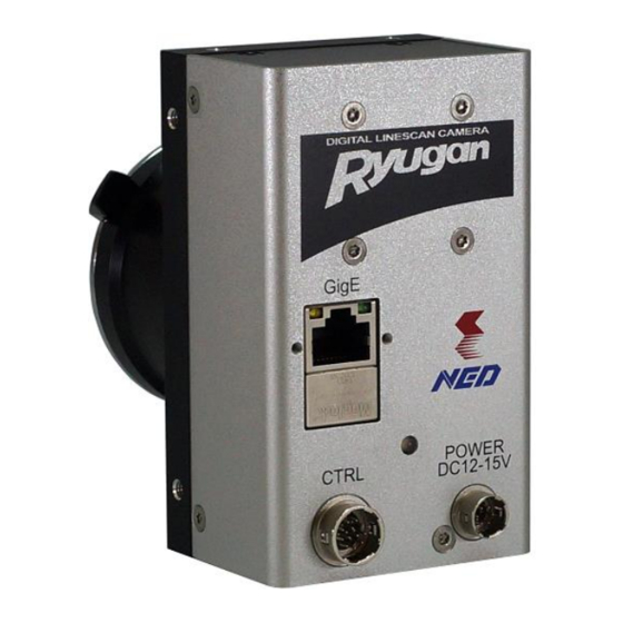
3.2 Input / Output Connectors and Indicator The layout of input /output connectors and the indicator lamp are as follows. Figure 3-2-1 Input/Output Connectors and Indicator U M-0099-03 RMSL6K17GE... -
Page 20: Power Supply Connection
Place the camera far away from the apparatus generating noise. Do not arrange the signal cables and the power supply cable for camera adjacently. RMSL6K17GE UM-0099-03... -
Page 21: External Trigger Connector(Hr10G-10R-12Pb
3) Use a twisted pair cable, such that + and – are paired. ● RS-422, LVDS and TTL are supported for input/output. ● Polarity reversal & chatter prevention functions can be used on the input. U M-0099-03 RMSL6K17GE... -
Page 22: Rs-422 Input
Notes: The LVDS Multidrop function is not supported. Only connect 1 device per driver. If you need to send the signal to multiple cameras, it is possible to use the camera’s external trigger output for a cascade connection. RMSL6K17GE UM-0099-03... -
Page 23: Ttl Input
Multiple receivers can be connected to 1 camera when using RS-422. In such a case, only terminate the furthest receiver. Notes: Do not terminate multiple receivers. The signal level will decrease and the signal will not be received correctly. Figure 3-4-4 External Trigger Output Connection Diagram (RS-422) U M-0099-03 RMSL6K17GE... -
Page 24: Lvds Output
To use TTL output, connect the camera output as shown in figure 3-4-6. The Lo level output is 0V, the Hi level output is 3.3V. To avoid damaging the device, do not connect the – pin. Figure 3-4-6 External Trigger Output Connection Diagram (TTL) RMSL6K17GE UM-0099-03... -
Page 25: Relation Of External Trigger Input And Output
The external trigger output uses the external trigger input driver as an intermediary as shown in figure 3-4-7. Therefore it is possible to switch the output ON/OFF by use of an enable resistor. For settings, see “4.2.6.4 Setting Line Source”. Figure 3-4-7 Relation of External Trigger Input and Output U M-0099-03 RMSL6K17GE... -
Page 26: Connector
Camera Power Supply is off off (LED indication) off (LED indication) Camera Booting Up (Power On) Lights orange Lights orange Disconnected cable Lights red Device Discovery Blinks orange Stand-by transmitting image packets Lights green Transmitting image packets Blinks green RMSL6K17GE UM-0099-03... -
Page 27: Camera Control
DeviceTemperature Mainboard No need of Setting change Selector DeviceTemperature DeviceTemperature (℃) Image Format Control Number of pixels in a line. 4~6144 Width <6144> Must be a multiple of 4. Height 16~4096 Number of lines in a frame. U M-0099-03 RMSL6K17GE... - Page 28 Any Edge/ Level High : “H” level activation Level High/ Level Low : “L” level activation Level Low Timed :Value of ExposureTime Timed / TriggerWidth TriggerWidth:”H” time of External ExposureMode <Timed> trigger 2.0~3331.0 ExposureTime 0.1μsec / step <120.0> RMSL6K17GE UM-0099-03...
- Page 29 <0> Encoder Control EncoderSelector Encorder1 No need of Setting change Off/ EncoderSourceA LineIn1/LineIn2 Encoder signal (A-phase) /LineIn3 Four Phase : Combination of Four Phase/ A & B phases EncoderMode High Resolution One cycle of 4-state (with filtering) U M-0099-03 RMSL6K17GE...
- Page 30 User Set Control Default : factory settings Default/ UserSetSelector UserSet1 : user settings 1 UserSet1 Reads settings from internal memory UserSetLoad when 1 is written Saves Current camera set values by UserSetSave UserSetSelector in the memory NED additional features RMSL6K17GE UM-0099-03...
- Page 31 Target value of correction level 1~1023 NED_PRNUTarget (10bit DN) <800> Acquiring the data of user arbitrary NED_PRNUCalibration white correction and saving it in the memory Acquiring the data of user arbitrary NED_FPNCalibration black correction and saving it in the memory U M-0099-03 RMSL6K17GE...
-
Page 32: Details On Register System
5. Digital IO Control (for Line selector) 6. Encoder Control (for Encoder) 7. User Set Control (for Memory Loading and saving) 8. Transport Layer Control (for GIG-E IF) 9. NED additional features (for Pixel Correction) 10.NED factory only (No use) RMSL6K17GE UM-0099-03... -
Page 33: Device Control
4.2.2 Device Control 4.2.2.1 Displaying Temperature of Camera Displays the temperature of camera inside. ・Register name Device Temperature ・Displaying Value (℃) U M-0099-03 RMSL6K17GE... -
Page 34: Image Format Control
(e.g.) To specify pixel 513~ pixel 1536, set OffsetX = 512、Width = 1024. Width = b Output Pixel … OffsetX = a Sensor Pixel … … a+b-1 a+b+1 a+b+2 … 6141 6142 6143 6144 Figure 4-2-3-1 Valid Pixel Region RMSL6K17GE UM-0099-03... -
Page 35: Height Setting
1 Frame period (us)=1 Line Scan Period (us) x Height Depending on the scan period and the height setting, it is possible that your application may time out. In such a case, either change the above settings or the timeout period in your application. U M-0099-03 RMSL6K17GE... -
Page 36: Scan Direction
Pixel Format Setting The Pixel Format parameter is used to select the video output format. Supported formats are as follows: ・Register name Pixel Format ・VAL Mono8 / Mono10 / Mono10Packed The pixel layout of each format is as below: RMSL6K17GE UM-0099-03... -
Page 37: Test Pattern
8-bit signal can be output as video data. 4.2.3.5 Test Pattern The test pattern function allows you to check that data is being transferred correctly from the camera. ・Register name Test Pattern ・VAL Off / GreyHorizontalRamp / NED_Grey Diagonal Ramp U M-0099-03 RMSL6K17GE... - Page 38 Figure 4-2-3-5-2 Test Image of 10bit 8192 Pixels(GreyHorizontalRamp) It increases in increments of 1DN to 1023DN in order from the first pixel 0DN. This pattern is repeatedly output. When NED_GreyDiagonalRamp is selected, the below pattern is output. Figure 4-2-3-5-3 Test Pattern of 10bit 8192 Pixels(NED_GreyDiagonalRamp) RMSL6K17GE UM-0099-03...
-
Page 39: Acquisition Control
17kHz(Mono8) (but, it may become lower than 17kHz depending on the processing time of PC) *2)The reciprocal of the line rate (1/Acquisition Line Rate)is set in increments of 0.100 μ s. When a value of (1/Acquisition Line Rate)is not divisible in 100ns, the real set value is U M-0099-03 RMSL6K17GE... -
Page 40: Setting Trigger Selector
Sets the “Trigger Mode” of Register name to get permission for using the External trigger. Select “On” on the “Trigger Mode” if the External trigger is used. ・Register name Trigger Mode ・VAL Off / On (Disable/Enable) (Example) Trigger Mode: On RMSL6K17GE UM-0099-03... -
Page 41: Setting Exposure Mode
Timed (The set value of the “Exposure Time” is used as the exposure time) ・VAL Trigger Width (The “H” time of “Trigger pulse” of the “External Start” is used as the exposure time) (Example) Exposure Mode : Timed U M-0099-03 RMSL6K17GE... -
Page 42: Setting Exposure Time
Acquisition Line Rate <= 1 / (Exposure Time + 2.3) μ s 4.2.5 Analog Control 4.2.5.1 Setting Analog gain The camera can adjust the analog gain (x1 to x10 in 8 steps). ・Register name NED_AnalogGain ・VAL X 1.00 ~ X 10.00 RMSL6K17GE UM-0099-03... -
Page 43: Setting Digital Gain
Se: Saturation Exposure(DN) Fs:Saturation Output(DN) Minus offset Df:Dark Current (DN) Volume of Light(lx・s) Figure 4-2-5-3-1 Offset Adjustment Note: 1) Adjust amount of offset in accordance with the requirements of your camera system. The gradients of lines do not change. U M-0099-03 RMSL6K17GE... -
Page 44: Digital Io Control
VAL ( LineIn/ LineOut ) and the corresponding pins. 4.2.6.2 Setting Line Mode The “Line Mode” can be set automatically when the“Line Selector” is set. When “LineIn” of “Line Selector” is set, “Input” appears. When “LineOut” of “Line Selector” is set, “Output” appears. RMSL6K17GE UM-0099-03... -
Page 45: Setting Input Signal Polarity Reversal
Line Inverter : On 4.2.6.4 Setting Line Source Sets Line Source. ・Register name Line Source ・VAL Off/Acquisition Active/Frame Active/Exposure Active/Encorder1/ LineIn1/LineIn2/LineIn3(input) LineOut1/LineOut2 (output) 4.2.6.5 Setting I/O Signal Format Sets I/O signal format. ・Register name Line Format ・VAL RS422NotTerminate RS422Terminate U M-0099-03 RMSL6K17GE... -
Page 46: Setting External Line Trigger Chattering Prevention
④If you set NED_LineMaskTimeF to too large a value, valid trigger changes may go undetected and unwanted frames will be generated, so set the value as small as possible. RMSL6K17GE UM-0099-03... -
Page 47: Encoder Control
4.2.7.2 Setting Input Signal for Encoder Source A Sets Input signal for Encoder Source A. ・Register name Encoder Source A ・VAL LineIn1 LineIn2 LineIn3 (when “LineIn1” is set on “Encoder Source A”) (Example) Line Format : LineIn1 U M-0099-03 RMSL6K17GE... -
Page 48: Setting Input Signal For Encoder Source B
4.2.7.3 Setting Input Signal for Encoder Source B Sets Input signal for Encoder Source B. ・Register name Encoder Source B ・VAL LineIn1 LineIn2 LineIn3 (when “LineIn2” is set on “Encoder Source B”) (Example) Line Format : LineIn2 RMSL6K17GE UM-0099-03... -
Page 49: Setting Encoder Mode
Encoder Mode: Four Phase (when “Four Phase ” is set on “Encoder Mode”) 4.2.7.5 Setting Encoder Divider Sets numbers of Encoder Divider for outputting the pulse when the encoder input of the specified number is acquired. ・Register name Encoder Divider ・VAL 1~200 U M-0099-03 RMSL6K17GE... -
Page 50: Setting Encoder Output Mode
Static(No operation in time of Encoder Timeout) 4.2.7.8 Setting Time of Encoder Timeout Sets the time of Encoder Timeout. The status becomes “Encoder Idle” if the Encoder counter does not change during this time. ・Register name Encoder Timeout ・VAL 0~60000000 RMSL6K17GE UM-0099-03... -
Page 51: Setting Encoder Reset Signal
Falling Edge(Reset by falling edge of Input signal) Any Edge (Reset by rising and falling edges of Input signal) Level High (Reset state during the period of “High” of Input signal) Level Low (Reset state during the period of “Low” of Input signal) U M-0099-03 RMSL6K17GE... -
Page 52: User Set Control
The camera setting data selected by “User Set Selector” is read from the flash memory and is used to operate the camera. ・Register name User Set Load ・VAL Execute() (Example) User Set Selector : User Set 1(Selecting User setting) User Set Load : Execute() (Loading User setting data) RMSL6K17GE UM-0099-03... -
Page 53: Setting Memory Saving
② until the power for camera is off. After the power is off and then on, the previous camera setting data is used to operate the camera unless the step ③ below is not followed. U M-0099-03 RMSL6K17GE... -
Page 54: Transport Layer Control
The camera setting data at factory shipping can be used to operate the camera even after the power for camera is off. 4.2.9 Transport Layer Control 4.2.9.1 Setting Persistent IP Sets IP by checking the box. ・Register name Gev Current IP Configuration Persistent IP ・VAL True/False RMSL6K17GE UM-0099-03... - Page 55 When the box is checked, Persistent IP address, Persistent Subnet mask and Persistent Default gateway are effective. U M-0099-03 RMSL6K17GE...
- Page 56 Therefore, by increasing the packet size, the number of packets to send can be reduced, reducing the overall data volume. Notes: Do not set the size larger than your network’s MTU (Maximum Transmission Unit). Doing so will result in image data not being able to be sent. RMSL6K17GE UM-0099-03...
- Page 57 However, if the value is too large, the frame rate will drop. See 4.4 “Calculating the maximum value of packet delay” to set the most suitable value. U M-0099-03 RMSL6K17GE...
-
Page 58: Setting Pixel Correction
4.2.10 NED additional features 4.2.10.1 Setting Pixel Correction Sets the method of the pixel correction. ・Register name NED_FFCMode ・VAL Disable (Factory black correction) Factory white (Factory black and white correction) User white (Factory black and user white correction) User black + Factory white... -
Page 59: Saving White Pixel Correction Data
However, dark and light details of the white object will be picked out, so the lens should be defocused. Setting condition of black pixel correction Put on a lens cap to darken the camera view. U M-0099-03 RMSL6K17GE... -
Page 60: Setting Procedure Of External Trigger Settings (For Examples)
After selecting “Trigger Sourcer” in the categories of “Acquisition Control”, set as follows. (Example) “LineIn3” and “Rising Edge” Trigger Source : LineIn3 Trigger Activation : Rising Edge ④ Setting Permission before using External Trigger Setting After selecting “Trigger Mode” in the categories of “Trigger Selector”, RMSL6K17GE UM-0099-03... -
Page 61: Two-Phase Trigger Setting (For Example)
Encoder Source A: LineIn1 See section 4.2.7.2 ④ Selecting External Trigger Signal Type for Encoder Source B After selecting “Encoder Source B” in the category of “Encoder Control”, set as follows. (Example) LineIn2 Encoder Source B: LineIn2 See section 4.2.7.3 U M-0099-03 RMSL6K17GE... - Page 62 ⑦ Setting Permission before using External Trigger Setting After selecting “Trigger Mode” in the categories of “Trigger Selector”, set as follows. Trigger Mode : On (See section 4.2.4.3) Remark: The above settings can be saved. (See section 4.2.8.3 “Setting Memory Saving”) RMSL6K17GE UM-0099-03...
-
Page 63: Calculating The Maximum Value Of Packet Delay
Transfer Period for 1 frame = 70540 [us] 1 Frame Scan Period = 76390 [us] 1 Frame Time Margin = 5850 [us] Packet Delay Time = 2391 [ns] Packet Delay Setting Value = 143 (Framerate = 13fps) U M-0099-03 RMSL6K17GE... -
Page 64: Exposure Mode And Timing
The relations of the programmable exposure time (μs) and the line rate (Hz) are as follows. Programmable exposure time <= (1 / Line rate)- 2.3 μs scan ① ② ③ ④ ⑤ ⑥ Exposure Figure 4-5-1 Free Run Exposure Mode RMSL6K17GE UM-0099-03... -
Page 65: External Trigger (Timed) Exposure Mode
The relations of the programmable exposure time (μs) and the line period (μs) are as follows. Programmable exposure time <= Line period - 2.3 μs c: Line period (μs) ① ② ③ ④ ⑤ ⑥ ExposureStart trigger ① ② ③ ④ ⑤ Exposure Figure 4-5-2 External Trigger (Timed) Exposure Mode U M-0099-03 RMSL6K17GE... -
Page 66: External Trigger (Triggerwidth) Exposure Mode
Trigger pulse H time (μs) ≧15.9 Trigger pulse L time (μs) ≧2.9 Trigger pulse cycle (μs) ≧56.2 ① ② ③ ④ ⑤ ⑥ External trigger ① ② ③ ④ ⑤ ⑥ Exposure Figure 4-5-3 External Trigger (Trigger Width) Exposure Mode RMSL6K17GE UM-0099-03... -
Page 67: Setting Offset
The gradients of lines do not change. See section 4.2.5.3 for setting Offset. DF : Offset Value Output Volume of Light (lx・s) Figure 4-6-2 Offset Adjustment Adjust gain and offset to meet your system’s requirements. U M-0099-03 RMSL6K17GE... -
Page 68: Setting Gain
Gain a Gain b Gain c Amount of Incident Light (lx s) Figure 4-7-1 PGA Gain Adjustment Gain and noise values are proportionally related. Adjust amount of gain in accordance with the requirements of your camera system. RMSL6K17GE UM-0099-03... - Page 69 Gain-Sensitivity is shown below. Table 4-7-1 Gain-Sensitivity Sensitivity Analog Amplifier x1.00 0.0dB x2.00 6.0dB x3.00 9.5dB x4.00 12.0dB x5.00 14.0dB x6.00 15.6dB x8.00 18.1dB x10.00 20.0dB 1000 Digital gain x1, Pixel correction: default, (Factory white correction data, Correction level 800DN) U M-0099-03 RMSL6K17GE...
-
Page 70: Pixel Correction
Vout=(Vin-Cal_bl) x Target_val / (Cal_wh-Cal_bl) Luminance Profile Image “before” user arbitrary pixel Green line is Luminance Profile is corrected. Image “after” user arbitrary pixel Green line is Luminance Profile is corrected. Figure 4-8-1 Waveform and image before and after bit correction RMSL6K17GE UM-0099-03... - Page 71 4.9 Gamma Correction Setting Switches Gamma correction value. The relation between Input and Output should be calculated to the following formula. Output = 1023* (Input / 1023) ^ (gamma) Figure 4-14-1 Gamma Correction Characteristics U M-0099-03 RMSL6K17GE...
-
Page 72: Basic Camera Setting Checks
③Start image capture with a GigE Vision® compatible viewer software package. Note: If you are using a firewall or security software, it may not be possible to receive image data. In this case either change the settings or stop the software. RMSL6K17GE UM-0099-03... -
Page 73: Sensor Handling Instructions
Oil: Wipe the window with a lint-free cloth wiper moistened with ethyl alcohol carefully and slowly. When there is dust or smudges on the sensor window, it appears in the same way as noise on the image. Please remove it appropriately. U M-0099-03 RMSL6K17GE... -
Page 74: Troubleshooting
Can the feature registers be read using registers read? the supplied GigEGrab software? To next page To next page To next page Check whether the software supports GENiCAM, and whether the registers are set correctly. RMSL6K17GE UM-0099-03... - Page 75 Check the light source. If the the image sensor are aligned. images are too dark, try to increase the light intensity, and vice versa. The camera may be out of order. Please contact us for service. カメラの修理をご依頼ください。 U M-0099-03 RMSL6K17GE...
-
Page 76: Noise On Image
The camera, LAN cables and the power source cable are in swinging motion. Check the deterioration of LAN cables and the power supply cable. The camera may be out of order. Please contact us for service. To next page RMSL6K17GE UM-0099-03... -
Page 77: Camera Becomes Hot
Allow sufficient air circulation around the camera to give it a longer life. Keep the ambient temperature within the range the specifications specify. The camera may be out of order. Please contact us for service. カメラの修理をご依頼ください。 U M-0099-03 RMSL6K17GE... -
Page 78: Others
The contents of this document are subject to change without prior notice. Every care has been taken in the preparation of this User’s Manual. If you should discover any errors or omissions, please notify your nearest NED representative. 8.2 Contact for support Nippon Electro-Sensory Devices Corporation Head Office... -
Page 79: Product Support
If there is a problem with your camera after checking it in accordance to the troubleshooting, turn off the power and call your NED representative. When contacting us with a problem, please inform us of the status of the camera. -
Page 80: Revision History
Revision History Revision Number Date Changes 20 June 2019 Initial release 16 Dec 2019 Change in the setting area of exposure time 12 Feb 2020 Change 1st page RMSL6K17GE UM-0099-03...
Need help?
Do you have a question about the RMSL6K17GE and is the answer not in the manual?
Questions and answers