
Related Manuals for NED CoaXpress XCM80160CXP


Summary of Contents for NED CoaXpress XCM80160CXP
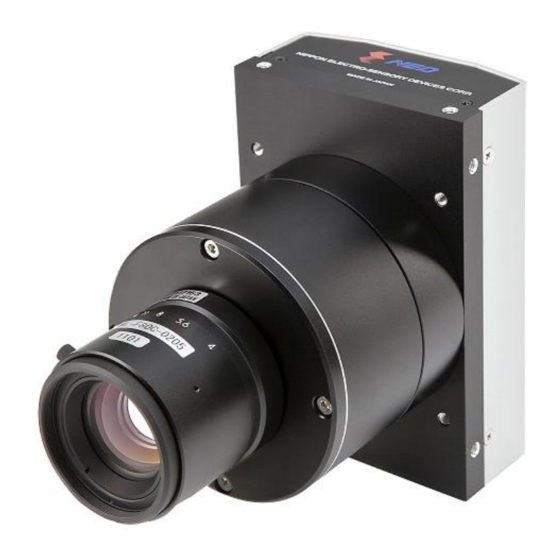
- Page 1 User’s Manual Line Scan Camera Type: XCM80160CXP/60160CXP/40160CXP NIPPON ELECTRO-SENSORY DEVICES CORPORATION...
- Page 2 Directive on Waste Electrical and Electronic Equipment (WEEE) Please return all End of Life NED products to the distributor from whom the product was purchased for adequate recycling and / or disposal. All costs of returning the Product to NED are borne by the shipper.
- Page 3 Introduction Thank you for purchasing NED’s Line Scan Camera. We look forward to your continued custom in the future. For safety use For your protection, please read these safety instructions completely before operating the product and keep this manual for future reference.
- Page 4 Do not share the power supply with motor units or other devices that generate noise interference. Do not disconnect the camera while rewriting the embedded memory. When you change the exposure mode that is set at the NED factory, input control signal (Trigger packet) from the capture board. XCM80160CXP_60160CXP_40160CXP...
- Page 5 Product Warranty Warranty Period The product warranty period, as a general rule, is two years from purchase; however for detailed conditions please contact the sales representative for your region/country. However, in some cases due to the usage environment, usage conditions and/or frequency of use, this warranty period may not be applicable.
- Page 6 Exclusion of Liability for Compensation for Missed Opportunities Regardless of whether within the warranty period or not, our warranty does not cover compensation for missed opportunities for our customers, or our customers’ customers, caused by a fault of our products, nor for damage to products other than our own, or related business.
-
Page 7: Table Of Contents
Table of Contents 1 Product Outline ..............10 1.1 Features ......................10 1.2 Applications ....................10 1.3 Image Sensor ....................12 1.4 Performance Specifications ................12 2 Camera Setting and Optical Interface ........ 15 2.1 Setting Camera ....................15 2.2 Fixing Camera ....................15 2.3 Optical Interface .................... - Page 8 5.3.9 Memory Save .................... 31 5.3.10 Generating Test Pattern ................. 31 5.3.11 Saving Pixel Correction Data..............31 5.3.12 Setting Pixel Correction ................. 32 5.3.13 Setting Exposure Time - Readout Time ..........32 5.3.14 Setting Pixel Readout Direction ............33 5.3.15 Dynamic Range Control (Multi-Slope) Settings ........33 5.4 Digital Processing flow in FPGA..............
- Page 9 9.2 Contact for support ..................57 9.3 Product Support ....................58 UME-0022-02 XCM80160CXP_60160CXP_40160CXP...
-
Page 10: Product Outline
1 Product Outline 1.1 Features CoaXPress interface CXP-2(2.5 Gbps). cable length up to about 100 m High-integrity data Real-time action Up Link trigger semantics Device Discovery GENiCAM correspondence 1.2 Applications Inspection of Transparent panels and PCBs ... - Page 11 An example of Visual Inspection of PCBs is shown below. Line scan camera Figure 1-2-1 Visual Inspection of PCBs Applicable Work COB, BGA and MCM printed circuit boards Performance 1. Maximum board size: 100 mm × 200 mm 2. Resolution: 10 μm 3.
-
Page 12: Image Sensor
1.3 Image Sensor The camera uses a CMOS sensor with a maximum data rate of 160MHz to acquire high responsivity and superior quality images. μ μ The pixel size is 7 XCM80160CXP outputs 8192 pixel data, XCM60160CXP outputs 6144 pixel data, XCM40160CXP outputs 4096 pixel data through a Single CXP-2 CoaXPress interface. - Page 13 PRNU(Photo Response Non Typically 20DN(without correction, at minimum gain) 4DN (with correction, at minimum gain) Uniformity) Random Noise Typically 20DN (peak value at minimum gain) Video output CoaXPress Data/Controller Canare: BCJ-FPC(75Ω) Connectors Power Supply Hirose: HR10A(6Pin) Lens Mount M72x0. 75 Screw Nikon F Mount Operating Temperature (˚C) 0 to 50...
- Page 14 The spectral Responsivity is shown below. (Ta=25℃) 1000 Wavelength (nm) Figure 1-4-1 Spectral Responsivity XCM80160CXP_60160CXP_40160CXP UME-0022-02...
-
Page 15: Camera Setting And Optical Interface
2 Camera Setting and Optical Interface 2.1 Setting Camera Use the M4 screw holes or the screw hole for a tripod to set the camera. An optional mounting base (sold separately) is available. 2.2 Fixing Camera Use the M4 screw holes (4 places at the front, 8 places at the side) to fix the camera. - Page 16 The dimensions for cameras are shown below. 72x0.75 Screw Mount Unit: mm BNC(Canare:BCJ-FPC) Indicator Power Supply Connecor (HIROSE HR10A 6P) DC12-15V C L IS B e e DIGITA LINESCAN CAMERA 4-M4 Depth 6 (Both Sides) Ø 4-M4 Depth 6 (Top,Bottom) 4-M4 Depth 8 (Front Surface) 1/4"-20UNC 1st Pixel M72 x 0.75 Depth 10...
- Page 17 Unit : mm Nikon F Mount Power Supply Connector (HIROSE HR10A 6P) Indicator BNC(Canare BCJ-FPC) DC12-15V CLISBee S DIGITAL LINESCAN CAMERA 4-M4 Depth 6 (Both Sides) 4-M4 Depth 6 1/4"-20UNC (Top, Bottom) 4-M4Depth 6 (Front Surface) 1st Pixel Figure 2-2-2 Dimensions (Nikon F Mount) UME-0022-02 XCM80160CXP_60160CXP_40160CXP...
-
Page 18: Optical Interface
2.3 Optical Interface The lens mount depends on the type of camera. For XCM80160CXP, M72×0.75 screw mount is used. For XCM60160CXP, XCM40160CXP, Nikon F mount is used. The amount and wavelengths of light required to capture useful images depend on the intended use. -
Page 19: Hardware
3 Hardware 3.1 Camera Connection <Single:connection> <Single X 2:connection> CXP cable CXP cable frame Grabber frame Grabber board board Line scan camera Line scan camera object object LED incident lighting LED incident lighting Depending on the frame grabber board, it is possible to connect up to four cameras at the time of [writing]. -
Page 20: Power Supply
The pin assignment of the power supply connector is shown below. Figure 3-2-2 Power Supply Connector (HIROSE : HR10G -7R- 6PB) Round shape push-pull lock type Table 3-2-1 Pin Assignment of Power Supply Connector Name 12-15V 12-15V 12-15V 3.3 Power Supply The camera requires a single power supply (DC+12 to +15V). -
Page 21: Led Indicator Status
3.4 LED Indicator Status Camera Power Supply is off : LED off Camera Booting Up (Power On) : Lights orange Device Discovery : Lights orange for 0.5s Scan rate > ~1.6S* : Blinks orange(except ExtEdge Mode) Low Speed Link disconnected (Cable disconnected) : Lights red Unable to process commands (System crash) : Blinks red Transmitting image packets (Acquisition Start =1) -
Page 22: Camera Startup
4 Camera Startup 4.1 Camera Startup Procedure This camera does not immediately output stream data packets (image data) after powering on. In order to output stream data packets, it is necessary to perform Device Discovery (Camera and Frame Grabber connection). Please check your frame grabber’s manual for how to perform device discovery. -
Page 23: Camera Control
5 Camera Control The camera can be controlled by the frame grabber board through the camera’s control registers. The camera supports GenICam, and so can be easily controlled by a GenICam-compatible frame grabber. The camera control software which came with your frame grabber should be used for camera control. - Page 24 -15...15(1DN/step at 8bit) DigitalOffset 0x0000_A088 -15 to 15 -60...60(4DN/step at 10bit) 0=FreeRun/1=ExtEdge/2=ExtLevel ExposureMode 0x0000_A08C 0 to 3 3=Multi Slope Programmable Exposure Time (See 5.2) ExposureTimeDividing 0x0000_A090 0 to 11 48.8~1676083.2μs (XCM80160CXP) 36.6~1257062.4μs (XCM60160CXP) ExposureTimeCounter 0x0000_A094 61 to 1023 27.1~ 931157.3μs (XCM40160CXP) Exposure-Readout Time (See 5.2)...
-
Page 25: Memory Setup Values (Factory Settings)
5.1.3 Memory Setup Values (Factory Settings) The memory setup values (factory settings) are shown below. Table 5-1-3-1 Memory Setup Values (Factory Settings) Control Item Address VAL1 Control Description Acquisition Start 0x0000_A00C STOP Acquisition Stop 0x0000_A010 STOP Pixel Format 0x0000_A014 0x101 monochrome 8bit Analog Gain 0x0000_A080... -
Page 26: Programmable Exposure Time・Exposure-Readout Time Calculation
5.2 Programmable Exposure Time・Exposure-Readout Time calculation procedure Programmable Exposure Time= (0x0000_A094)÷{[X]÷(16x2^(0x0000_A090))} Exposure-Readout Time= (0x0000_A098) ÷{[X]÷(16x2^(0x0000_A090))} XCM80160CXP [X]=20,000,000 XCM60160CXP [X]=26,666,667 XCM40160CXP [X]=36,000,000 Calculated example of XCM80160CXP Programmable Exposure Time (ExposureTimeDividing) :(0x0000_A090)= 0 Programmable Exposure Time (ExposureTimeCounter) : (0x0000_A094)= 61 : (0x0000_A098)= 10 Exposure-Readout Time(ExposurePadding) Programmable Exposure Time=61÷{20000000÷(16x2^0)} =48.8μsec Exposure-Readout Time=10÷(20000000÷(16x2^0)) =8.0μsec... - Page 27 2. Open the DCF file and the Feature Browser. 3. Control the camera from the Features box. In the case of the Matrox Radient, the list of registers is displayed in the window. Change the settings via the dropdown list or spinners. UME-0022-02 XCM80160CXP_60160CXP_40160CXP...
-
Page 28: Setting Analog Gain
5.3.1 Setting Analog Gain Sets analog gain in 21 steps between x1 and x11.22. ・Register name Analog Gain ・VAL × 1.00 ~ × 11.22 (Example) × 1.84 Analog Gain : Setting analog gain (x1.84)) 5.3.2 Setting Digital Gain Sets digital gain in 512 steps between x1 and x2 Digital Gain : 1023 / (1023 –... -
Page 29: Setting Digital Offset
5.3.3 Setting Digital Offset Sets digital offset -15 to +15(8 bit: 1DN/Step), -60 to +60(10 bit: 4DN/step) ・Register name Digital offset ・VAL -15 ~ +15 (Example) Digital offset: 5 5.3.4 Setting Exposure Mode Sets the exposure mode. ・Register name Exposure Mode ・VAL Free run / External edge / External level/ Multi Slope (Example) -
Page 30: Setting Exposure Time
5.3.5 Setting Exposure Time Sets the exposure time. ・ Register name Exposure Time Dividing ・ VAL 16 ~32768 (Setting Dividing) ・ Register name Exposure Time Counter ・ VAL 61 ~1023 (Setting Counter) (Example) Exposure Time Dividing: 16 Exposure Time Counter: 120 The changes will be reflected in Integration Time and Scanrate. -
Page 31: Memory Initializing (Initializing Camera Settings)
5.3.7 Memory Initializing (Initializing Camera Settings) Reset the flash memory to the factory default. ・ Register name User Set_Reset to Factory Default ・ VAL Execute() 5.3.8 Memory Load (Reads out the camera settings from the flash memory ) Reads out the camera settings from the flash memory ・... -
Page 32: Setting Pixel Correction
5.3.12 Setting Pixel Correction Sets pixel correction. ・ Register name Pixel Correct Set Mode ・ VAL Disable / Factory white / User white (Correction OFF / Factory white correction / User white correction) ・ Register name Pixel Correct Set Level ・... -
Page 33: Setting Pixel Readout Direction
5.3.14 Setting Pixel Readout Direction Sets the pixel readout direction. ・ Register name ReverseX ・ VAL clear the check box(Forward) / check box (Reverse) (Example) Reverse: check box (Reverse) 5.3.15 Dynamic Range Control (Multi-Slope) Settings The following settings control the Multi-Slope function: ・... -
Page 34: Digital Processing Flow In Fpga
5.4 Digital Processing flow in FPGA The figure below shows the digital processing flow in the FPGA. FPGA Processing block diagram Video(10bit) From Sensor Test Pattern Black reference White reference select substract multipl Video(8 or 10bit) To CoaxPress Driver 8 or 10bit Output Block Digital Gain Digital Offset... -
Page 35: Saving And Loading Camera Settings
5.6 Saving and Loading Camera Settings The camera setting data is saved in the internal memory (flash memory) and is loaded from the memory when turning on the power supply or loading. The number of times the flash memory can be rewritten will vary depending on actual operational conditions. -
Page 36: Video Output Format
5.7 Video Output Format The camera outputs 8-bit or 10-bit black and white digital data(Pixel Format : Mono 8 or Mono 10)through Coax Press IF. 8bit(Default) 10bit bit9 bit9 bit8 bit8 bit7 bit7 bit6 bit6 bit5 bit5 8bit 10bit bit4 bit4... -
Page 37: Exposure Mode And Timing Chart
5.9 Exposure Mode and Timing Chart The camera has three exposure modes. The overview of each mode and the timing are as follows. 5.9.1 Free Run Exposure Mode In free-run exposure mode, the camera generates its own internal control signal based on two programmable parameters, exposure time and readout time. -
Page 38: External Trigger Exposure Mode (Trigger Edge)
5.9.2 External Trigger Exposure Mode (Trigger Edge) In external trigger exposure mode (Trigger Edge), the exposure time is determined by setting the control register, and the line period is determined by the external trigger period. Each exposure starts with the rising edge of the trigger pulse. The range of programmable exposure time and the timing chart of the exposure and the readout are shown below. -
Page 39: External Trigger Exposure Mode (Trigger Level)
5.9.3 External Trigger Exposure Mode (Trigger Level) In external trigger exposure mode (Trigger Level), the exposure time is determined by the high trigger pulse time, and the line period is determined by the external trigger period. Each exposure starts with the rising edge of the trigger pulse. The range of programmable exposure time, the timing chart of the exposure and the readout are shown below. -
Page 40: Setting Offset
5.10 Setting Offset In the figure below, the horizontal axis indicates the amount of incident light and the vertical axis indicates the output. Fs shows the output at saturation. Dd shows the output at darkness. (Both Fs and Dd are digital.) Se shows the saturation current, or the amount of exposure when the output saturates. -
Page 41: Setting Gain
5.11 Setting Gain The camera can adjust the analog gain (x1 to x11.2 in 21 steps) and the digital gain. As shown in the figure below, increasing the gain setting increases the gradient of the camera’s response curve and results in a higher camera output for a given amount of light. - Page 42 Gain-Sensitivity is shown below. Table 5-11-1 Gain-Sensitivity Sensitivity Sensitivity Analog Amplifier Analog Amplifier (V/lx・s) (V/lx・s) x1.00 0.00dB x3.74 11.46dB x1.13 1.06dB x4.23 12.52dB x1.28 2.12dB x4.78 13.58dB x1.44 3.18dB x5.40 14.64dB x1.63 4.24dB x6.10 15.70dB x1.84 5.30dB x6.89 16.76dB x2.08 6.36dB x7.78 17.82dB...
-
Page 43: Pixel Correction
5.12 Pixel Correction As a rule, image sensors (CCD, CMOS and so on) have fixed pattern noise and photo response non-uniformity. Lens shading and light sources can also cause non-uniformity. The camera is set to the optimal correction before shipping in order to provide images of the highest grade. -
Page 44: Test Pattern
5.13 Test Pattern This camera can generate a test pattern. Use the test pattern to verify the proper timing and connections between the camera and the frame grabber board. The test pattern(10bit) of XCM80160CXP, XCM40160CXP is as follows. Figure 5-13-1 Test Pattern of XCM80160CXP. XCM40160CXP Figure 5-13-2 Test Image of XCM80160CXP. - Page 45 The test pattern of XCM60160CXP is as follows. Figure Test Pattern of XCM60160CXP 5-13-3 Figure Test Image of XCM60160CXP 5-13-4 The test pattern is a ramp from 0 to 1023DN, and then from 0 to 511DN in 10-bit mode, then starts at 0 again. The pattern repeats 4 times. UME-0022-02 XCM80160CXP_60160CXP_40160CXP...
-
Page 46: Confirming Camera Settings
6 Confirming Camera Settings 6.1 Before Power-on ① Confirm the pin assignment of the power cable. NAME 12~15V 12~15V 12~15V Figure Pin Assignment of Power Cable 6-1-1 ② Confirm the direction and the channel of the cables. Some Camera Link cables are directional. -
Page 47: After Power-On
(In the case of the Matrox Radient eV-CXP there are 4 connectors, and 4 cameras can be connected) (CANARE BCJ-FPC) Indicator Power Supply Connector (HIROSE HR10A 6P) CXP #0 CXP #1 DC12-15V CXP #2 CXP #3 C LIS Bee S DIGITA L LINESCA N CAMERA Figure... -
Page 48: During Operation
6.3 During Operation (1) Does an acquisition time out error occur? <Cause> <1> Captured images are too large. If there are many filtering processes, the assignments to the driver may be insufficient. <2> The cable is detached from the connector Ensure that the power cable and coaxial cables are connected to the camera firmly. -
Page 49: 7 Dynamic Range Control (Multi-Slope Mode)
7 Dynamic Range Control (Multi-Slope Mode) By setting the “ExposureMode” register to “Multi Slope”, it is possible to change the slope of the photoelectric conversion curve at multiple points in order to increase the dynamic range of captured images. In this mode, the registers “MultiSlope_Level1, 2, 3” set the knee point levels of the linear response, and “MultiSlope_Timing 1, 2, 3”... - Page 50 After the second reset, the line characteristics change such that it bends at the pink and green points (shown in the figure above right). In the case of the blue line in the figure above left, without Multi-slope, the photoelectric conversion function is a straight line to A’, and the camera is saturated with incident light.
-
Page 51: Standard Mode
[The following guide uses the XCM80160CXP as an example] 7.2 Standard Mode The minimum line period is 53.6 μsec. The dynamic range is determined by the sensor’s saturation output and dark output. The sensor specification is 60dB. UME-0022-02 XCM80160CXP_60160CXP_40160CXP... -
Page 52: When Bending The Response Curve
7.3 1 When bending the response curve ① To set the integration time ratio of each slope to 10, use the following settings: ExposureMode: MultiSlope MultiSlope_Level1: 0, MultiSlope_Level2: 0, MultiSlope_Level3: 8 MultiSlope_Timing1: 0, MultiSlope_Timing2: 0, MultiSlope_Timing3: 10 ExposureTimeDividing: 16 ExposureTimeCounter: 110 As can be seen in the figure below, the integration time of the first slope will be 100 (110-10), the integration time of the second slope is 10, and the reset level is half the saturation level. - Page 53 ②To set the integration time ratio of each slope to 5, use the following settings: ExposureMode: MultiSlope MultiSlope_Level1: 0, MultiSlope_Level2: 0, MultiSlope_Level3: 8 MultiSlope_Timing1: 0, MultiSlope_Timing2: 0, MultiSlope_Timing3: 11 ExposureTimeDividing: 16 ExposureTimeCounter: 66 As can be seen in the figure below, the integration time becomes 55 in the first slope, 11 in the second slope, and the reset level is half the saturation level.
-
Page 54: Bending The Line Three Times
7.4 Bending the line three times ① For an integration time ratio of 10, use the following settings: ExposureMode:「Multi Slope」 MultiSlope_Level1:4, MultiSlope_Level2 :8, MultiSlope_Level3 :12 MultiSlope_Timing1:1, MultiSlope_Timing2:10, MultiSlope_Timing3:100 ExposureTimeDividing :16 ExposureTimeCounter:1023 The integration time becomes 1000 in the first slope, 100 in the second slope, 10 in the third and 1 in the fourth. - Page 55 ② For an integration time ratio of 5, use the following settings: ExposureMode:「Multi Slope」 MultiSlope_Level1:4, MultiSlope_Level2 :8, MultiSlope_Level3 :12 MultiSlope_Timing1:1, MultiSlope_Timing2:5, MultiSlope_Timing3:25 ExposureTimeDividing :16 ExposureTimeCounter:156 The integration time becomes 125 (156-(1+5+25) in the first slope, 25 in the second slope, 5 in the third slope and 1 in the fourth slope. The respective reset levels become ¼, ½, ¾...
-
Page 56: Sensor Handling Instructions
8 Sensor Handling Instructions 8.1 Electrostatic Discharge and the Sensor CMOS sensors are susceptible to damage from electrostatic discharge and can deteriorate as a result. Take care when handing the sensor. 8.2 Protecting Against Dust, Oil and Scratches The CMOS sensor window is part of the optical path and should be handled like other optical components with care. -
Page 57: Others
The contents of this document are subject to change without prior notice. Every care has been taken in the preparation of this User’s Manual. If you should discover any errors or omissions, please notify your nearest NED representative. 9.2 Contact for support Nippon Electro-Sensory Devices Corporation... - Page 58 9.3 Product Support If there is a problem with your camera after checking it, turn off the power and call your NED representative. XCM80160CXP_60160CXP_40160CXP UME-0022-02...
- Page 59 Revision History Revision Date Changes Number 22 Mar. 2013 Initial release 13 Mar. 2014 XCM40160CXP ExposurePaddind value UME-0022-02 XCM80160CXP_60160CXP_40160CXP...
Need help?
Do you have a question about the CoaXpress XCM80160CXP and is the answer not in the manual?
Questions and answers