
Related Manuals for NED XCM6040SAT2


Summary of Contents for NED XCM6040SAT2
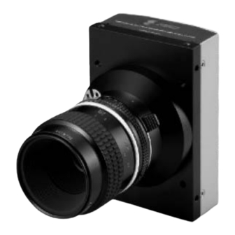
- Page 1 User’s Manual Line Scan Camera Type:XCM6040SAT2 NIPPON ELECTRO-SENSORY DEVICES CORPORATION...
- Page 2 Equipment itself. *Class A equipment is equipment suitable for use in all establishments other than domestic and those directly connected to a low voltage power supply network which supplies buildings used for domestic purposes. XCM6040SAT2 UME-0007-01...
-
Page 3: Safety Precaution
Introduction Thank you for purchasing NED’s Line Scan Camera. We look forward to your continued custom in the future. For safety use For your protection, please read these safety instructions completely before operating the product and keep this manual for future reference. - Page 4 Do not share the power supply with motor units or other devices that generate noise interference. Do not disconnect the camera while rewriting an embedded memory. When you change exposure mode that is set at NED factory, input control signal (CC1) from the capture board. XCM6040SAT2...
- Page 5 The manufacturer assumes no responsibility for any damages resulting from malfunctions caused by combined use of this product with other peripheral equipment. The manufacturer assumes no responsibility for damages resulting from malfunctions caused by non-authorized repair or modifications made to this product. UME-0007-01 XCM6040SAT2...
-
Page 6: Table Of Contents
4.2.4 Setting Exposure Mode..................27 4.2.5 Setting Exposure Time..................27 4.2.6 Setting Output Signals 1 (Setting Data Format)..........28 4.2.7 Setting Output Signals 2 (Setting Linear / Log) ..........28 4.2.8 Memory Initializing (Initializing Camera Settings) ......... 28 XCM6040SAT2 UME-0007-01... - Page 7 5.3 In Operation ......................51 6 Sensor Handling Instructions ..........52 6.1 Electrostatic Discharge and the Sensor..............52 6.2 Protecting Against Dust, Oil and Scratches ............52 6.3 Cleaning the Sensor Window ................. 52 7 Troubleshooting ................53 UME-0007-01 XCM6040SAT2...
- Page 8 ........................71 9.1 Operation in the factory default value ..............71 9.2 normal mode......................73 9.3 when you curve it one time ..................73 9.4 when you curve it three times................75 10 Others ....................77 10.1 Notice ........................77 XCM6040SAT2 UME-0007-01...
- Page 9 10.2 Contact for support....................77 10.3 Product Support ....................78 Revision History ..................79 UME-0007-01 XCM6040SAT2...
-
Page 10: Product Outline
Using random access reading, High speed inspection becomes possible because only the required data is being transferred. This camera utilizes an Intelligent Transportation System Outdoor surveillance Wide dynamic range prevents the camera from saturation caused by direct rays and specular refection rays. XCM6040SAT2 UME-0007-01... - Page 11 2. Resolution: 10μm 3. Inspection time: less than 30 seconds Unit Configuration 1. Camera: Line scan camera 2. Controller: Dedicated software for PC system 3. Size: L930 x D500 x H500 (mm) Applicable Fields Inspection of patterns on film PCBs UME-0007-01 XCM6040SAT2...
-
Page 12: Image Sensor
The Performance Specifications are shown in Table 1-4-1. It shows the data when the camera is operating at maximum scan rate, unless otherwise specified. Table 1-4-1 Performance Specifications Specifications Items XCM6040SAT2 Number of Pixels 6144 Pixel Size H x V (μm) 7x7 Sensor Length (mm) 43.008... - Page 13 *2) DN : Digital Number (10bit : 0 -1023) *3) This product is designed and manufactured in accordance with the following standards. EN 55011:1998+A1:1999+A2:2002 Group 1 Class A EN 61000-6-2:2005 FCC Part 15 Subpart B:2006 Class A *4) Measurements were made at room temperature. UME-0007-01 XCM6040SAT2...
-
Page 14: Camera Setting And Optical Interface
8mm, and less than 6mm for the side. No X-, Y-axis orientation and tilt adjustment mechanism is available. Please prepare an adjustment mechanism if required. XCM6040SAT2 UME-0007-01... - Page 15 Unit : mm Nikon F Mount Indicator Connector(MDR26) (HIROSE HR10A 4P) DC12-15V CLISBee S DIGITAL LINESCAN CAMERA 4-M4 Depth 6(Both Sides) 4-M4 Depth 6 1/4"-20UNC (Top,Bottom) 4-M4 Depth 6 (Front Surface) 1st Pixel Figure 2-2-1 Dimensions of the Camera UME-0007-01 XCM6040SAT2...
-
Page 16: Optical Interface
2.3 Optical Interface For XCM6040SAT2 the Nikon F-mount is available. The amount and wavelengths of light required to capture useful images depend on the intended use. Factors include the property, speed, the objects spectral characteristics, exposure time, the light source characteristics, the specifications of the acquisition system and so on. - Page 17 Figure 3-1-1 Connections between Camera and Frame Grabber Board and Power Supply There are two connectors available for the Camera Link Base Configuration board according to the manufacturer. Always check the frame grabber board specifications before making connections. UME-0007-01 XCM6040SAT2...
-
Page 18: Input / Output Connectors And Indicator
3.2 Input / Output Connectors and Indicator The layout of input /output connecters and the LED indicator are as follows. Camera Link Power Supply Connector Indicator Connector (MDR26) (HIROSE HR10A 4P) DC12-15V CLISBee S DIGITAL LINE SCAN camera Figure 3-2-1 Input/Output Connectors and Indicator XCM6040SAT2 UME-0007-01... -
Page 19: Connectors・Pin Assignments・Cables
SerTFG SerTFG± SerTFG± SerTC 100Ω SerTC± SerTC± 100Ω LVDS_DRIVER(NS) LVDS_RECEIVER(NS) DS90LV047AT DS90LV048AT equivalent recommended CC1(control input) CC1± CC1± CC2 100Ω CC2± CC2± CC3 100Ω CC3± CC3± CC4 100Ω CC4± CC4± 100Ω Figure 3-3-1 Camera / Frame Grabber Interface UME-0007-01 XCM6040SAT2... - Page 20 The camera has 26-pin MDR connectors for control signals of Camera Link, data signals and serial communications. The camera also has a 4-pin HIROSE connector for power supply. Figure 3-3-3 Camera Link Connector Half pitch (miniature half ribbon) shape Locking screw (UNC #4-40) type XCM6040SAT2 UME-0007-01...
- Page 21 3M :14B26 -SZLB - xxx - 0LC by or equivalent To avoid uncoupling of the cable connectors during power on, make sure to clamp them with the locking screws. Do not unplug the cables while power is being supplied to the camera. UME-0007-01 XCM6040SAT2...
-
Page 22: Power Supply
LED lamp illuminates when +12V to +15V power is being supplied to the camera. If the lamp fails to illuminate even after power is switched on, turn OFF power immediately. Inspect wiring. Check the voltage and capacity of the supplied power source. XCM6040SAT2 UME-0007-01... -
Page 23: Camera Control
Format 4 CMD VAL1 VAL2 VAL3 CR CMD: Control text (3 Bytes) Use 3 lowercase letters only. No numerals allowed. Carriage Return (0x0D) Space (0x20) or Comma (0x2C) VAL: Setting value (decimal, maximum 5 digits) <Example> gax 0 CR UME-0007-01 XCM6040SAT2... -
Page 24: Camera Sending Message (Pc Receiving Message)
>OK CR >gax 0 CR EOT Table 4-1-3-1 Error Messages Camera Response Meaning Camera executed command CMD ERR! Command is not valid CMD OVR ERR! Command text line is too long VAL ERR! Parameter accepted was outside of specified MEM ERR! Memory error XCM6040SAT2 UME-0007-01... -
Page 25: Camera Control Commands
0 is the most high level and 15 0 to 15 0 to 15 0 to 15 is the most low level. Multi-slope time setting 0 to 511 0 to 511 0 to 511 See 4.2.18 Programmable Exposure Time=VAL2÷{40000000÷(16x2^VAL1)} UME-0007-01 XCM6040SAT2... -
Page 26: Memory Setup Values (Factory Settings)
4.2 Details on Commands 4.2.1 Setting Analog Gain Sets analog gain in 21 steps between x 1 and x 11.2. Format 2 CMD VAL1 CR 0 (x1) to 20 (x11.2) <Example> gax 5 CR (Setting analog gain 5(x1.84)) >OK >gax 5 XCM6040SAT2 UME-0007-01... -
Page 27: Setting Digital Gain
4.2.4 Setting Exposure Mode Sets the exposure mode. Format 2 CMD VAL1 CR 0,1,2,3 <Example> inm 0 CR (Setting the exposure mode free run) >OK >inm 0 4.2.5 Setting Exposure Time Sets the exposure time. Format 3 CMD VAL1 VAL2 CR UME-0007-01 XCM6040SAT2... -
Page 28: Setting Output Signals 1 (Setting Data Format)
Format 2 CMD VAL1 CR 0,1 (0:linear output / 1:log output) <Example> voc 0 CR (linear output) >OK >voc 0 4.2.8 Memory Initializing (Initializing Camera Settings) Reset the flash memory to the factory default. Format 1 CMD CR <Example> XCM6040SAT2 UME-0007-01... -
Page 29: Memory Load
>rev 0 >rst 4.2.9 Memory Load Reads out the camera settings from the flash memory. Format 1 CMD CR <Example> rfd CR >OK >Type= XCM6040SAT2 >Ver.= 2.36_0x4425 >Serial=0 >check_code = 20070615 >gax 0 >gdx 0 >odx 0 >inm 0 >int 1,61... -
Page 30: Memory Save
>OK >tpn 1 4.2.12 Saving Pixel Correction Data Acquires the current pixel correction data and saves it in the flash memory. One correction data can be saved at each step of analog gain. Format 1 CMD CR <Example> XCM6040SAT2 UME-0007-01... -
Page 31: Setting Pixel Correction
VAL1 (in “pad”)=1, the increment is 12.5ns x 2 x 16 x (2 x 2 x 2)=3.2 μs. And VAL1 (in “int”)=5 and VAL1 (in “pad”)=1, the increment is 12.5ns x 2 x 16 x (2 x 2 x 2 x 2 x 2)= 12.8 μs. UME-0007-01 XCM6040SAT2... -
Page 32: Returning The Cameras Settings To The Its Original Status
4.2.15 Returning the Cameras Settings to the its original status Returns the current camera settings. Format 1 CMD CR <Example> sta CR >OK >Type=XCM6040SAT2 >Ver.=2.36_0x4425 >Serial=0 >check_code = 20070615 >gax 0 >gdx 0 >odx 0 >inm 0 >int 1,61 >cka 0 >voa 0,0... -
Page 33: Multi-Slope Level Setting
( See section 9 ) CMD □ VAL1 □ VAL2 □ VAL3 CR Format VAL1 0 ~ 512 VAL2 0 ~ 512 VAL3 0 ~ 512 ( ) Example mst□0□1□10 CR >OK >mst 0,1,10 UME-0007-01 XCM6040SAT2... -
Page 34: Internal Circuit Configuration Block
(sending the “rfd” command). The number of times the flash memory can be rewritten will vary depending on actual operational conditions. After turning on the power supply, XCM6040SAT2 UME-0007-01... -
Page 35: Serial Communication Settings
Serial communication is performed through the Camera Link Interface Table 4-6-1 shows serial communication settings. Table 4-6-1 Serial Communication Settings Parameter Items Setup Value Communication Speed (Baud rate) 9600bps Data Length 8bit Parity Bit None Stop bit 1bit Flow Control None UME-0007-01 XCM6040SAT2... -
Page 36: Video Output Format
b it1 b it1 b it0 b it0 Figure 4-7-1 Pin Assignments of Digital Data The A/D converter of the camera has a 10-bit resolution. For 8-bit output, the upper 8-bit signal can be output as a video data. XCM6040SAT2 UME-0007-01... - Page 37 Invalid Invalid Invalid Invalid 6141 6143 Invalid Invalid Invalid Invalid (#1TAP VIDEO Invalid Invalid Invalid Invalid 6142 6144 Invalid Invalid Invalid Invalid (#2 TAP FVAL = 0 (low level) fixed Figure 4-7-2 Video Output Phase of the Camera UME-0007-01 XCM6040SAT2...
-
Page 38: Exposure Mode And Timing Chart
Table 4-8-1-1 Programmable Exposure Time 6040SAT2 p Programmable exposure time 73.2 - 1,257,140.97 76.8 r Readout time (unit:μs) scan Exposure Readout Figure 4-8-1-1 Free Run Exposure Mode The data of Exposure (1) is read out at Readout (1) XCM6040SAT2 UME-0007-01... -
Page 39: External Trigger Exposure Mode (Trigger Edge)
Trigger pulse H time ≧1.6 b Trigger pulse L time ≧7.2 ≧80.4 c Trigger pulse cycle (unit:μs) Trigger (CC1) Exposure Readout Figure 4-8-2-1 External Trigger (Trigger Edge) Exposure Mode The data of Exposure (1) is read out at Readout (1) UME-0007-01 XCM6040SAT2... -
Page 40: External Trigger Exposure Mode (Trigger Level)
High trigger pulse time ≧76.8 b Low trigger pulse time ≧3.6 c Trigger pulse period ≧80.4 (unit:μs) Trigger (CC1) Exprosure Readout Figure 4-8-3-1 External Trigger (Trigger Level) Exposure Mode The data of Exposure (1) is read out at Readout (1) XCM6040SAT2 UME-0007-01... -
Page 41: Setting Offset
By setting the offset, you can set the Y-intercept arbitrarily. DF shows the digital offset value. The gradients of lines do not change. DF : Offset Value Output Volume of Light (lx・s) Figure 4-9-2 Offset Adjustment Adjust gain and offset to meet your system’s requirements. UME-0007-01 XCM6040SAT2... -
Page 42: Setting Gain
(a<b<c) Fs Gain a Gain b Gain c Amount of Incident Light (lx.s) Figure 4-10-1 PGA Gain Adjustment Gain and noise values are proportionally related. Adjust amount of gain in accordance with the requirements of your camera system. XCM6040SAT2 UME-0007-01... - Page 43 You can choose between Linear or Log mode for the cameras output A/D Characteristics by sending the “voc” command. The characteristics are shown in Figure 4-10-2. LOG ADC LIN ADC Amount of Incident Light Figure 4-10-2 A/D Characteristics UME-0007-01 XCM6040SAT2...
-
Page 44: Pixel Correction
(10bit digital) Vin :Input data (digital) Vout :Output data (digital) The corrected data is expressed in the following equation. Vout=(Vin-Cal_bl) x Target_val / (Cal_wh-Cal_bl) Waveform before bit correction Output Pixel Number Waveform after bit correction Output Pixel Number Figure 4-11-1 Waveform before and after bit correction XCM6040SAT2 UME-0007-01... -
Page 45: Command Settings
(3) Confirm that the camera returns “>OK” and “>wht”. Thus arbitrary white correction data is saved and loaded to the camera. (4) Send the “shc 2 VAL2” command through serial communication. Then the arbitrary white correction will be on and set the correction level as “VAL2”. UME-0007-01 XCM6040SAT2... -
Page 46: Test Pattern
The test pattern of the camera is below. Figure 4-12-1 Test Pattern of the Camera Figure 4-12-2 Test Image the Camera The test pattern is a ramp from 0 to 1023DN in 10-bit mode, and then it repeats itself from 0 again 4 times. XCM6040SAT2 UME-0007-01... -
Page 47: Confirming Camera Settings
(2) Confirm the direction and the channel of the cables. Some Camera Link cables are directional. If one of the connectors says “Camera side”, connect it to the camera. Camera side Frame grabber side 32.5 Cable Length Figure 5-1-2 Connection Direction of Camera Cable UME-0007-01 XCM6040SAT2... -
Page 48: After Power-On
Figure 5-1-3 Channel of Camera Link Cables 5.2 After Power-on (1) Confirm sent and received commands using the camera control utility. Launch CLISBeeCtrl, set COM port and connect. Click “Memory Dump” and wait for the response. Figure 5-2-1 Confirmation of Connection XCM6040SAT2 UME-0007-01... - Page 49 (2) Set a trigger mode and a video output mode with the camera control utility. Example: Trigger mode = Free run Video output mode =8bit Figure 5-5 Setting of Exposure Mode (Trigger Mode) and Video Output Mode If you have your own application to check the images, select suitable settings. UME-0007-01 XCM6040SAT2...
- Page 50 (3) Capture images using a camera interface board utility. In case of Matrox’s Solios, it is convenient to use Intellicam. Figure 5-2-3 Solios Intellicam dcf Window XCM6040SAT2 UME-0007-01...
-
Page 51: In Operation
(2) Are there dark lines in the direction of vertical scanning on the image? <Cause> <1> Dust on the sensor window Dust may come on the sensor window from the inside or the outside of the camera. Remove the dust with air or a lens cleaner. UME-0007-01 XCM6040SAT2... -
Page 52: Sensor Handling Instructions
Oil : Wipe the window with a lint-free cloth wiper moistened with ethyl alcohol carefully and slowly. When there is dust or smudges on the sensor window, it appears in the same way as noise on the image. Please remove it appropriately. XCM6040SAT2 UME-0007-01... -
Page 53: Troubleshooting
The sample software program is used to with the camera control the camera and is communicating successfully. To next page with the camera successfully. To next page To next page Confirm the communication software, the control protocol for the camera and commands. UME-0007-01 XCM6040SAT2... - Page 54 The optical axes of the camera and Check the light source. If the the image sensor are aligned. images are too dark, try to increase the light intensity, and vice versa. The camera could be faulty. Please contact us for assistance. XCM6040SAT2 UME-0007-01...
-
Page 55: When Noise Is Present In The Image
(attached to a machine which applies stress to the cables). Check the condition of the camera cables and the power supply cable. The camera could be faulty. Please contact us for assistance. To next page UME-0007-01 XCM6040SAT2... - Page 56 Use a stable power supply. When the camera gain is on a high level, bright spots occur without incident light. The camera could be faulty. Please Secondary radiation (rays) contact us for assistance. could cause bright spots, but this is not malfunction. XCM6040SAT2 UME-0007-01...
-
Page 57: When The Camera Becomes Hot
Allow sufficient air circulation around the camera to give it the longer life. Keep the ambient temperature within the range of the specifications. The camera could be faulty. Please contact us for assistance. UME-0007-01 XCM6040SAT2... -
Page 58: Clisbeectrl
8 CLISBeeCtrl 8.1 Overview The CLISBeeCtrl is the remote control software for “CLISBee*” camera using “NED Camera Control Protocol”(NCCP) from a PC. Connectable interfaces are following. 1) Camera Link API 2) Communication Port (COM port, RS232C) *CLISBee is the nickname for XCM series camera. -
Page 59: Operation
Open Windows Explorer and Double-click the “CLISBeeCtrl.exe”. A B C D E Buttons in the tool-bar have the following functions. A: Exporting parameters in the text file format. B: Connection with the camera. C: Disconnection. D: Setting Communication. E: Version Information. UME-0007-01 XCM6040SAT2... -
Page 60: Selecting Interface And Timeout Setting
8.5.2 Selecting interface and Timeout setting 8.5.2.1.Selecting interface 1) Click button D. 2) Select the interface in Drop-down-list-box. 3) Click “Setting” button to set the interface. (See 8.5.2.2. and 8.5.2.3.) 4) Click “OK” button. XCM6040SAT2 UME-0007-01... - Page 61 Note: The camera can be used without this operation after it has been set up correctly. 8.5.2.2 Setting Communication port 1) Set up each item as follows. ( NED standard ) However, when the setup which differs to the camera to connect is shown, follow there.
- Page 62 Note: DLL for Camera Link API is provided by the manufacturer of the grabber board. Some frame grabber boards are connected directly to the PC’s COM port, in this case, select interface to COM port (RS232C). Please contact the manufacturer of the grabber board for detail. XCM6040SAT2 UME-0007-01...
-
Page 63: Connect
Note: The camera can be used without this operation after it has been set up correctly. 8.5.3.Connect Click button B. Then you can control the camera. (See “8.6.Control”) Click the “Memory Dump” button to acquire the current data of the camera. UME-0007-01 XCM6040SAT2... -
Page 64: Disconnect And End Program
8.5.4.Disconnect and end program Click button C. Then click “X” button in the upper right of the window. 8.5.5.Check of the contents of communication Click "Console" tag near the bottom window. XCM6040SAT2 UME-0007-01... -
Page 65: Export Parameters To Text File
2) Input file name and click “Save” button. Present setting value of each control is saved by text format. 8.5.7.Import Parameters from text file 1) Select menu “File” – “Text Load” 2) Input file name and click “Open” button. Each command preserved in the text file is issued one by one. UME-0007-01 XCM6040SAT2... -
Page 66: Control
Note: XCMx0x0SA does not use ‘Analog 2’.( Included to ‘Analog 1’ ) Digital : Set a value with the slider, the edit-box or the spin-button. Then, click “Send” button. < Offset > Digital : Set a value with the slider, the edit-box or the spin-button. Then, click “Send” button. XCM6040SAT2 UME-0007-01... -
Page 67: Clock & Integration
Scanrate -> Counter Calculating : Set the value in the edit-box. Then, click this button. Put the desirable scan rate value, then the counter value will be calculated automatically with the present values of clock, dividing and padding. UME-0007-01 XCM6040SAT2... -
Page 68: Trigger & Video
The selection of Free Run Exposure mode and External Trigger Exposure mode. Video output : The selection of the number of the output bit and the output block. ADC Characteristic : The selection of the A/D characteristics. Direction of scanning : The selection of the scan direction. XCM6040SAT2 UME-0007-01... -
Page 69: Intelligence
Read the data from the camera’s work memory. Flash Load : Loading the data from the camera’s flash memory. Flash Save : Saving the data in the camera’s flash memory. Flash Initialize : Initializing the camera’s flash memory with the factory standard data. UME-0007-01 XCM6040SAT2... -
Page 70: Upgrade
2) Reverse engineering, decompiling, disassembling and modifying without notice the part or all of this software is prohibited.. 3) The specification of this software and the contents of this book may be changed without announcement in future. XCM6040SAT2 UME-0007-01... -
Page 71: The Dynamic Range Control (The Multi-Slope Mode)
2/3 of the saturated level cut off any more, B~E are no change in second times reset. 4) Camera stops exposure in exposure time 61. ♦ The exposure time is different depending on the model. UME-0007-01 XCM6040SAT2... - Page 72 “C’” to “C”. (The light exposure of pink and red in this case no needs to change.) You can work out the wide dynamic range as a result of handling as signal without saturating by using Multi Slope, if large exposure amounts instead of normal. XCM6040SAT2 UME-0007-01...
-
Page 73: Normal Mode
61.9 μ sec ( 8192 pixels 240MHz version), 92.8 μ sec ( 8192 pixels 160MHz version ) . Because the dynamic range is 5.5 times one (the ratio of amount of saturation exposure : 0.55/0.1), it becomes 75dB. (60dB+20log5.5=74.8) UME-0007-01 XCM6040SAT2... - Page 74 0.05+0.25=0.3. Because the dynamic range is 3 times one (the ratio of amount of saturation exposure : 0.3/0.1), it becomes 69.5dB. (60db+20log3=69.5) 1023 The second slope The first slope 0.05 0.25 Amount of saturation exposure light exposure (lux・sec) XCM6040SAT2 UME-0007-01...
-
Page 75: When You Curve It Three Times
129.6 μ sec ( 8192 pixels 160MHz version ) . Because the dynamic range is 39 times one (the ratio of amount of saturation exposure : 3.9/0.1), it becomes 92dB. ( 60db + 20log39 = 91.8 ) You can reset other settings as much as like this. UME-0007-01 XCM6040SAT2... - Page 76 1023 The fourth slope The third slope The second slope The first slope 0.025 0.13 0.775 Amount of saturation exposure light exposure(lux・sec) XCM6040SAT2 UME-0007-01...
-
Page 77: Others
Contents of this document are subject to change without prior notice. Every care has been taken in the preparation of this User’s Manual. If you should discover any errors or omissions, please notify your nearest NED representative. 10.2 Contact for support... -
Page 78: Product Support
If there is still a problem with your camera after checking it in accordance with the troubleshooting guide, turn off the power and call your NED representative. In such case, please inform us of the status of the camera. You can get the status by (1) executing the “sta”... -
Page 79: Revision History
Revision History Revision Number Date Changes 14 Apr.2010 Initial release UME-0007-01 XCM6040SAT2...
Need help?
Do you have a question about the XCM6040SAT2 and is the answer not in the manual?
Questions and answers