
Related Manuals for NED NUCLi7370AT6


Summary of Contents for NED NUCLi7370AT6
- Page 1 User’s Manual Line Scan Camera Type:NUCLi7370AT6 NIPPON ELECTRO-SENSORY DEVICES CORPORATION...
- Page 2 Directive on Waste Electrical and Electronic Equipment (WEEE) Please return all End of Life NED products to the distributor from whom the product was purchased for adequate recycling and / or disposal. All costs of returning the Product to NED are borne by the shipper.
- Page 3 Introduction Thank you for purchasing NED’s Line Scan Camera. We look forward to your continued custom in the future. For safety use For your protection, please read these safety instructions completely before operating the product and keep this manual for future reference.
- Page 4 Design the system configuration so that a loop will not be formed by the ground potential differential. Do not disconnect the camera while rewriting the embedded memory. When you change the exposure mode that is set at the NED factory, input control signal (CC1) from the capture board. NUCLi7370AT6...
- Page 5 As a general rule, in the first instance fault diagnosis should take the form of a telephone call or an email to enable us to assess the circumstances of the malfunction. However, depending on the customer’s requests, we, or our agent, may require an additional fee for this service. UME-0069-03 NUCLi7370AT6...
- Page 6 On request, arrangements can be made separately. Scope of Repair Service The above assumes business dealings and usage to take place in the customer’s region / country. In cases of business dealings and/or usage outside the customer’s region/country, separate consultation is required. NUCLi7370AT6 UME-0069-03...
-
Page 7: Table Of Contents
4.2.12 Pixel Correction Data Import ..................35 4.2.13 Pixel Correction Data Save ..................... 35 4.2.14 Pixel Correction Reference Setting ................35 4.2.15 Pixel Correction Mode ..................... 36 4.2.16 Exposure Mode ........................ 36 4.2.17 Programmable Exposure Time Setting ................. 36 UME-0069-03 NUCLi7370AT6... - Page 8 6.1 No Image ........................... 53 6.2 Noise on Image ......................... 55 6.3 Camera becomes hot ....................... 57 7 Others ........................58 7.1 Notice ............................58 7.2 Contact for support ........................58 7.3 Product Support ........................59 Revision History ......................61 NUCLi7370AT6 UME-0069-03...
-
Page 9: Features
Color identification and inspection of foreign material Inspection of sheet film Inspection of wood surface An example of Visual Inspection of PCBs is shown below. Power Supply PCB pattern LED incident lighting Figure 1-2-1 Visual Inspection of PCBs UME-0069-03 NUCLi7370AT6... -
Page 10: Image Sensor
17.5 / 57 (at 6-tap output) Maximum Scan Rate 11.3 / 88 (at 3-tap output) (kHz) / (μs) In Pseudo-exposure control mode 8.7 / 114 Saturation Exposure ( lx ・ s ) 0.0384 (typically) [Minimum Gain, Daylight Fluorescent Light] NUCLi7370AT6 UME-0069-03... - Page 11 9. 8 or 10 bits Video Output 10. Scan Direction Switching 11. Test Pattern Output *1 : The CCD image sensor used in this camera has high power consumption. Use the camera in the environment that the temperature of the camera front panel surface UME-0069-03 NUCLi7370AT6...
- Page 12 50℃. The spectral Responsivity is shown below. (Ta=25℃) 1 0 0 4 0 0 5 0 0 6 0 0 7 0 0 Wavelength(nm) Figure 1-4-1 Spectral Responsivity NUCLi7370AT6 UME-0069-03...
-
Page 13: Camera Setting And Optical Interface
The dimensions for the cameras are shown below. 23.8 4-M4.0 カメラ固定用 for fixing camera Image plane 結像面 NUCLi7370A RAINBOW series NIPPON ELECTRO-SENSORY DEVICES CORP. DC 12V IN MADE IN JAPAN Unit : mm 単位:mm Figure 2-3-1 Dimensions(M84.5 Mount) UME-0069-03 NUCLi7370AT6... -
Page 14: Optical Interface
CCD image sensors are sensitive to infrared (IR). We recommend using daylight color fluorescent lamps that have low IR emissions. If you use a halogen light source, to prevent infrared from distorting the images use an IR cutoff filter that does not transmit IR wavelengths. NUCLi7370AT6 UME-0069-03... -
Page 15: Hardware
Other than the above, a personal computer, a frame grabber board, a photographic lens, a photographic lens mount, a light source and an encoder are necessary, depending on the situation. Line Scan Camera NUCLi7370AT6 PC Camera Link Cable 3M:14B26-SZLB-xxx-0LC... - Page 16 We recommend you perform a connection test in advance. Table 3-1-1 calculated value of maximum cable length Solios model clock speed(MHz) maximum cable length (m) SOL 6M CL E* (20~66MHz) SOL 6M FC E* (20~85MHz) NUCLi7370AT6 UME-0069-03...
-
Page 17: Input / Output Connectors And Indicator
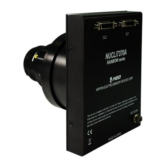
The layout of input /output connecters and the indicator lamp are as follows. Camera Link コネク (MDR26) Camera Link Connector (MDR26) NUCLi7370A RAINBOW series NIPPON ELECTRO-SENSORY DEVICES CORP. DC 12V IN MADE IN JAPAN Indicator インディケータ Power Supply Connector 電源コネクタ (HIROSE HR10G-7R-6P) Figure 3-2-1 Input/Output Connectors and Indicator UME-0069-03 NUCLi7370AT6... -
Page 18: Connectors・Pin Assignments・Cables
Y3± 100Ω CK70MHz YClk± YClk± 100Ω Cable 100Ω terminated 100Ω 100Ω 100Ω 100Ω terminated 100Ω 100Ω Figure 3-3-1 Camera / Frame Grabber Interface The table below shows the Camera Link port assignments for 8-bit 6-tap or 10-bit 6-tap NUCLi7370AT6 UME-0069-03... - Page 19 Port H0 - Port D1 Port H1 - Port D2 Port H2 - Port D3 Port H3 - Port D4 Port H4 - Port D5 Port H5 - Port D6 Port H6 - Port D7 Port H7 - UME-0069-03 NUCLi7370AT6...
- Page 20 The camera has 26-pin MDR connectors for control signals of Camera Link, data signals and serial communications. The camera also has a 4-pin HIROSE connector for power supply. Figure 3-3-3 Camera Link Connector Half pitch (miniature half ribbon) shape Locking screw (UNC #4-40) type NUCLi7370AT6 UME-0069-03...
- Page 21 Serial data input (LVDS) SerTFG+, SerTFG- : Serial data output (LVDS) CC1+,CC1- : External synchronous signal input (LVDS) *When using External Trigger CC2+,CC2- : Not in use (LVDS) CC3+,CC3- : Not in use (LVDS) CC4+,CC4- : Not in use (LVDS) UME-0069-03 NUCLi7370AT6...
-
Page 22: Power Supply
Round shape push-pull lock type Table 3-3-3 Pin Assignment of Power Supply Connector NAME Color of Cable 12 -15V White 12 -15V 12 -15V Green Black 3.4 Power Supply The camera requires a single power supply (DC+12 to +15V). NUCLi7370AT6 UME-0069-03... - Page 23 Place the camera far away from the apparatus generating noise. Do not arrange the signal cables and the power supply cable for camera adjacently. UME-0069-03 NUCLi7370AT6...
-
Page 24: Camera Control
Format 1 CMD CR Format 2 CMD VAL CR CMD: Control text (1 Byte) Use 1~5 lowercase letters only. No numerals allowed. Carriage Return (0x0D) VAL: Setting value (decimal, 1 Byte x maximum 5 digits) <Example> r0CR WBr684CR NUCLi7370AT6 UME-0069-03... -
Page 25: Reply Format (Camera To Pc Transmission)
>OK CR >r 0 CR EOT Table 4-1-3-1 Error Messages Camera Response Meaning Camera executed command CMD ERR! Command is not valid CMD OVR ERR! Command text line is too long VAL ERR! Parameter accepted was outside of specified MEM ERR! Memory error UME-0069-03 NUCLi7370AT6... -
Page 26: Camera Control Commands
Blue (rear half, even pixels) gain adjustment gbre 120 to 220 x1...x2.5 128 to 896 Red channel brightness level Auto white balance Setting 128 to 896 Green channel brightness level 128 to 896 Blue channel brightness level NUCLi7370AT6 UME-0069-03... - Page 27 -5 to 5 Red Channel factory set Pixel Correction Reference 0 to 1023 Level Pixel Correction Green Channel factory set Pixel Correction Reference Setting 0 to 1023 Reference Level Blue Channel factory Pixel Correction 0 to 1023 Reference Level UME-0069-03 NUCLi7370AT6...
- Page 28 0 to 3 / Pseudo Exposure control (Edge Mode) / Pseudo Exposure control (Level Mode) Programmable 57μs~32.767ms 57 to 32767 Exposure Time Test Pattern 0 to 1 Off / On Scanning Direction 0 to 1 Forward / Reverse NUCLi7370AT6 UME-0069-03...
-
Page 29: Memory Setup Values (Factory Settings)
Red,Green,Blue channel User1 Pixel Correction MUr,MUg,MUb Reference Setting Reference Level Red,Green,Blue channel User2 Pixel Correction MVr,MVg,MVb Reference Level Pixel Correction Mode On(factory set Pixel Correction) Programmable 57μs Exposure Time Programmable Free Run Exposure Time Test Pattern Scanning Direction Forward UME-0069-03 NUCLi7370AT6... -
Page 30: Details On Commands
0 ~ 15 <Example> q5CR ( ) Sets offset 5(8-bit) or 20(10-bit) >OK >q5 4.2.4 Setting Output Tap Sets the number of output taps. CMD VAL CR Format 2 CMD VAL <Example> Tap1CR (3tap output) NUCLi7370AT6 UME-0069-03... -
Page 31: Setting Output Signals (Setting Data Format)
CMD clkcl VAL 70,85 <Example> clkcl (70MHz output) >OK >clkcl70 4.2.7 Readout the Operation Status Reads out the current camera settings. CMD CR Format 1 <Example> >OK >Type=NUCLi7370AT6 >Ver.=0.95 >r0 >g0 >b0 >grfo92 >grfe93 >grro91 UME-0069-03 NUCLi7370AT6... - Page 32 >gbfe120 >gbro117 >gbre116 >q8 >o8 >p8 >orf8 >orr8 >ogf8 >ogr8 >obf8 >obr8 >d4 >v0 >tap 2 >t0 >C1 >MFr760 >MFg760 >MFb760 >MUr760 >MUg760 >MUb760 >MVr760 >MVg760 >MVb760 >T0 >rev0 >WBr684 >WBg684 >WBb684 >i57 >clkcl 70 >logmode 1 >sta NUCLi7370AT6 UME-0069-03...
-
Page 33: Memory Initializing (Initializing Camera Settings)
>OK >z 4.2.9 Memory Load (Readout the Camera setting from the flash memory) Reads out the camera settings from the flash memory. CMD CR Format 1 <Example> >OK >Type=NUCLi7370AT6 >Ver.=0.95 >r0 >g0 >b0 >grfo92 >grfe93 >grro91 >grre91 >ggfo59 >ggfe62... -
Page 34: Memory Save
>MFb760 >MUr760 >MUg760 >MUb760 >MVr760 >MVg760 >MVb760 >T0 >rev0 >WBr684 >WBg684 >WBb684 >i57 >clkcl 70 >logmode 1 >l 4.2.10 Memory Save Stores current camera settings in the flash memory. CMD CR Format 1 <Example> >OK >w NUCLi7370AT6 UME-0069-03... -
Page 35: Line Delay
Format 1 <Example> >OK >L 4.2.14 Pixel Correction Reference Setting Sets pixel correction reference level. Format 2 CMD VAL CR CMD MUr(MUr,MUg,MUb,MVr,MVg,MVb) VAL 0-1023 <Example> MUr768CR (Sets user1,R pixel correction reference level to 768) >OK UME-0069-03 NUCLi7370AT6... -
Page 36: Pixel Correction Mode
VAL 0,1,2,3 <Example> t0CR (Free run selection) >OK >t0 4.2.17 Programmable Exposure Time Setting Sets Exposure time. Format 2 CMD VAL CR CMD VAL 57-32767 <Example> i200CR (Sets Exposure time to 200μs.) >OK >i200 NUCLi7370AT6 UME-0069-03... -
Page 37: Internal Circuit Configuration Block
It takes about six seconds. The startup procedure is as follows. (1) The camera initializes the hardware. (2) Reads out the latest camera settings from the flash memory. (User settings if any or factory default settings) UME-0069-03 NUCLi7370AT6... -
Page 38: Saving And Loading Camera Settings
Serial communication is performed through the Camera Link Interface. The table below shows the serial communication settings. Table 4-6-1 Serial Communication Settings Parameter Items Setup Value Communication Speed (Baud rate) 9600bps Data Length 8bit Parity Bit None Stop bit 1bit Flow Control None NUCLi7370AT6 UME-0069-03... -
Page 39: Video Output Format
VIDEO G 7298 7299 7300 Invalid Invalid Invalid Invalid Invalid Invalid Invalid Invalid (Port B) VIDEO B 7298 7299 7300 Invalid Invalid Invalid Invalid Invalid Invalid Invalid Invalid (Port C) Figure 4-7-2 Video Output Phase at 3-tap Output UME-0069-03 NUCLi7370AT6... - Page 40 Invalid Invalid Invalid Invalid Invalid Invalid Invalid (10bit: Port D,F) VIDEO B Even (8bit: Port F) 7296 7298 7300 Invalid Invalid Invalid Invalid Invalid Invalid Invalid Invalid (10bit: Port H,B) Figure 4-7-3 Video Output Phase at 6-tap Output NUCLi7370AT6 UME-0069-03...
-
Page 41: Exposure Mode And Timing Chart
88 ~ 32767 (at 3-tap 85MHz output) 114 ~ 32767 (at 3-tap 70MHz output) Readout time 52.2 (at 6-tap output) (LVAL) 85.9 (at 3-tap 85MHz output) 104.3 (at 3-tap 70MHz output) (unit : μs) Exposure Readout (LVAL) Figure 4-8-1-1 Free Run Exposure Mode UME-0069-03 NUCLi7370AT6... -
Page 42: External Trigger Exposure Mode
≧88 (at 3-tap 85MHz output) ≧114 (at 3-tap 70MHz output) Readout time (LVAL) 52.2 (at 6-tap output) 85.9 (at 3-tap 85MHz output) 104.3 (at 3-tap 70MHz output) (unit : μs) Trigger (CC1) Exposure Readout (LVAL) Figure 4-8-2-1 External Trigger Exposure Mode NUCLi7370AT6 UME-0069-03... -
Page 43: Pseudo-Exposure Control Mode (Edge)
≧e+57 Trigger pulse cycle Programmable exposure time 57 ~ 32767 Readout time (LVAL) 52.2 (at 6-tap output) 85.9 (at 3-tap 85MHz output) 104.3 (at 3-tap 70MHz output) (unit:μs) Trigger (CC1) Exposure Readout (LVAL) Figure 4-8-3-1 Pseudo-exposure control mode UME-0069-03 NUCLi7370AT6... -
Page 44: Pseudo-Exposure Control Mode (Level)
Trigger pulse High time ≧57 Trigger pulse Low time Readout time (LVAL) 52.2 (at 6-tap output) 85.9 (at 3-tap 85MHz output) 104.3 (at 3-tap 70MHz output) (unit : μs) Trigger (CC1) Exposure Readout (LVAL) Figure 4-8-4-1 Pseudo-exposure control mode NUCLi7370AT6 UME-0069-03... -
Page 45: Setting Offset
The gradient of the line does not change. DF : Offset Value Output Amount of Incident Light (lx・s) Figure 4-9-2 Offset Adjustment Adjust amount of offset in accordance with the requirements of your camera system. UME-0069-03 NUCLi7370AT6... -
Page 46: Setting Gain
For example; When “initVAL” of Gain initial set value at red channel is 91 and you want to get VAL for two times (x 2.00) of Gain, the VAL is as follows. VAL=283-{(283-91)/2} =187 Gain set commend: r187 NUCLi7370AT6 UME-0069-03... -
Page 47: Auto White Balance
4.11 Auto white balance The NUCLi7370AT6 has a simple function for balancing the output levels of each channel of the sensor. This section describes how to adjust the RGB signal to the desired level. As an example, the procedure below describes how to adjust the RGB level to 190DN (in 8bit mode) in the factory set pixel correction mode. -
Page 48: Auto White Balance Adjustment
It is possible to read out the gain setting value of each channel with the command “sta” after auto white balance adjustment, and to adjust gain for each channel manually through commands. >OK >Type=NUCLi7370AT6 >Ver.=0.95 >r0 >g0 >b0 >grfo92←present Red front half odd pixels channel gain set value... - Page 49 >gbfo118←present Blue front half odd pixels channel gain set value >gbfe120←present Blue front half even pixels channel gain set value >gbro117←present Blue rear half odd pixels channel gain set value >gbre116←present Blue rear half even pixels channel gain set value ・ ・ ・ >sta UME-0069-03 NUCLi7370AT6...
-
Page 50: Pixel Correction
Vout: Output data (digital) The corrected data is expressed in the following equation. Vout=(Vin x Target_val) / Cal_wh Waveform before bit correction Output Pixel Number Waveform after bit correction Output Pixel Number Figure 4-12-1 Waveform before and after bit correction NUCLi7370AT6 UME-0069-03... -
Page 51: Command Settings
(5) Confirm that the image data is correct. If it is okay, save the correct data through command “L CR” (6) Confirm that the camera returns “>OK” and “>L”. Send the “shc 2 VAL2 CR” command through serial communication. Then the user white correction will be on and set the correction level as “VAL2”. UME-0069-03 NUCLi7370AT6... -
Page 52: Sensor Handling Instructions
Oil: Wipe the window with a lint-free cloth wiper moistened with ethyl alcohol carefully and slowly. When there is dust or smudges on the sensor window, it appears in the same way as noise on the image. Please remove it appropriately. NUCLi7370AT6 UME-0069-03... -
Page 53: Troubleshooting
The sample software program is used to with the camera control the camera and is communicating successfully. To next page with the camera successfully. To next page To next page Confirm the communication software, the control protocol for the camera and commands. UME-0069-03 NUCLi7370AT6... - Page 54 The optical axes of the camera and Check the light source. If the the image sensor are aligned. images are too dark, try to increase the light intensity, and vice versa. The camera may be out of order. Please contact us for service. カメラの修理をご依頼ください。 NUCLi7370AT6 UME-0069-03...
-
Page 55: Noise On Image
The camera, the camera cables and the power source cable are in swinging motion. Check the deterioration of the camera cables and the power supply cable. The camera may be out of order. Please contact us for service. To next page UME-0069-03 NUCLi7370AT6... - Page 56 When the camera gain is on a high level, bright spots occur without incident light. The camera may be out of order. Please Secondary radiation (rays) contact us for service. could cause bright spots, but カメラの修理をご依頼ください。 this is not a malfunction. NUCLi7370AT6 UME-0069-03...
-
Page 57: Camera Becomes Hot
Allow sufficient air circulation around the camera to give it a longer life. Keep the ambient temperature within the range the specifications specify. The camera may be out of order. Please contact us for service. カメラの修理をご依頼ください。 UME-0069-03 NUCLi7370AT6... -
Page 58: Others
Contents of this document are subject to change without prior notice. Every care has been taken in the preparation of this User’s Manual. If you should discover any errors or omissions, please notify your nearest NED representative. 7.2 Contact for support... -
Page 59: Product Support
If there is still a problem with your camera after checking it in accordance with the troubleshooting guide, turn off the power and call your NED representative. In such case, please inform us of the status of the camera. You can get the status by executing the “sta”... - Page 60 >t0 >C1 >MFr760 >MFg760 >MFb760 >MUr760 >MUg760 >MUb760 >MVr760 >MVg760 >MVb760 >T0 >rev0 >WBr684 >WBg684 >WBb684 >i57 >clkcl 70 >logmode 1 >sta NUCLi7370AT6 UME-0069-03...
-
Page 61: Revision History
50℃ P14 Use the camera mounting bracket with excellent heat radiation property to radiate the heat of the camera from camera front panel to the camera mounting bracket. 25 Jul.2018 Deleted The description on the Camera Control Software. UME-0069-03 NUCLi7370AT6...