Table of Contents
Advertisement
Quick Links
HIROSE ELECTRIC CO.,LTD.
REVISIONS
Designer
:
TITLE
:
PRODUCT
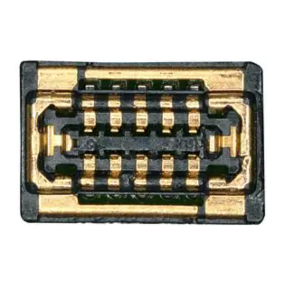
MULTI RF BOARD TO FPC CONNECTOR
BM56G Series Guideline
Approver
Checker
Designer
Checker
BM56G Series Guideline
Pitch:0.35mm, Width:2.2mm
Stacking height:0.6mm
WR.FUKUCHI
TY.OOI
KT.KUSAKA
Approver
ETAD-H1035-00
1
13
PAGE:
OF
20220121
20220121
20220120
RevNo
0
DATE
Advertisement
Table of Contents

Related Manuals for Hirose BM56G Series


Summary of Contents for Hirose BM56G Series
- Page 1 TITLE BM56G Series Guideline ETAD-H1035-00 PRODUCT MULTI RF BOARD TO FPC CONNECTOR PAGE: Pitch:0.35mm, Width:2.2mm HIROSE ELECTRIC CO.,LTD. Stacking height:0.6mm BM56G Series Guideline Approver WR.FUKUCHI 20220121 Checker TY.OOI 20220121 Designer KT.KUSAKA 20220120 REVISIONS RevNo Designer Checker Approver DATE...
-
Page 2: Table Of Contents
TITLE BM56G Series Guideline ETAD-H1035-00 PRODUCT MULTI RF BOARD TO FPC CONNECTOR PAGE: Pitch:0.35mm, Width:2.2mm HIROSE ELECTRIC CO.,LTD. Stacking height:0.6mm Table of contents Notice for Device Handling ................................ 3 1.1 Notice for mechanical designing ............................... 3 1.2 FPC fixing ....................................3 1.3 Allocation of other components around connector ........................ -
Page 3: Notice For Device Handling
TITLE BM56G Series Guideline ETAD-H1035-00 PRODUCT MULTI RF BOARD TO FPC CONNECTOR Pitch:0.35mm, Width:2.2mm PAGE: HIROSE ELECTRIC CO.,LTD. Stacking height:0.6mm Notice for Device Handling 1.1 Notice for mechanical designing There is still possibility that connectors are disengaged if strong impact, such as dropping, is put against connectors in use. -
Page 4: Allocation Of Other Components Around Connector
TITLE BM56G Series Guideline ETAD-H1035-00 PRODUCT MULTI RF BOARD TO FPC CONNECTOR Pitch:0.35mm, Width:2.2mm PAGE: HIROSE ELECTRIC CO.,LTD. Stacking height:0.6mm 1.3 Allocation of other components around connector Please do not locate any material which may effect on connector mating around the connectors. -
Page 5: Notice For Pwb Designing
TITLE BM56G Series Guideline ETAD-H1035-00 PRODUCT MULTI RF BOARD TO FPC CONNECTOR Pitch:0.35mm, Width:2.2mm PAGE: HIROSE ELECTRIC CO.,LTD. Stacking height:0.6mm Notice for PWB designing 2.1 Recommended PWB pattern and connector location For the recommended PWB pattern, please see the product drawing. - Page 6 TITLE BM56G Series Guideline ETAD-H1035-00 PRODUCT MULTI RF BOARD TO FPC CONNECTOR Pitch:0.35mm, Width:2.2mm PAGE: HIROSE ELECTRIC CO.,LTD. Stacking height:0.6mm Pad layout and shield position for plug (E-E),E’ E’ Pad layout and contact position for plug (F-F),F’ F’ Pad layout and shield position for plug (G-G),G’...
-
Page 7: Pwb Designing
TITLE BM56G Series Guideline ETAD-H1035-00 PRODUCT MULTI RF BOARD TO FPC CONNECTOR Pitch:0.35mm, Width:2.2mm PAGE: HIROSE ELECTRIC CO.,LTD. Stacking height:0.6mm 2.2 PWB designing -Please design PWB layout properly so that front fillet, back fillet and side fillet are formed. The recommended PWB layout is designed so that the connector can be soldered to the PWB appropriately. -
Page 8: Notice For Mounting
TITLE BM56G Series Guideline ETAD-H1035-00 PRODUCT MULTI RF BOARD TO FPC CONNECTOR Pitch:0.35mm, Width:2.2mm PAGE: HIROSE ELECTRIC CO.,LTD. Stacking height:0.6mm Notice for Mounting 3.1 Metal mask design For the recommended metal mask design, please see the product drawing. 3.2 Fillet forming... -
Page 9: Notice For Connector Handling
TITLE BM56G Series Guideline ETAD-H1035-00 PRODUCT MULTI RF BOARD TO FPC CONNECTOR Pitch:0.35mm, Width:2.2mm PAGE: HIROSE ELECTRIC CO.,LTD. Stacking height:0.6mm Notice for Connector Handling 4.1 Connector insertion operation Please mate this connector by hands. Manual for inserting operation Find the alignment area with hand to locate the connector in the appropriate mating position. This connector has alignment chamber (guidance ribs) on receptacle side and R on plug side, so that the connector can be self-aligned. -
Page 10: Connector Withdrawal Operation
TITLE BM56G Series Guideline ETAD-H1035-00 PRODUCT MULTI RF BOARD TO FPC CONNECTOR Pitch:0.35mm, Width:2.2mm PAGE: HIROSE ELECTRIC CO.,LTD. Stacking height:0.6mm 4.2 Connector withdrawal operation 1) It is desirable to withdraw the connector in the vertical direction against mating direction. However, in the case connector has high pin counts or thinner FPC and stiffener, it makes more difficult to withdraw the connector in the vertical direction. -
Page 11: Rf Evaluation Board Design Information
Please use the thickness’ information of the each layers as a reference, and please modify/control the impedance of this product at 50Ω±10%. Recommendation for the coaxial connector part is a Hirose’s product: HK-LR-SR2 (K connector: 2.92mm). Please optimize the BM56 and the coaxial (HK-LR SR2) part by cutting out the L2 layer. - Page 12 TITLE BM56G Series Guideline ETAD-H1035-00 PRODUCT MULTI RF BOARD TO FPC CONNECTOR Pitch:0.35mm, Width:2.2mm PAGE: HIROSE ELECTRIC CO.,LTD. Stacking height:0.6mm Receptacle RF Evaluation Board: Example of the cutout dimension Pin Assignment: Ex. S:RF Signal Example of Cutout Dimension(mm) G:GND Plug RF Evaluation Board: Example of the cutout dimension Pin Assignment: Ex.
-
Page 13: Additional Information
TITLE BM56G Series Guideline ETAD-H1035-00 PRODUCT MULTI RF BOARD TO FPC CONNECTOR Pitch:0.35mm, Width:2.2mm PAGE: HIROSE ELECTRIC CO.,LTD. Stacking height:0.6mm Additional information 6.1 PWB cleaning Do not wash the board because it may be cause malfunction of the connector. 6.2 PWB handling In the operation which could give stress to the mounted connector, including cutting or bending PWB, keep soldering area from mechanical stress.
Need help?
Do you have a question about the BM56G Series and is the answer not in the manual?
Questions and answers