
Related Manuals for STAMOS soldering S-LS-1


Summary of Contents for STAMOS soldering S-LS-1
- Page 1 S-LS-1 BEDIENUNGSANLEITUNG User manual | Manuel d´utilisation | Istruzioni per l‘uso | Manual de instrucciones...
- Page 2 INHALT | CONTENT | CONTENU | CONTENIDO | TREŚĆ...
- Page 3 SICHERHEITSHINWEISE Allgemeine Sicherheitshinweise bei der Benutzung von Elektrogeräten: Um das Verletzungsrisiko durch Feuer oder Stromschlag zu minimieren, bitten wir Sie stets einige grundlegende Sicherheitsvorkehrungen zu treffen, wenn Sie dieses Gerät verwenden. Bitte lesen Sie diese Bedienungsanleitung sorgfältig und vergewissern Sie sich, dass keine Fragen offen bleiben. Bewahren Sie diese Betriebsanleitung bitte sorgfältig in der Nähe des Produktes auf, um bei Fragen auch später noch einmal nachschlagen zu können.
- Page 4 VERWENDUNGSBEREICH Das Gerät ist vorgesehen für: Löten oder Entlöten elektronischer Elemente wie beispielsweise: SOIC, CHIP, QFP, PLCC, BGA, SMD uvm. Schrumpfen, Trocknen von Farbe, Entfernen von Klebstoffen, Abtauen, Wärmedämmung, Kunststoffschweißen. DC-Netzteil bei der Durchführung wissenschaftlicher Untersuchungen, Produktentwicklung, Laborarbeiten etc. Für alle Schäden bei nicht bestimmungsgemäßer Verwendung haftet allein der Betreiber. WIE FUNKTIONIERT DAS GERÄT –...
- Page 5 VOR DER ERSTEN BENUTZUNG Prüfung nach Erhalt der Ware Bei Erhalt der Ware, prüfen Sie die Verpackung auf Unversehrtheit und öffnen Sie diese. Wenn die Verpackung Beschädigungen aufweist, so setzen Sie sich innerhalb von 3 Tagen in Verbindung mit der Transportgesellschaft und Ihrem Vertriebspartner, und dokumentieren so gut wie möglich die Beschädigungen.
- Page 6 Wenn das Display „---” anzeigt bedeutet dies, dass die Ausgangstemperatur unter 100 ⁰C liegt und die Heißluft- ALLGEMEINE ANMERKUNGEN Entlötstation sich im Modus „STAND BY” befindet. Der Heißluft-Entlöter befindet sich in der Halterung. Wenn das Display „S-E”, bedeutet dies, dass der Lötkolben nicht angeschlossen ist; es kann sein, dass bei der Heißluft-Entlötstation ein Problem mit dem Sensor vorliegt.
- Page 7 Vor Auswechseln des Heizelementes muss überprüft werden, dass die Heißluft-Entlötstation vollkommen abgekühlt ist. Die Schrauben von der Abdeckung des Kolbens entfernen. Den Griff (2) lösen die Umfassung des Lötkolbens abnehmen. Den Ventilator vorsichtig herausnehmen und die Schrauben, welche die Platte mit den Leitungen verbindet, vorsichtig herausdrehen.
-
Page 9: Soldering Station
CAUTIONS General safety information for the use of electrical devices: To avoid injury from fire or electric shock, please ensure compliance with safety instructions when using this device. Please read the instruction carefully and make sure that you have understood it well. Keep the manual near the equipment to be able to read it at any time. -
Page 10: Principle Of Operation
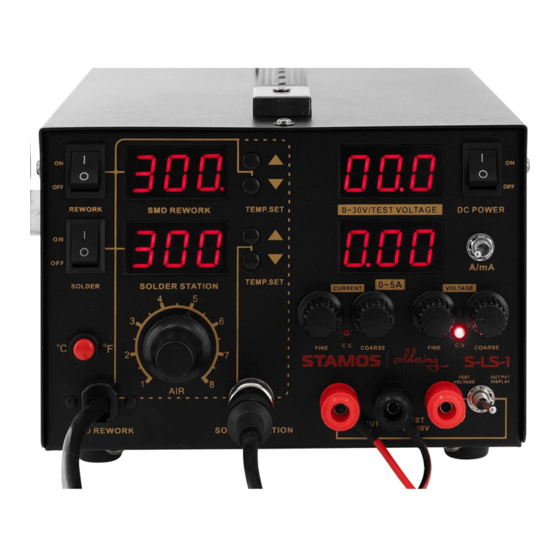
Any damage resulting from a non-conform use of the device is payable by the user! PRINCIPLE OF OPERATION Assembly: HOT AIR temperature set buttons switch between output / input voltage HOT AIR temperature display output current fine adjustment knob HOT AIR turn on / off switch current stabilization indicator soldering iron turn on / off switch output voltage fine adjustment knob... - Page 11 SMD REWORK STATION Device must be placed on stable work table, HOT AIR gun must be placed into the holder. Fix the appropriate nozzle and connect the device to the power source. Turn on the device with the main switch placed at the back of the device, turn on the HOT AIR gun with switch (3), gun will start to heat.
- Page 12 SAFETY ISSUES REMARKS Nozzles should be installed without the use of excessive force, also do not use the pliers or tweezers. Do not over tighten the mounting screws of the nozzle. Tips and nozzles can be changed when the HOT AIR gun and the soldering iron are completely cold. It is forbidden to use the device near the flammable or combustible elements and objects or at similar places.
-
Page 13: Regular Cleaning
REPLACEMENT OF THE SOLDERING IRON TIP AND SOLDERING IRON HEATING CORE ELE- MENT nut for mounting the soldering iron tip housing soldering iron tip housing soldering iron tip plastic nut for mounting the heater and the board wires spring heater wires board handle Before heater replacement make sure that the soldering iron is completely cold. - Page 15 ZALECENIA ODNOŚNIE BEZPIECZEŃSTWA Ogólne zalecenia odnośnie bezpieczeństwa podczas użytkowania urządzeń elektrycznych: W celu zminimalizowania ryzyka obrażeń na skutek działania ognia lub porażenia prądem prosimy Państwa o stałe prze- strzeganie kilku podstawowych zasad bezpieczeństwa podczas użytkowania urządzenia. Prosimy o staranne przeczytanie niniejszej instrukcji użytkowania i upewnienie się, że znaleźli Państwo odpowiedzi na wszystkie pytania dotyczące tego urządzenia.
-
Page 16: Przed Pierwszym Użyciem
OBSZAR ZASTOSOWANIA Urządzenie przeznaczone jest do: Różnego rodzaju lutowania lub rozlutowywania elementów elektronicznych, takie jak: SOIC, CHIP, QFP, PLCC, BGA, SMD, itp. Obkurczania, suszenia farb, usuwania klejów, rozmrażania, ocieplania, spawania tworzyw sztucznych. Zasilania DC w zakresie wykonywania badań naukowych, rozwoju produktu, laboratorium, itp. Odpowiedzialność... -
Page 17: Montaż Urządzenia
Utylizacja opakowania Prosimy o zachowanie elementów opakowania (tektury, plastykowych taśm oraz styropianu), aby w razie konieczności od- dania urządzenia do serwisu można go było jak najlepiej ochronić na czas przesyłki! MONTAŻ URZĄDZENIA Umiejscowienie urządzenia Urządzenie powinno się ustawić na powierzchni roboczej, która pod względem wymiarów będzie co najmniej odpowiadała wymiarom urządzenia. - Page 18 W przypadku gdy wyświetlacz pokazuje „F-2” oznacza to, że wentylator jest zablokowany. W momencie włączania urządzenia obie kolby muszą znajdować się w odpowiednich uchwytach. Należy upewnić się, że wylot kolby hot air jest czysty i nie zawiera żadnych blokad ani przeszkód. Nodczas korzystania z małych dysz należy pamiętać...
- Page 19 WYMIANA ELEMENTU GRZEWCZEGO ORAZ KOŃCÓWKI KOLBY LUTOWNICZEJ nakrętka mocująca obudowę końcówki lutowniczej obudowa końcówki lutowniczej końcówka lutownicza nakrętka mocująca grzałkę wraz z płytką z przewodami sprężyna grzałka płytka z przewodami uchwyt Przed wymianą końcówki lutowniczej oraz elementu grzewczego należy się upewnić, że kolba lutownicza jest całkowicie zimna.
-
Page 21: Norme Di Sicurezza
NORME DI SICUREZZA Norme di sicurezza generali per l`utilizzo di molti apparecchi elettrici: Per minimizzare il rischio di ferite provocate da scottature o bruciature e da un riscaldamento eccessivo dell`apparecchio si prega di osservare attentamente e rispettare le norme e procedure di sicurezza, prima di utilizzare l`apparecchio. Legge- re attentamente le istruzioni d`uso. -
Page 22: Campo Di Applicazione
CAMPO DI APPLICAZIONE Il dispositivo è realizzato per: Saldare o dissaldare elementi elettronici come ad esempio: SOIC, CHIP, QFP, PLCC, BGA, SMD e molto altro Riduzione,asciugatura colore, rimozione di collanti, sbrinamento, riduzione calore, saldatura di materiali plastici. Corrente DC per svolgere analisi scientifiche, sviluppo di prodotti, operazioni svolte in laboratori ecc., Laborarbei- ten etc. - Page 23 MONTAGGIO DEL DISPOSITIVO Posizionamento del dispositivo Il dispositivo deve essere posizionato su un piano di lavoro conforme con le dimensioni del dispositivo. Per garantire un uti- lizzo ottimale dell´apparecchio, Il piano di lavoro deve essere perfettamente in piano, risultare asciutto e resistente al calore, nonché...
-
Page 24: Istruzioni Sulla Sicurezza
Quando il display mostra la scritta „F-2”, vuol dire che il ventilatore si è bloccato. All’accensione dell’apparecchio è necessario che entrambi i saldatoi si trovino sui relativi supporti. Occorre assicurarsi che la punta della stazione dissaldante ad aria calda sia pulita e non siano presenti ostacoli o ostruzioni. - Page 25 S OSTITUZIONE DEGLI ELEMENTI RISCALDANTI E DELLA PUNTA DEL SALDATOIO Dado per il fissaggio della punta del saldatoio Elemento riscaldante Alloggiamento della punta Piastra con fili Punta del saldatoio Impugnatura Dado con cavo piastra scaldante Molla Prima di procedere alla sostituzione della punta del saldatore e dell’elemento riscaldante, attendere che il saldatore sia completamente raffreddato.
-
Page 27: Medidas De Seguridad
MEDIDAS DE SEGURIDAD Instrucciones generales sobre seguridad en el uso de dispositivos eléctricos: Para reducir el riesgo de lesiones por quemadura o electrocución, le rogamos que tenga en cuenta ciertas instrucciones de seguridad cuando utilice este aparato. Lea detenidamente el manual de instrucciones de este dispositivo y asegúrese de entender todas las consignas de seguridad. -
Page 28: Campo De Aplicación
CAMPO DE APLICACIÓN El equipo ha sido diseñado para: Soldar y desoldar elementos electrónicos como: SOIC, CHIP, QFP, PLCC, BGA, SMD, etc. Contraído, secado de pintura, eliminado de pegamento, descongelado, aislamiento térmico, soldadura de plástico. Para trabajos científicos de investigación, desarrollo de productos, trabajos de laboratorio, etc. El usuario es responsable de los daños derivados de un uso inadecuado de la máquina. -
Page 29: Montaje De La Máquina
MONTAJE DE LA MÁQUINA Colocación del equipo El equipo se debe instalar en una superficie de trabajo que tenga por lo menos las mismas dimensiones que el dispositivo. La superficie de trabajo debe ser plana, seca y tener una altura que permita trabajar cómodamente. Asimismo, asegúrese que la ésta sea resistente al calor. - Page 30 Si el display muestra „F2”, significa que el ventilador está bloqueado. Al encender el equipo, tanto el cautín como la pistola de aire caliente tienen que estar situados en los soportes cor- respondientes. Asegúrese que las ranuras de ventilación del dispositivo estén limpias y sin objetos que las bloqueen. Cuando utilice boquillas pequeñas, asegúrese que el flujo de aire es acorde con la dimensión de las mismas, para evitar que la unidad de aire caliente resulte dañada, debido a un excesivo caudal a tan alta temperatura.
- Page 31 SUSTITUCIÓN DE LA RESISTENCIA Y DE LA PUNTA DEL CAUTÍN Tuerca para la fijación de la punta Muelle Cubierta de la punta Resistencia Punta de soldadura Placa con alambres Tuerca con cable a la placa calefactora Mango Antes de proceder con el cambio de la punta de soldadura o de la resistencia, espere a que el cautín se enfríe. Cambio de la punta de soldadura: Desenrosque la tuerca que fija el tapón de la punta y retírelo.
-
Page 33: Consignes De Sécurité
CONSIGNES DE SÉCURITÉ Consignes de sécurité générales pour de l‘utilisation des appareils électriques: Afin de diminuer les risques de brûlures, d‘incendie ou d‘électrocution, veuillez observer constamment ces quelques consignes de sécurité de base lors de l‘utilisation de l‘appareil. Veuillez lire soigneusement ces instructions d‘emploi et assurez-vous que vous avez trouvé... -
Page 34: Domaine D'utilisation
DOMAINE D’UTILISATION L’appareil est prévu pour: Souder et dessouder des éléments électroniques tels que les SOIC, CHIP, QFP, PLCC, BGA, SMD, etc. Rétrécir, sécher de la peinture, enlever des adhésifs, dégivrer, isoler, souder des matières plastiques. Le bloc d’alimentation C.C. permet d’effectuer des recherches scientifiques, développer des produits, effectuer tra- vaux de laboratoires etc. -
Page 35: Avant La Première Utilisation
AVANT LA PREMIÈRE UTILISATION Vérification dès réception de l’appareil Dès réception de la marchandise, vérifiez l‘état et l‘intégrité de l‘emballage puis ouvrez-le. Dans le cas où le colis semble endommagé, veuillez prendre contact avec la société de transport et la société de vente dans les 3 jours en donnant en maximum d‘informations et/ou de photos afin de décrire au mieux les dommages constatés. -
Page 36: Remarques Générales
REMARQUES GÉNÉRALES Lorsque l’écran affiche „---”, cela signifie que la température de sortie se situe en-dessous de 100°C et que la stati- on de dessoudage à air chaud se trouve en mode « Veille ». La buse à air chaud doit être placée sur son support. Lorsque l’écran affiche „S-E”, cela signifie que la buse n’est pas branchée à... -
Page 37: Nettoyage Courant
Avant de remplacer l‘élément chauffant, vérifiez que le poste à dessouder à air chaud ait complétement refroidi. Retirez les vis du couvercle du fer. Retirez la poignée (2) pour desserrer le caisson du fer à souder. Retirez prudemment le ventilateur et dévissez les boulons reliant la plaque avec les conduits. Retirez l‘élément chauffant de la plaque (faites attention aux raccords des câbles) Retirez l‘élément de chauffage du caisson en veillant à... -
Page 39: Bezpečnostní Pokyny
BEZPEČNOSTNÍ POKYNY Obecné bezpečnostní pokyny při používání elektrických zařízení: Aby se minimalizovalo riziko zranění v důsledku požáru nebo úrazu elektrickým proudem, dodržujte základní bezpečnostní principy při používání zařízení. Přečtete si pečlivé tento návod a ujistěte se, že jste si našli odpovědi na všechny Vaše otázky týkající... -
Page 40: Oblast Použití
OBLAST POUŽITÍ Zařízení je určeno pro: Různého typu pájení nebo rozpájení elektronických prvků jako jsou: SOIC, CHIP, QFP, PLCC, BGA, SMD apod. Smršťování, sušení barev, odstraňování lepidel, rozmrazování, zateplení, svařování plastu. Napájení DC při provádění vědeckých výzkumů, vývoje výrobku, v laboratoři apod. Odpovědnost za veškeré... -
Page 41: Obecné Poznámky
MONTÁŽ ZAŘÍZENÍ Umístění zařízení Zařízení by mělo být umístěno na provozní ploše, jíž rozměry odpovídají rozměrům zařízení. Za účelem umožnit optimální provoz zařízení, by měla být provozní plocha rovná, suchá, na odpovídající výšce a odolná vůči teplu. Pamatujte, aby napájení zařízení odpovídalo údajům na typovém štítku! OVLÁDÁNÍ... -
Page 42: Bezpečnostní Informace
Ujistěte se, že výstup páječky hot air je čistý a nemá žádné blokády či překážky. Při používání malých trysek si pamatujte, že musí být průtok vzduchu přizpůsoben konkretní trysce a aby se zabránilo poškození páječky hot air neudržujte vysoký průtok vzduchu spolu s vysokou teplotou příliš dlouho. V závislosti na požadavcích uživatele mohou různá... - Page 43 VÝMĚNA OHŘÍVAČE A HROTU PÁJEČKY upevňovací matice krytu pájecího hrotu kryt pájecího hrotu pájecí hrot upevňovací matice ohřívače s deskou s kabely pružina ohřívač deska s kabely držák Před výměnou pájecího hrotu a ohřívače se ujistěte, že je páječka zcela chladná. VÝMĚNA PÁJECÍHO HROTU: Odšroubujte upevňovací...
- Page 47 Hiermit bestätigen wir, dass die hier in dieser Anleitung aufgeführten Geräte Ce-konform sind. We hereby certify that the appliances listed in this manual are Ce compliant. Par la présente, nous confirmons que les appareils présentés dans ce mode d´emploi sont conformes aux normes Ce. Niniejszym potwierdzamy, że urządzenia opisane w tej instrukcji są...
- Page 48 Umwelt- und Entsorgungshinweise Hersteller an Verbraucher Sehr geehrte Damen und Herren, gebrauchte Elektro- und Elektronikgeräte dürfen gemäß europäischer Vorgaben [1] nicht zum unsortierten Siedlungsabfall gegeben werden, sondern müssen getrennt erfasst werden. Das Symbol der Abfalltonne auf Rädern weist auf die Notwendigkeit der getrennten Sammlung hin.
Need help?
Do you have a question about the soldering S-LS-1 and is the answer not in the manual?
Questions and answers