Table of Contents
Advertisement
Quick Links
D350-M1
Model:
Grid Support Utility Interactive Inverter
16 ~ 60 V d.c.
Range of Input Operating Voltage
Range of Peak Power MPPT Voltage
33 ~ 48 V d.c.
Start-up Voltage
22 V d.c.
Max Input Current
11.5 A d.c.
Max Input Short Circuit Current
15.0 A d.c.
240 V a.c.
Nominal Output Voltage
Max Continuous Output Current
1.52 A a.c.
Nominal Output Frequency
60 Hz
Max Continuous Output Power
349 VA
Output Power Factor Rating
> 0.99 (Default)
Peak Conversion Efficiency
96.7 %
Type of Enclosure
Type 6
Operating Ambient Temp
-40 to +65
UL1741 CSA C22.2No.107.1-16
Made in China
Power Center+
D700-M2
Model:
Grid Support Utility Interactive Inverter
Range of Input Operating Voltage
16 ~ 60 V d.c.
33 ~ 48 V d.c.
Range of Peak Power MPPT Voltage
Start-up Voltage
22 V d.c.
Max Input Current
(2x) 11.5 A d.c.
Max Input Short Circuit Current
(2x) 15.0 A d.c.
Nominal Output Voltage
240 V a.c.
Max Continuous Output Current
2.92 A a.c.
Nominal Output Frequency
60 Hz
Max Continuous Output Power
696 VA
Output Power Factor Rating
> 0.99 (Default)
Peak Conversion Efficiency
96.7 %
Type of Enclosure
Type 6
Operating Ambient Temp
-40 to +65
UL1741 CSA C22.2No.107.1-16
Made in China
Power Center+
D1500-M4
Model:
Grid Support Utility Interactive Inverter
Range of Input Operating Voltage
16 ~ 60 V d.c.
Range of Peak Power MPPT Voltage
33 ~ 48 V d.c.
Start-up Voltage
22 V d.c.
Max Input Current
(4x) 11.5 A d.c.
Max Input Short Circuit Current
(4x) 15.0 A d.c.
Nominal Output Voltage
240 V a.c.
Max Continuous Output Current
5.99 A a.c.
Nominal Output Frequency
60 Hz
Max Continuous Output Power
1438 VA
Output Power Factor Rating
> 0.99 (Default)
Peak Conversion Efficiency
96.7 %
Type of Enclosure
Type 6
Operating Ambient Temp
-40 to +65
UL1741 CSA C22.2No.107.1-16
Made in China
Power Center+
Installation Manual
CAUTION: Risk of electric shock – Do not remove cover.
No user serviceable parts inside. Refer servicing to
qualified service personnel. Both ac and dc voltage sources
are terminated inside this equipment. Each circuit must be
individually disconnected before servicing. When the photovoltaic
array is exposed to light, it supplies a dc voltage to this equipment.
ATTENTION: Risque de choc électrique – ne pas enlever le couvercle.
Aucune pièce interne réparable par l'utilisateur. Toute réparation
doit être uniquement confiée à du personnel qualifié. A l'intérieur de
l'onduleur on retrouve 2 tensions AC et DC. Chaque circuit doit être
déconnecté individuellement avant chaque entretien. Lorsque le
panneau photovoltaïque est exposé à la lumière, il fournit une
tension DC à cet appareil.
CAUTION: Hot surfaces – To reduce the risk of burns – Do
not touch. ATTENTION: Les surfaces chaudes – pour
réduire le risque de brûlure – Ne pas toucher.
This device complies with part 15 of the FCC
Rules. Operation is subject to the following
two conditions: (1) This device may not cause
C
US
harmful interference, and (2) this device must accept
261002
any interference received, including interference that
may cause undesired operation.
www.duracellpowercenter.com
Duracell is a registered trademark of Duracell U.S.
Operations, Inc., used under license. All rights reserved.
Advertisement
Table of Contents
Troubleshooting

Subscribe to Our Youtube Channel
Related Manuals for Duracell D350-M1


Summary of Contents for Duracell D350-M1
- Page 1 (2) this device must accept 261002 any interference received, including interference that may cause undesired operation. www.duracellpowercenter.com Duracell is a registered trademark of Duracell U.S. Operations, Inc., used under license. All rights reserved. D700-M2 Model: Grid Support Utility Interactive Inverter CAUTION: Risk of electric shock –...
- Page 2 flexibility and reliability of the system. About the Manual This manual contains important instructions for the D350-M1 / D700-M2 / D1500-M4 microinverters. It must be read in its entirety before installing or commissioning the equipment. For safety, only qualified technicians, who have received training or have demonstrated skills can install and maintain this microinverter under the guide of this document.
-
Page 3: Table Of Contents
6.1 Setting up the monitoring system ......................12 7 Troubleshooting ............................13 7.1 Troubleshooting List: all models ......................13 7.2 Troubleshooting List: D350-M1 / D700-M2 ................... 13 7.3 Troubleshooting List: D1500-M4 ......................14 7.4 Status LED Indicator ..........................15 7.4.1 Start-up Modes ........................... 15 7.4.2 Run Modes ............................ -
Page 4: Important Notes
This manual describes the assembly, installation, commissioning, and maintenance of the following models of Power Center+ microinverters: D350-M1 / D700-M2 / D1500-M4 1.2 Target Group This manual is only for qualified technicians, who have been trained or have demonstrated skills to install and maintain this microinverter under the guide of this document for safety purposes. -
Page 5: Explanation Of Symbols
Installation Manual 2.2 Explanation of Symbols Symbol Usage Treatment To comply with the European Directive 2002/96/EC on waste Electrical and Electronic Equipment and its implementation as national law, electrical equipment that has reached the end of its life must be collected separately and returned to an approved recycling facility. -
Page 6: Product Introduction
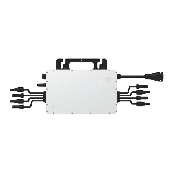
Static MPPT efficiency 99.80%; Dynamic MPPT efficiency 99.76% in overcast weather. Power factor (adjustable) 0.8 leading……0.8 lagging. External antenna for stronger communication with the DTU. High reliability: NEMA6 (IP67) enclosure; 6000V surge protection. 3.1.1 D350-M1: Terminals / Dimensions A – DC connector B – Antenna C – AC connector 3.1.2 D700-M2: Terminals / Dimensions... -
Page 7: D1500-M4: Terminals / Dimensions
Installation Manual 3.1.3 D1500-M4: Terminals / Dimensions A – Antenna B – DC connectors C – AC connector 4 Modes of Operation Normal: Under this mode, the microinverter is operating normally and converts DC power into AC power to support the house loads and feed into the grid. -
Page 8: Installation Planning
Installation Manual 5 Installation Planning... -
Page 9: Installation Precautions
DC short circuit current. The output DC power of PV module is NOT recommended to exceed 1.35 times the output AC power of the microinverter. Refer to Warranty Terms & Conditions for more information. D1500-M4 D350-M1 D700-M2... -
Page 10: Space Distance Required
Under such installation conditions, it is better for the microinverters to be installed 50cm above the roof. Otherwise, additional DTUs (large arrays) may be required to ensure the communication quality between the DTUs and the microinverters. Residential rooftop installations with metal roofs may require the DTU to be installed closer to the PV array. D350-M1 D700-M2 D1500-M4... -
Page 11: Preparation
Avoid electromagnetic interference that can compromise the correct operation of electronic equipment. When choosing the position of installation, comply with the following conditions: Install only on structures specifically conceived for photovoltaic modules. Install the microinverter underneath a photovoltaic module to shade it from direct sunlight. D1500-M4 D350-M1 D700-M2... -
Page 12: Pre-Installation: Ac Trunk Cable End Cap Installation
Installation Manual 5.5 Pre-Installation: AC trunk cable end cap installation From the open end of the trunk cable reel, replace the cable end with an end cap at the bus connector. Use the bus connector unlock tool to unlock the port upper cover. Loosen the three screws with the screwdriver. -
Page 13: Installation: Mounting The Microinverter
Installation Manual Note: Refer to Appendix B (split-phase 120/240) or Appendix C (three phase 120/208) at the end of this manual for the following instruction: Terminate the loose end of the trunk cable in an AC junction box rated for use and installed as per the local electrical code. -
Page 14: Installation: Connecting The Ac Trunk Cable To The Microinverters
Installation Manual 5.8 Installation: Connecting the AC trunk cable to the microinverters Attach the AC bus cable with the mounting rail, and fix the cable with tie wraps. Push the AC connector of the microinverter to the trunk cable bus connector until you hear “click”. Plug unused AC connetors with the AC sub cap on the vacant plug to ensure waterproof and dustproof. -
Page 15: Installation: Pv Input Port Connections
Installation Manual 5.10 Installation: PV input port connections Connect the DC cables from the PV module(s)to the PV input port(s) of the microinverter. D350-M1 D700-M2 D1500-M4 6 Energizing the system Turn on the AC breaker of the branch circuit. Turn on the main AC breaker of the house. Your system will start to generate power after the regulated grid timing sequence has completed. -
Page 16: Troubleshooting
Installation Manual 7 Troubleshooting 7.1 Troubleshooting List: all models Alarm Title Suggestion Code Over temperature Check the ventilation and ambient temperature at the microinverter. Correct as required. protection Grid config parameter Check if the grid configuration parameter is correct and upgrade again. error If the alarm occurs accidentally and the microinverter can still work normally, no special SW code 126... -
Page 17: Troubleshooting List: D350-M1 / D700-M2
Installation Manual 7.2 Troubleshooting List: D350-M1 / D700-M2 Alarm Title Suggestion Code Port 1 over voltage Ensure that the PV module open-circuit voltage is less than or equal to the maximum (D700-M2 only) input voltage. Port 2 over voltage Port 1... -
Page 18: Status Led Indicator
Installation Manual 7.4 Status LED Indicator The LED flashes five times at start up. All green flashes (1s gap) indicate normal start up. 7.4.1 Start-up Modes Flashing green five times (0.3s gap): Start-up success Flashing Red five times (0.3s gap): Start-up failure 7.4.2 Run Modes Flashing Fast Green (1s gap): Producing power. -
Page 19: Removing A Microinverter
Installation Manual 7.6 Removing a microinverter De-energize the AC branch circuit breaker. Remove the PV panel that is covering the microinverter from the racking, and cover the panel(s) that connect to the PV input(s). Use a DC rated clamp meter to measure and make sure there is no current flowing in the DC wires between the panel(s) and the microinverter. -
Page 20: Disposal
Installation Manual 8.2 Disposal If the equipment is not used immediately or is stored for long periods, check that it is correctly packed. The equipment must be stored in well-ventilated indoor areas that do not have characteristics that might damage the components of the equipment. -
Page 21: 10Technical Data
Installation Manual 10 Technical Data Model D350-M1 D700-M2 D1500-M4 DC input ports Number of PV input ports Maximum module power, per port (Wdc) Peak power MPPT voltage range (Vdc) 33~48 33~48 36~48 Start-up voltage (Vdc) Operating voltage range (Vdc) 16~60 Maximum input voltage (Vdc) Max. -
Page 22: Grid Support Details
Installation Manual 11 Grid Support Details The D350-M1 / D700-M2 / D1500-M4 microinverter is a grid support utility interactive Manufacturer stated accuracy inverter. The microinverters comply with California Rule 21. The grid support functions are Measurement Accuracy controlled via the Power Center+ Monitoring Platform. The PC-PRO is required in this PV system. -
Page 23: Sa11: Ramp Rate (Rr) And Soft Start (Ss)
SA12: Specified Power Factor (SPF) Adjustment Range -0.8 -1.0 Inductive, under excited, power factor Capacitive, overexcited, power factor SA13: Volt/VAr (VV) Units D350-M1 D700-M2 D1500-M4 Output power rating 1438 Reactive power absorption (inductive, under excited) Reactive power production (capacitive, overexcited) -
Page 24: Appendix A: Installation Map Template
Installation Manual Appendix A: Installation Map Template... -
Page 25: Appendix B: 120/240 Split-Phase Electrical Single Line Diagram
Installation Manual Appendix B: 120/240 Split-phase Electrical Single Line Diagram... -
Page 26: Appendix C: 120/208 Three-Phase Electrical Single Line Diagram
Installation Manual Appendix C: 120/208 Three-phase Electrical Single Diagram... -
Page 27: Appendix D: Ac Branch Limit Calculator
The following table highlights various combinations of quad, dual, and single microinverters that can be connected to a single 10 AWG trunk cable as a single AC branch with a 30 Amp circuit protection rating. Not all possible combinations are shown. 240V D1500-M4 (Quad) D700-M2 (Dual) D350-M1 (Single) 208V D1500-M4 (Quad) D700-M2 (Dual) D350-M1 (Single) - Page 28 Installation Manual Doc-97010...
Need help?
Do you have a question about the D350-M1 and is the answer not in the manual?
Questions and answers