Table of Contents
Advertisement
Advertisement
Table of Contents

Related Manuals for Duracell Dura-i


Summary of Contents for Duracell Dura-i
- Page 1 Dura-i Single Phase ESS Inverter Operation Manual...
- Page 2 Duracell is a registered trademark of Duracell Batteries BV and Duracell U.S. Operations, Inc., used under license. All rights reserved. Manufactured under license and warranty supported by Puredrive Energy Limited in Toddington,UK. NOTE: NEITHER DURACELL BATTERIES BV, DURACELL U.S. OPERATIONS, INC., NOR ITS AFFILIATES ARE INVOLVED IN THE DESIGN, MANUFACTURE, MARKETING OR DISTRIBUTION OF THE PRODUCTS AND THEY DO NOT MAKE ANY (AND HEREBY DISCLAIM ALL) EXPRESS OR IMPLIED WARRANTIES RELATING TO THE PRODUCTS.
-
Page 3: About This Manual
Calls attention to important information, best practices and tips: NOTE supplemental additional safety instructions for your better use of the ESS inverter and to reduce the waste of resources. Dura-i Inverter Operation Manual... -
Page 4: Table Of Contents
4.3.1. NTC connection for lead-acid battery 4.4. PV Connection (N/A for AC Couple Inverter) 4.5. Meter/CT Connection 4.5.1. Meter Connection 4.5.2. CT Connection 4.6. Communication Connection 4.6.1. BMS Connection (Only for Lithium Battery) 4.6.2. DRMs Connection Dura-i Inverter Operation Manual... - Page 5 Shutdown Procedure Commissioning ..........................6.1. Inspection 6.2. Commissioning Procedure User Interface ..........................7.1. LED/LCD 7.1.1. LED Introduction 7.2. Dura-i App Setting Guide 7.2.1. Download the APP 7.2.2. App Architecture 7.2.3. Local Login Maintenance ..........................8.1. Routine Maintenance 8.2. Inverter Troubleshooting 8.3.
-
Page 6: Safety
Do not disconnect under load, otherwise there will be a danger of fi re. under load! Environmental Protection Use Period. Refer to the operating instructions. Don’t dispose of the inverter with household waste. Grounding terminal. General Safety Symbols Dura-i Inverter Operation Manual... -
Page 7: Safety Precautions
Don’t connect ESS inverter in the following ways: The BACKUP Port should not be connected to the grid; A single PV panel string should not be connected to two or more inverters. Safety Precautions Dura-i Inverter Operation Manual... -
Page 8: Product Introduction
It can provide power for emergency use during the grid power outage by using energy from a battery. Grid Sensor Inverter Inverter Normal Load Cloud Monitoring Device Critical Load Battery Figure 2. AC Couple Inverter Application System Overview Dura-i Inverter Operation Manual... -
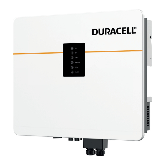
Page 9: Product Appearance
Battery Connect Terminals PV Switch PV Input Terminals COM1 Ports (USB, PARAL, RS485, DRM,CT/METER, BMS, NTC/RMO/DRY ) COM2 Port(GPRS/WIFI/LAN) BACKUP Output Terminal GRID Output Terminal External Protection Ground Terminal Figure 4. Bottom view of hybrid inverter Product Appearance Dura-i Inverter Operation Manual... -
Page 10: Ac Coupled Inverter
AC Coupled Inverter external appearance Battery Connect Terminals COM1 Ports (USB, PARAL, RS485, DRM,CT/METER, BMS, NTC/RMO/DRY ) COM2 Port(GPRS/WIFI/ LAN) BACKUP Output Terminal GRID Output Terminal External Protection Ground Terminal Figure 6. Bottom view of AC Coupled inverter Product Appearance Dura-i Inverter Operation Manual... -
Page 11: Model De Nition
The letters in the product model have the specific informations. (Take 5KHB-60/4K6AC as examples.) 5KHB-60 4K6AC Charge/discharge current (60A) AC Couple Hybrid Power(4600W) Power(5000W) AC Couple Inverter Hybrid Inverter Figure 7. Model de nitions Model De nition Dura-i Inverter Operation Manual... -
Page 12: Installation
Battery connector Meter (Optional) M12 Expansion screws M6 Security screw GPRS/WIFI/LAN module (Optional) 9-Pin terminal 4-Pin terminal Removal tool for PV connector Removal tool for GRID/BACKUP connector Battery Temperature sensor (Optional) Figure 8. Packing list Packing List Dura-i Inverter Operation Manual... -
Page 13: Selecting The Mounting Location
Please avoid direct sunlight, rain exposure and snow cover. No direct sunlight No rain exposure No snow cover Direct sunlight Rain exposure Snow cover Figure 9. Protecting your inverter from the worst of the weather Selecting the Mounting Location Dura-i Inverter Operation Manual... -
Page 14: Mounting Requirements
Figure 10. Mounting requirements ≥500 Above: 500mm Below: 600mm Front: 1000mm Left side: 200mm Right side: 350mm ≥600 350mm 350mm Figure 11. Clearance Requirements & installation at same height for multiple inverters Selecting the Mounting Location Dura-i Inverter Operation Manual... -
Page 15: Mounting
Do not loosen grip until you are confi dent that the inverter is securely supported by the CAUTION wall bracket to prevent potential damage or injuries from the inverter falling down. Figure 13. Mounting the inverter Mounting Dura-i Inverter Operation Manual... -
Page 16: Electrical Connection
Ensure that the inverter and all cables to be installed have been DANGER completely powered off during the whole process of installation and connection. Otherwise, fatal injury could be caused by the high voltage. Figure 14. ESS inverter system connection diagram: Non-parallel connection mode Mounting Dura-i Inverter Operation Manual... - Page 17 Flow from grid connected to any inverter, but they must be inserted into the to inverter same inverter and we call this inverter No. 1 inverter. Grid Figure 15. Single phase parallel connection mode-Scheme A (N≤5) Mounting Dura-i Inverter Operation Manual...
- Page 18 Ensure that the inverter and all cables to be installed have been DANGER completely powered off during the whole process of installation and connection. Otherwise, fatal injury could be caused by the high voltage. Mounting Dura-i Inverter Operation Manual...
- Page 19 No. 1 inverter. Flow from grid to inverter Grid Figure 16. Single phase parallel connection mode-Scheme B (N>5) Mounting Dura-i Inverter Operation Manual...
- Page 20 Ensure that the inverter and all cables to be installed have been DANGER completely powered off during the whole process of installation and connection. Otherwise, fatal injury could be caused by the high voltage. Mounting Dura-i Inverter Operation Manual...
-
Page 21: Grounding
If the positive pole or negative pole of the PV array is required to be CAUTION grounded, then the inverter output (to AC grid) must be isolated by transformer in accordance with IEC62109-1, -2 standards. Grounding Dura-i Inverter Operation Manual... -
Page 22: Grid/Backup Connection
Load is not allowed to connect between the inverter and the AC breaker. To ensure that the inverter can be safely and reliably disconnected from the grid, an AC breaker should be installed only for inverter GRID/BACKUP port. GRID/BACKUP Connection Dura-i Inverter Operation Manual... -
Page 23: Battery Connection
Battery Connection ESS inverter now only supports the lithium and lead-acid battery. The recommended lithium battery brands are as follows: Puredrive Energy Ltd, Duracell Energy. This part only describes the battery connection on inverter side. If you need more detailed connection information about the battery side, please refer to the manual of your battery. -
Page 24: Ntc Connection For Lead-Acid Battery
Electrical Connection 4.3.1. NTC connection for lead-acid battery Function Pin8 GND S Pin9 NTC BAT+ Temperature sensor Figure 20. Connection for lead-acid battery Battery Connection Dura-i Inverter Operation Manual... -
Page 25: Pv Connection (N/A For Ac Couple Inverter)
If polarity is reversed, do not try to disconnect any PV connector until WARNING the irradiance declines and the DC currents fall below 0.5A! Only then disconnect the PV plugs and correct the polarity before reconnecting. Figure 21. PV Connection PV Connection (N/A for AC Couple Inverter) Dura-i Inverter Operation Manual... -
Page 26: Meter/Ct Connection
The connection diagram of power cable of meter is as shown in the fi gure below: Load Grid Figure 23. Meter between grid and inverter Please refer to the meter instruction manual for details. Meter/CT Connection Dura-i Inverter Operation Manual... -
Page 27: Ct Connection
CT. The current direction from grid to inverter is defi ned as positive and NOTE current direction from inverter to grid is defi ned as negative. Figure 24. CT connections Meter/CT Connection Dura-i Inverter Operation Manual... -
Page 28: Communication Connection
For Meter communication or Grid current sense. Lithium battery communication interface Dry contact control (reserved) Dry contact control (reserved) 9-Pin Remote off control Temp./Ext. Temperature sensor terminal of lead-acid battery/External Signal signal GPRS/WIFI/LAN For GPRS/WIFI/LAN communication. Communication Connection Dura-i Inverter Operation Manual... -
Page 29: Bms Connection (Only For Lithium Battery)
RS485_B GND_S GND_S CAN_H CAN_H CAN_L CAN_L GND_S GND_S CAN_L CAN_H INVERTER BATTERY CAN_H CAN_H CAN_L CAN_L Figure 27. CAN BUS connection principle Battery table takes one battery’s pin con guration as an example. Communication Connection Dura-i Inverter Operation Manual... - Page 30 Use the BATTERY RJ45 pinout as the standard pinout to crimp wires, then the inverter side Method 2: will be a non-standard one (special pinout). Cut off the other unused wires (1/2/3/4/5/6) for the inverter RJ45 terminal. Communication Connection Dura-i Inverter Operation Manual...
- Page 31 Insert RJ45 terminal into corresponding port. Screw the waterproof cover back to inverter firmly with 4 x M4 screws(1.2N·m). Install the seal into the threaded sleeve, fasten the plastic nut. Figure 30. BMS communication cable connection Communication Connection Dura-i Inverter Operation Manual...
-
Page 32: Drms Connection
RJ45 terminals DRMs cable DRMs Control Module Inverter side Plastic nut Press the DRMs cable in the seal Seal Waterproof cover via the side incisions. Figure 31. RJ45 Terminal Con guration of DRMs Communication Connection Dura-i Inverter Operation Manual... -
Page 33: Meter/Ct Connection
Test + Figure 32. RJ45 Terminal Con guration of Meter/CT Communication 4.6.3.1. Meter Connection RJ45 Meter Pin1 or Pin3(RS485_A ) Pin24 Pin2 or Pin4(RS485_B ) Pin25 DDSU666 Figure 33. Meter cable connection overview Communication Connection Dura-i Inverter Operation Manual... - Page 34 Don’t cut off any Threaded communication cables. sleeve RJ45 terminals Meter cable Inverter Meter side Plastic nut Seal Waterproof cover Press the meter cable in the seal via the side incisions. Figure 34. Connect meter Communication Connection Dura-i Inverter Operation Manual...
- Page 35 Don’t cut off any Threaded communication cables. sleeve RJ45 terminals CT cable Inverter side Plastic nut Seal Waterproof cover Press the CT cable in the seal via the side incisions. Figure 35. CT cable connection overview Communication Connection Dura-i Inverter Operation Manual...
-
Page 36: Rs485 Connection
RS485 cable RS485 Control Module Inverter side Plastic nut Seal Waterproof cover Press the RS485 cable in the seal via the side incisions. Figure 36. 4-Pin Terminal Con guration of RS485 Communication Communication Connection Dura-i Inverter Operation Manual... -
Page 37: Parallel Communication Connection
It is necessary to turn the matched resistance switch of No. 1 inverter and No. N inverter to “ON” in parallel connection mode. No. 1 Inverter No. 2 Inverter No. N Inverter PinH(CAN_H) PinH(CAN_H) PinH(CAN_H) PinL(CAN_L) PinL(CAN_L) PinL(CAN_L) PinS(PARA_SYNC) PinS(PARA_SYNC) PinS(PARA_SYNC) PinG(GND_S) PinG(GND_S) PinG(GND_S) Communication Connection Dura-i Inverter Operation Manual... - Page 38 Don’t cut off any 4-Pin Threaded communication cables. terminal Parallel sleeve communication cable Another inverter side Inverter side Plastic nut Seal Waterproof cover Press the Parallel communication cable in the seal via the side incisions. Figure 39. Communication Connection Dura-i Inverter Operation Manual...
-
Page 39: Temp. Ext. Signal/Rmo/Dry Connection(S)
NTC/RMO/DRY Control Modules Inverter side Plastic nut Temp. Ext. Signal/RMO/DRY Press the Seal Waterproof cover cable(s) in the seal via the side incisions. Figure 40 (b) 9-Pin Terminal Con guration of Auxiliary Communication Communication Connection Dura-i Inverter Operation Manual... -
Page 40: Gprs/Wifi/Lan Module Connection (Optional)
Loosen two screws Insert GPRS/WIFI/LAN module into GPRS/WIFI/LAN and move the cover. port, and ensure that it does not fall off. 2 x M4 screws; 0.8N.m 0.2~0.3N.m Install the module. Figure 41. GPRS/WIFI/LAN Module Connection Communication Connection Dura-i Inverter Operation Manual... -
Page 41: System Operation
When the PV energy is not enough to cover all consumption, the PV energy will be entirely used by loads, and the insuffi cient part will be supplied by battery. Then still insuffi cient parts will be supplied by the grid. Inverter Working Mode Dura-i Inverter Operation Manual... -
Page 42: Feed-In Priority Mode
> Battery, that means the energy produced by PV gives priority to powering local loads, the excess energy is fed into the grid, and the remaining energy is used to charge the battery. Inverter Working Mode Dura-i Inverter Operation Manual... - Page 43 When PV energy is limited and can not meet the feed-in grid power, the battery will discharge to meet it. BACKUP is the sequence of grid fed-in energy. Figure 46. Limited PV energy Inverter Working Mode Dura-i Inverter Operation Manual...
- Page 44 If the demand is not met, the loads will consume the grid energy. BACKUP < P Load BACKUP ≥ P Load Figure 47. No PV input Inverter Working Mode Dura-i Inverter Operation Manual...
-
Page 45: Back-Up Mode
Excess PV power b) Limited PV power When PV energy is limited, PV gives priority to charging the battery, and the grid directly meets the load demand. BACKUP Figure 49. Limited PV power Inverter Working Mode Dura-i Inverter Operation Manual... - Page 46 When the PV energy is not enough to charge the battery, the grid energy will charge the battery as supplement. Meanwhile, the grid energy is consumed by loads. BACKUP Figure 51. Limited PV power Inverter Working Mode Dura-i Inverter Operation Manual...
-
Page 47: Forced Charge/Discharge Function
Excess PV power When PV energy is in excess, the PV power will be fi rst consumed by critical load, then charge the battery. BACKUP is the sequence of PV energy transmission. Figure 53. Inverter Working Mode Dura-i Inverter Operation Manual... - Page 48 If BACKUP output loads are inductive or capacitive loads, to make sure the stability and reliability of system, it is recommended to confi gure the power of these loads to be within 50% BACKUP output power range. Inverter Working Mode Dura-i Inverter Operation Manual...
-
Page 49: Startup/Shutdown Procedure
Power off the BACKUP. Power off the AC. Power off the Battery. Power off the PV. If you need to disconnect the inverter cables, please wait at least 10 minutes before touching these parts of inverter. Startup/Shutdown Procedure Dura-i Inverter Operation Manual... -
Page 50: Commissioning
After inspection and making sure the status is right, then start the commissioning of the system. Power on the system by referring to the Startup section 5.2.1. Setting the parameters on the App according to user’s requirement. Finish commissioning. Commissioning Procedure Dura-i Inverter Operation Manual... -
Page 51: User Interface
No data transmission. BACKUP power is available. BACKUP Blink BACKUP output is abnormal. BACKUP power is unavailable. Fault has occurred and inverter shuts down. ALARM Blink Alarm has occurred but inverter doesn’t shut down. No fault. LED/LCD Dura-i Inverter Operation Manual... - Page 52 ◎ ◎ Grid abnormal Grid over mean voltage Neutral live wire tested Battery in charge ◎ ◎ ◎ ◎ Battery unavailable ◎ ◎ ◎ ◎ Battery absent Battery in discharge ◎ ◎ ★★ ◎ ◎ LED/LCD Dura-i Inverter Operation Manual...
- Page 53 Backup over Dc-bias voltage RS485/DB9/BLE/USB ◎ ◎ ◎ ◎ ★ ◎ Inverter over temperature Fan abnormal Inverter in power limit state ◎ ◎ ◎ ◎ ◎ ★ Data logger los Meter lost Remote off LED/LCD Dura-i Inverter Operation Manual...
- Page 54 Software incompatibility Internal storage error Data inconsistency Inverter abnormal Boost abnormal DC-DC abnormal LEGEND: Light on Light off Keep original status ◎ Blink 1s and off 1s ★ Blink 2s and off 2s ★★ LED/LCD Dura-i Inverter Operation Manual...
-
Page 55: Dura-I App Setting Guide
User Interface 7.2. Dura-i App Setting Guide 7.2.1. Download the APP Scan the QR code on the inverter to download the APP. Download the APP from the app store or Google Play. The APP hould access some permissions such as the device’s location. -
Page 56: Local Login
Click OK. Step 3. Figure 56. 7.2.3.1. Quick Setup Connect to the router. The quick setup is required for the fi rst local login Click the Quick Setup Step 1. Figure 57. Dura-i App Setting Guide Dura-i Inverter Operation Manual... - Page 57 WiFi router loading successfully. Finally click Next. NOTE Please use the 2.4G network frequency band for confi guration. Figure 58. Standard Code Date and Time parameters. Then click Next. Step 3. Figure 59. Dura-i App Setting Guide Dura-i Inverter Operation Manual...
- Page 58 Set parameters for the inverter to connect to the power limit. Step 4. Then click Next. Figure 60. Set parameters for the inverter to connect to the work mode and battery type. Step 5. Then click Next. Figure 61. Dura-i App Setting Guide Dura-i Inverter Operation Manual...
- Page 59 User Interface Please click the button to turn on the inverter. Step 6. Figure 62. Dura-i App Setting Guide Dura-i Inverter Operation Manual...
- Page 60 The above combination day chart shows the energy fl ow: PV generation power (Blue) Battery discharge and charge power (Red) Grid power and feed-in grid power (Purple) Load consumption power (Orange) Dura-i App Setting Guide Dura-i Inverter Operation Manual...
- Page 61 Figure 64. The above combination month chart shows the the energy fl ow: PV generation capacity (Blue) Load consumption capacity (Red) Feed-in grid capacity (Purple) Grid capacity (Mazarine) Dura-i App Setting Guide Dura-i Inverter Operation Manual...
- Page 62 Figure 65. The above combination month chart shows the the energy fl ow: PV generation capacity (Blue) Load consumption capacity (Red) Feed-in grid capacity (Purple) Grid capacity (Mazarine) Dura-i App Setting Guide Dura-i Inverter Operation Manual...
- Page 63 Figure 66. 7.2.3.4. Press at the bottom and then go to the history log page (as shown below). It contains all the logs for the inverter. Figure 67. Dura-i App Setting Guide Dura-i Inverter Operation Manual...
- Page 64 User Interface 7.2.3.5. Console In this page, you can view the basic information like some version information, do some maintaining operations like turn off /on the inverter and manage data. Figure 68. Dura-i App Setting Guide Dura-i Inverter Operation Manual...
- Page 65 User Interface Maintenance In this page, you can do some maintaining operations like turn off /on the inverter and manage data. Console page, click Maintenance. Figure 69. Dura-i App Setting Guide Dura-i Inverter Operation Manual...
- Page 66 In this page, you can set or change the parameters of communication settings: WiFi Setting, RS485 Setting and Ethernet Setting. Console page, click Communication Setting. Setting/modifying these parameters requires logging into an NOTE administrator account. Figure 71. Dura-i App Setting Guide Dura-i Inverter Operation Manual...
- Page 67 Grid Parameters In this page, you can set or change the parameters of Grid side. Console page, click Grid Parameters Setting/modifying these parameters requires logging into an NOTE administrator account. Figure 72. Dura-i App Setting Guide Dura-i Inverter Operation Manual...
- Page 68 Setting/modifying these parameters requires logging into an NOTE administrator account. Figure 74. Reactive Power Control In this page, you can set or change the Reactive Power Control parameters. Console page, click Reactive Power Control. Dura-i App Setting Guide Dura-i Inverter Operation Manual...
- Page 69 User Interface Setting/modifying these parameters requires logging into an NOTE administrator account. Figure 75. Dura-i App Setting Guide Dura-i Inverter Operation Manual...
- Page 70 DRM. Figure 76. Hybrid Setting In this page, you can set Hybrid Setting parameters. Console page, click Hybrid Setting. Setting/modifying these parameters requires logging into an NOTE administrator account. Figure 77. Dura-i App Setting Guide Dura-i Inverter Operation Manual...
- Page 71 User Interface Work Mode Work mode: In Work mode page, there are several work modes are available. Figure 78. Dura-i App Setting Guide Dura-i Inverter Operation Manual...
- Page 72 Charging start time: 0 to 24 hours Charging end time: 0 to 24 hours Discharge start time: 0 to 24 hours Discharge end time: 0 to 24 hours Figure 79. Dura-i App Setting Guide Dura-i Inverter Operation Manual...
- Page 73 Choose whether to allow the grid to charge the battery, which is prohibited by default. When the battery capacity or voltage reaches the set value, the grid will stop charging the battery. Figure 80. Dura-i App Setting Guide Dura-i Inverter Operation Manual...
- Page 74 Parallel Mode, Buzzer Support Normal Load are listed. Enable them when necessary. Enable Parallel Mode when applying parallel connection mode. Enable Buzzer On to open the Buzzer function. Figure 82. Dura-i App Setting Guide Dura-i Inverter Operation Manual...
-
Page 75: Maintenance
If the alarm persists for along time, check whether the AC circuit breaker /AC terminals is disconnected or not, or if the grid has a Grid under power outage. frequency Grid absent Wait until power restored Inverter Troubleshooting Dura-i Inverter Operation Manual... - Page 76 (Such as installed on the parapet). If the ambient temperature is lower than 45°C and the heat dissipation is good, contact the customer service center. Inverter Troubleshooting Dura-i Inverter Operation Manual...
- Page 77 If the alarm occurs occasionally, the inverter can be automatically recovered and no action is required. Boost abnormal If the alarm occurs repeatedly, the inverter cannot work properly. Please contact the customer service center. Inverter Troubleshooting Dura-i Inverter Operation Manual...
- Page 78 Check whether a separate battery is loaded and the discharge discharger over current exceeds the battery specifi cations current 3.The battery is abnormal. Excluding the above, if the alarm continues to occur, please contact the customer service center. Inverter Troubleshooting Dura-i Inverter Operation Manual...
- Page 79 If the alarm occurs occasionally, the inverter can be automatically BACKUP over recovered and no action is required. DC-bias If the alarm occurs repeatedly, the inverter cannot work properly. voltage Please contact the customer service center. Inverter Troubleshooting Dura-i Inverter Operation Manual...
- Page 80 BACKUP over If the load is disconnected and the alarm is generated, please load contact customer service. (After the alarm is cleared, the BACKUP switch needs to be manually turned on for normal use.) Inverter Troubleshooting Dura-i Inverter Operation Manual...
-
Page 81: Removing The Inverter
PV Connectors Removing Detail GRID/BACKUP Connectors Removing Detail Remove the inverter from the mounting bracket. Step 2. Remove the mounting bracket Step 3. Figure 83. Removing the inverter Removing the Inverter Dura-i Inverter Operation Manual... - Page 82 Dura-i Inverter User Manual Notes...
- Page 83 Dura-i Inverter User Manual Notes...
- Page 84 01386 577845 www.duracellenergy.com Duracell is a registered trademark of Duracell Batteries BV and Duracell U.S. Operations, Inc., used under license. All rights reserved. Manufactured under license and warranty supported by Puredrive Energy Limited in Toddington, UK. NOTE: NEITHER DURACELL BATTERIES BV, DURACELL U.S. OPERATIONS, INC., NOR ITS AFFILIATES ARE INVOLVED IN THE DESIGN, MANUFACTURE, MARKETING OR DISTRIBUTION OF THE PRODUCTS AND THEY DO NOT MAKE ANY (AND HEREBY DISCLAIM ALL) EXPRESS OR IMPLIED WARRANTIES RELATING TO THE PRODUCTS.
Need help?
Do you have a question about the Dura-i and is the answer not in the manual?
Questions and answers