Table of Contents
Advertisement
Quick Links
TOWER-20AM PG2
PowerG Outdoor mirror PIR motion detector with anti-masking and built-in
camera
1. INTRODUCTION
The TOWER 20 AM PG2 is a 2-way, wireless outdoor digital mirror PIR detector which includes the following features:
Patented 8 independent quad PIR detectors (Octa-QUAD
l
processing for each of the 8 PIR detectors, as well as central motion processing that distinguishes between moving intruders and trees and bushes
in motion.
Advanced Obsidian Black Mirror
l
Optimum performance even in poor weather conditions such as snow, rain, dust, wind and direct sunlight
l
Tamper protection prevents opening and removal from wall
l
PowerG two-way Frequency Hopping Spread Spectrum
l
wired systems
Built-in link quality indicators enable installer to check signal quality without physically approaching the control
l
panel, thus making installation faster and easier.
Robust housing with recessed window.
l
Smart anti masking distinguishes between masking spray and rain.
l
Alarm LED is visible in sunlight.
l
Automatic termination of walk-test after 15 minutes.
l
Microprocessor-controlled temperature compensation.
l
Immunity to pets weighing up to 18 Kg (40lb), not pet alley – see Table 1
l
Built-in swivel bracket
l
2. INSTALLATION
2.1. Installation
A. Bracket installation (see Figure 2). Fix the bracket firmly on a stable wall or pillar. The orientation of the fixed bracket must be as parallel as possible
to the surveyed ground surface.
B. Adjust the detector's horizontal and vertical angles (see Figure 3), according to the surveyed ground surface. The vertical angle indicator position
for various installation height and coverage distance combinations is detailed in Table 1 (the information refers to a relatively flat surveyed area.
Verify the correct installation by walk-test).
C. Fasten the detector to the bracket (see Figure 2 step 4).
Mounting Height
3.0m / 10 ft
2.5m / 8 ft
2.0m / 7 ft
1.5m / 5 ft
Note: The grayed-in cells in Table 1 are the installation alternatives recommended for further reducing false alarms from pets.
D-304046 TOWER-20 PG2 Installation Instructions
TM
) operating in true Quad configuration (patented) with true motion recognition (TMR)
TM
optics (patent pending).
FHSS-TDMA technology
Table 1 - Vertical Adjustment Reference
Coverage Distance
2m / 6.7ft
4m / 13ft
-
1
1
1
1
2
2
3
- provides robustness and reliability that is closer than ever to
6m / 20ft
8m / 26ft
10m / 33 ft
2
2
3
2
3
4
3
4
5
4
5
5
Installation Instructions
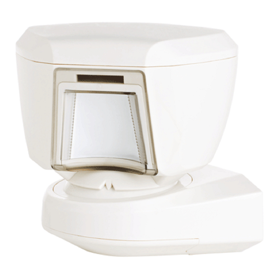
Figure 1.
General View
12m / 39 ft
3
4
5
-
1
Advertisement
Table of Contents

Related Manuals for Tyco TOWER-20AM


Summary of Contents for Tyco TOWER-20AM
- Page 1 TOWER-20AM PG2 PowerG Outdoor mirror PIR motion detector with anti-masking and built-in camera Installation Instructions 1. INTRODUCTION The TOWER 20 AM PG2 is a 2-way, wireless outdoor digital mirror PIR detector which includes the following features: Patented 8 independent quad PIR detectors (Octa-QUAD...
- Page 2 Correct Installation Incorrect Installation Callout Description Mark drilling point For wall tamper Drill Fasten Note: The 2 screw holes enable adjustment of the bracket on the wall if required after testing. Three long screw Two short screws Figure 2 - Installation HORIZONTAL ADJUSTMENT (-45°...
-
Page 3: Battery Insertion
VERTICAL ADJUSTMENT (0° to -10° in 2.5° clicks / steps) COVER CLOSURE Step Description Step Description Release locking Lock Adjust Turn cover and push Lock Put back cover Release locking Put back cover and secure with screw Adjust Figure 3 - Adjustment and Cover Closure Installation Notes: Do not obscure the detector field of view with large objects. -
Page 4: Configuring The Detector Parameters
2.3. Enrollment Refer to the PowerMaster control panel's Installer Guide and follow the procedure under the "02:ZONES/DEVICES" option of the Installer Menu. A general description of the procedure is provided in the following flow chart. Step 1 Step 2 Step 3 Step 4 Enter the Installer menu and select Select "ADD NEW DEVICE"... -
Page 5: Compliance With Standards
Important: Reliable reception must be assured. Therefore, "poor" signal strength is not acceptable. If you receive a "poor" signal from the detector, re- locate it and re-test until a "Good" or "Strong" signal strength is received. Note: For detailed Diagnostics Test instructions refer to the control panel Installer's Guide The LED blinking, described above, is operative only in Local diagnostic mode. -
Page 6: Appendix: Specifications
– Connect the device to an outlet on a circuit different from the one that supplies power to the receiver. – Consult the dealer or an experienced radio/TV technician. FCC Compliance Statement This device has been tested and found to comply with the limits for a Class B digital device, pursuant to Part 15 of the FCC Rules. These limits are designed to provide reasonable protection against harmful interference in residential installations. -
Page 7: Warranty
Mounting Type Wall mounting Mounting Height 1.5 – 3.0 m (5 – 10 ft). Horizontal Adjustment -45° to +45°, in 5° steps Vertical Adjustment 0° to -10°, in 2.5° steps ENVIRONMENTAL Operating Temperatures -35°C to 60°C (-31°F to 140°F) Storage Temperatures -35°C to 60°C (-31°F to 140°F) Humidity 95% max. - Page 8 JURISDICTIONS DO NOT ALLOW THE EXCLUSION OR LIMITATION OF INCIDENTAL OR CONSEQUENTIAL DAMAGES, SO THESE LIMITATIONS MAY NOT APPLY UNDER CERTAIN CIRCUMSTANCES. When accepting the delivery of the Product, the Purchaser agrees to the said conditions of sale and warranty and he recognizes having been informed The Manufacturer shall be under no liability whatsoever arising out of the corruption and/or malfunctioning of any telecommunication or electronic equipment or any programs.
Need help?
Do you have a question about the TOWER-20AM and is the answer not in the manual?
Questions and answers