
Related Manuals for Dalsa LinkHS HL-HF-16K10T-00-R


Summary of Contents for Dalsa LinkHS HL-HF-16K10T-00-R
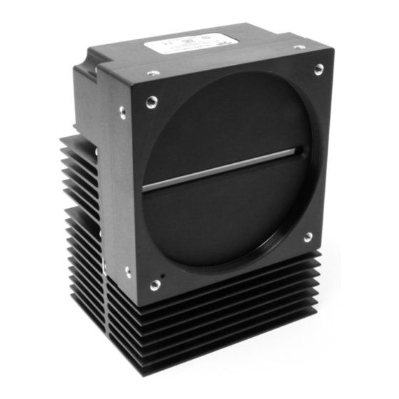
- Page 1 Linea HS Multifield Camera Multifield CMOS TDI HL-HF-16K10T-00-R sensors | cameras | frame grabbers | processors | software | vision solutions 03-032-20287-00 www.teledynedalsa.com...
- Page 2 All information provided in this manual is believed to be accurate and reliable. No responsibility is assumed by Teledyne DALSA for its use. Teledyne DALSA reserves the right to make changes to this information without notice. Reproduction of this manual in whole or in part, by any means, is prohibited without prior permission having been obtained from Teledyne DALSA.
-
Page 3: Table Of Contents
Contents THE LINEA HS MULTIFIELD CAMERA ESCRIPTION Multifield Technology AMERA IGHLIGHTS Key Features Programmability Applications UMBERS AND OFTWARE EQUIREMENTS PECIFICATIONS Camera Performance Environmental Specifications Flash Memory Size Certification & Compliance Responsivity & QE Camera Input Power ULTIFIELD IXEL RRANGEMENT AMERA ROCESSING HAIN UPPORTED... - Page 4 Internal Trigger Mode STABLISHING THE ESIRED ESPONSE Exposure Control by Light Source Strobe Image Response Uniformity & Flat Field Calibration Saving & Loading a PRNU Set Only Setting Custom Flat Field Coefficients Flat Field Calibration Filter Flat Field Calibration Regions of Interest MAGE ILTERS Kernels...
- Page 5 Communications Image Quality Issues Power Supply Issues Causes for Overheating & Power Shut Down DECLARATION OF CONFORMITY DOCUMENT REVISION HISTORY Linea HS Multifield Camera • 5...
-
Page 6: The Linea Hs Multifield Camera
Multifield is a new imaging technology that enables capturing multiple images using various lighting conditions (e.g. brightfield, darkfield, and backlight) in a single scan. Teledyne DALSA’s Linea multifield camera is the first product in the industry capable of capturing up to three images using light sources at different wavelengths. -
Page 7: Camera Highlights
Camera Highlights Key Features Highly sensitive CMOS TDI • • 16K pixel resolution • Up to 300 kHz line rates, aggregate • Very low noise Bi-directionality • Horizontal and Vertical Binning • Robust Camera Link HS interface • CX4 Camera Link HS control & data connector •... -
Page 8: Part Numbers And Software Requirements
5.0 x 5.0 µm Camera Link HS CX4 Table 2: Frame Grabber Compatible Frame grabber HL-HM-16K30H Teledyne DALSA Xtium2-CLHS PX8 (OR-A8S0-PX870) Other compatible frame grabbers may be available from third-party vendors. Table 3: Software Software Product Number / Version Number... -
Page 9: Specifications
Specifications Camera Performance Table 4: Camera Performance Specifications Specifications HL-HF-16K10T Notes Imager Format High speed CMOS TDI Resolution 16,384 pixels x 256 3 TDI arrays 64 + 128 + 64 stages Pixel Size 5.0 µm x 5.0 µm Pixel Fill Factor 100% Line Rate, maximum 100 kHz x 3... -
Page 10: Environmental Specifications
Full Well 25,000 e Typical 3,4) PRNU < ±2% At 50% saturation DSNU (FPN) < ±2 DN Blue 1.3 nJ/cm At 460 nm Green 1 nJ/cm At 560 nm Red 0.8 nJ/cm At 660 nm Blue 0.5 pJ/cm At 460 nm Green 0.4 pJ/cm At 560 nm Red 0.3 pJ/cm... -
Page 11: Responsivity & Qe
Responsivity & QE The following graphs show the spectral Responsivity and QE, 8-bit, 1x gain. Figure 1: Spectral Responsivity & QE Linea HS Multifield Camera • 11... -
Page 12: Camera Input Power
Camera Input Power The following graph details the power vs. input voltage for the camera. Camera Input Power 35.0 30.0 25.0 20.0 15.0 10.0 12.0 13.0 14.0 15.0 16.0 17.0 18.0 19.0 20.0 21.0 22.0 23.0 24.0 Voltage (V) Power @ 60°C (W) Power @ 25°C (W) Current @ 25°C (A) Current @ 60°C (A) -
Page 13: Multifield Pixel Arrangement
Multifield Pixel Arrangement 64 Lines 5 µm pixel gap of 35 lines 128 Lines 5 µm pixel gap of 35 lines 64 Lines 5 µm pixel Figure 3: Multifield Pixel Structure Forward and reverse imaging does not cause the optical center to change. Linea HS Multifield Camera •... -
Page 14: Camera Processing Chain
Camera Processing Chain The diagram below details the sequence of user-adjustable, arithmetic operations performed on the cameras sensor data. These adjustments are using camera features outlined in the ‘Review of Camera Performance and Features’ section. Figure 4: Digital data processing chain 14 •... -
Page 15: Genicam
Supported Industry Standards GenICam™ The camera is GenICam compliant and implements a superset of the GenICam Standard Features Naming Convention specification V1.5. This description takes the form of an XML device description file using the syntax defined by the GenApi module of the GenICam specification. The camera uses the GenICam Generic Control Protocol (GenCP V1.0) to communicate over the Camera Link HS command lane. -
Page 16: Cx4 Aoc Data Cables
Camera Link HS cables can be bought from OEMs, both is standard and flex models. Please refer to Teledyne DALSA’s website (www.teledynedalsa.com) for a list of recommended cable vendors and for part numbers. Each data cable is used for sending image data to and accepting command data from the frame grabber. -
Page 17: Mechanical Drawings
Mechanical Drawings Figure 6: HL-HF-16K10T-00-R Mechanical Drawing Linea HS Multifield Camera • 17... -
Page 18: Precautions
Precautions Read these precautions before using the camera. Confirm that the camera’s packaging is undamaged before opening it. If the packaging is damaged please contact the related logistics personnel. Do not open the housing of the camera. The warranty is voided if the housing is opened. Keep the camera’s front plate temperature in a range of 0 °C to +65 °C during operation. -
Page 19: Install & Configure Frame Grabber & Software
Install & Configure Frame Grabber & Software Because of the high bandwidth of these cameras, a compatible Teledyne DALSA frame grabber (Xtium2-CLHS PX8 (OR-A8S0-PX870)), or equivalent, is recommended. Details are described on the teledynedalsa.com site, here . Follow the manufacturer’s installation instructions. -
Page 20: Camexpert Panes
CamExpert Panes CamExpert, first instance: select Camera Link HS using the Device drop-down menu. Figure 7. CamExpert Frame Grabber Control Window The CamExpert application uses panes to organize the selection and configuration of camera files or acquisition parameters. Device Selector pane: View and select from any installed Sapera acquisition device. Once a device is selected, CamExpert will only show acquisition parameters for that device. - Page 21 Control Buttons: The display pane includes CamExpert control buttons. These are: Acquisition control button: Click once to start live grab, click again to stop. Single frame grab: Click to acquire one frame from device. Trigger button: With the I/O control parameters set to Trigger Enabled, click to send a single trigger command.
-
Page 22: Setting Up For Imaging
Setting Up for Imaging Figure 8. Camera I / O Connectors Camera I / O Connectors 1) Factory use only 2) Data and control connectors - CX4 3) LED status indicators 4) Power and GPIO connectors: +12 V to +24 V DC, Hirose 12-pin circular Powering the Camera WARNING: When setting up the camera’s power supply follow these guidelines:... -
Page 23: Power And Gpio Connections
Power and GPIO Connections The camera uses a single 12-pin Hirose male connector for power, trigger, and strobe signals. The suggested female cable mating connector is the Hirose model HR10A-10P-12S. 12-Pin Hirose Connector Signal Details The following figure shows the pinout identification when looking at the camera’s 12-pin male Hirose connector. - Page 24 External Input Electrical Characteristics Switching Voltage Input Level Standard Low to high High to low Input Impedance 10 K Ω 3.3 V TTL 2.1 V External Input Timing Reference Input Level Standard Max Input Min Pulse Input Current Maximum Signal Propagation Frequency Width Delay @ 60...
- Page 25 Mating GPIO Cable Assembly An optional GPIO breakout cable (12-pin Female Hirose to 13-Pos Euro Block) is available for purchase from Teledyne DALSA under accessory number #CR-GENC-IOP00 to order. Figure 10: GPIO cable accessory #CR-GENC-IOP00 Linea HS Multifield Camera • 25...
-
Page 26: Establishing Camera Communications
Establishing Camera Communications When powering up the camera, the status LED on the back will indicate one of the following conditions: LED State Description Camera is not powered up or is waiting for the software to start. Constant Red The camera BIST status is not good. See BIST status for diagnosis. CamExpert can be used to get the BIST value from the camera. -
Page 27: Camera Performance And Features
Camera Performance and Features This section is intended to be a progressive introduction to the features of the camera, including explanations of how to use them effectively. Synchronizing to Object Motion Acquiring Images: Triggering the Camera Related Features: Trigger Mode, Trigger Source, Trigger Activation A number of different methods can be used to trigger image acquisition in the camera: Internal Trigger The simplest method is to set the Trigger Mode feature to “Internal”. -
Page 28: Measuring Line (Trigger) Rate
6740 MB/s the following line rates were achieved: • 12-bit one colour: 200 kHz For advice on your setup and achieving higher line rates, contact Teledyne DALSA customer support. Minimum Line Rate The minimum line rate for the camera is 300 Hz. - Page 29 It is important to perform and save a flat field calibration in the actual system, both directions will be used. Direction Change Time The direction change time between forward and reverse is < 1 ms. Setting the correct scan direction Whether the scan direction is set correctly can easily be seen in live imaging.
-
Page 30: Camera Orientation
Camera Orientation The diagram below shows the orientation of forward and reverse with respect to the camera body. Note: The diagram assumes the use of a lens on the camera, which inverts the image. Figure 12: Example of Object Movement and Camera Direction (camera shown with lens) The diagram shows the designated camera direction. -
Page 31: Spatial Correction
Spatial Correction See Camera Control Category in Appendix A for GenICam features associated with this section and how to use them. Relevant Features: Line Spatial Correction Readout 64 Lines 5 µm pixel gap of 35 lines Readout 128 Lines 5 µm pixel gap of 35 lines Readout 64 Lines 5 µm pixel... - Page 32 The camera ensures the scan direction alignment of the three arrays by delaying the image data for each array a set amount of time, as dictated by the scan direction. If the encoder generates a pulse that is equal to the object pixel, the spatial correction value used by the camera will be 1.
- Page 33 Object Pixel Setup for 20 µm, Encoder set at 21 µm. Forward Scanning Can be corrected with 20 / 21 = 0.95 Spatial Correction If there are several different camera angles and associated illumination configurations in the inspection system, a single encoder pulse will not provide the correct timing for all the cameras. For example, as the camera angle moves away from perpendicular, the image row spacing increases.
-
Page 34: Imaging Modes
Imaging Modes See the section Camera Control Category in Appendix A for GenICam features associated with this section and how to use them Relevant Features: sensorTDIModeSelection The camera is capable of being run in the following modes: TdiRGB, TDIRed, TDIGreen, TDIBlue, TDIRedGreen, TdiRedBlue, TdiGreenBlue, TdiArea, TdiMultiArea. -
Page 35: Establishing The Desired Response
Establishing the Desired Response One of the important performance characteristics of the camera, is its Responsivity and associated noise level at the system’s maximum line rate and under desired illumination and lens configuration. Responsivity and noise performance can be assessed using a stationary, plain white target under bright field illumination. - Page 36 Using the GPIO controls the camera can be set up to strobe a light source effectively giving exposure control. Output Strobe Control Example Camera Trigger Trigger Delay Sensor Trigger Output Line 3, 4, 5 or 6 Output Duration Output Delay (Set to ≥...
- Page 37 Internal Timing Generation CLHS Framegrabber Exsync Trigger Delay Sensor Input Line 1 Trigger Activation Debouncer GPIO Connector Rotary Encoder Multiply-Divide Input Line 2 Trigger Activation Debouncer Output Line 3 Output Line Invert Output Duration Output Delay Output Line 4 Output Line Invert Output Duration Output Delay GPIO Connector...
-
Page 38: Image Response Uniformity & Flat Field Calibration
Image Response Uniformity & Flat Field Calibration See the section Flat Field Category in Appendix A for GenICam features associated with this section and how to use them. Related Features: Calibrate FPN, Calibrate PRNU, Calibration Algorithm, Calibration Target Images commonly have lower response at the edges of the camera’s field of view compared to its center. -
Page 39: Saving & Loading A Prnu Set Only
The Linea camera has many different modes of operation. It is strongly recommended that Note: the camera be flat fielded for that mode of operation that is intended including direction of scan Saving & Loading a PRNU Set Only See the section Flat Field Category in Appendix A for GenICam features associated with this section and how to use them. -
Page 40: Flat Field Calibration Filter
Flat Field Calibration Filter See the section Flat Field Category in Appendix A for GenICam features associated with this section and how to use them Related Feature: Calibration Algorithm If a sheet of material is being used as a white target, it must be completely free of blemishes and texture. -
Page 41: Image Filters
Image Filters Related Features: imageFilterMode, imageFilterType, imageFilterKernalSize, imageFilterContrastRatio The camera has a selection of image filters that can be used to reduce image noise. Use the feature imageFilterMode to turn the filtering on or off. Use the feature imageFilterType to read the type of filter that is being used. -
Page 42: Binning
Binning See the section Image Format Control Category in Appendix A for GenICam features associated with this section and how to use them. Related Features: BinningHorizontal and BinningVertical In certain applications, lower image resolution may be acceptable if the desired defect detection can still be achieved. -
Page 43: Steps To Setup Area Of Interest
Related Features: AOI Count, AOI Selector, AOI Offset, AOI Width If the camera’s field of view includes areas that are not needed for inspection (also refer to the description in the Flat Field Calibration Region of Interest section) then the user may want to ignore this superfluous image data. -
Page 44: Customized Linearity Response (Lut)
Look Up Table to upload a file. The file format is described in 03-084-20133 Linea Binary File Format which can be obtained from Teledyne DALSA Technical Support. This document also includes Excel spreadsheet examples. How to Generate LUT with CamExpert CamExpert can also be used to create a LUT file. - Page 45 11. Deselect the Lookup Table | Enable feature. 12. Return CamExpert to Pixel Depth = 8, and Image Buffer = 8-bits. Important points: • The frame grabber must be configured mono 12-bits in, 16-bits out. In the Parameters explorer a frame grabber feature must be selected, not a camera feature. •...
-
Page 46: Adjusting Responsivity And Contrast Enhancement
Adjusting Responsivity and Contrast Enhancement See the section Camera Control Category in Appendix A for GenICam features associated with this section and how to use them. Related Features: Gain Selector, Gain, Offset It is best for camera performance to always use the maximum exposure time possible based on the maximum line rate of the inspection system and any margin that may be required to accommodate illumination degradation. -
Page 47: Changing Output Configuration
Changing Output Configuration Pixel Format See the section Image Format Control Category in Appendix A for GenICam features associated with this section and how to use them Related Feature: Pixel Format The camera can output video data as 8-bit or 12-bit. Use the Mono8 Pixel Format to process image data as one, or two separate image planes. -
Page 48: Saving & Restoring Camera Setup Configurations
Saving & Restoring Camera Setup Configurations See the section Camera Information Category in Appendix A for GenICam features associated with this section and how to use them Related Features: Power-up Configuration Selector, UserSet1 thru UserSet16, User Set Selector, Power-on User Set, Current User Set An inspection system may use multiple illumination, resolution, and responsivity configurations in order to cover the different types of inspection it performs. -
Page 49: Active Settings For Current Operation
GenIcam Input By GenIcam Command By GenIcam Command 1 . Select a ‘Factory Set’ 1 . Select a ‘User Set’ 2 . Initiate a ‘User Set Load’ 2 . Initiate a ‘User Set Load’ Power Up Power Up Factory Setting Active Setting User Setting Or Reset... -
Page 50: Factory Settings
Factory Settings The factory setting is the camera settings that were shipped with the camera and which loaded during the camera’s first power-up. To load or restore the original factory settings, at any time, select the factory setting parameter and then select the user set load parameter. Note: By default, the user settings are set to the factory settings. -
Page 51: Appendix A: Genicam Commands
Features listed in the description table but tagged as Invisible are typically reserved for Teledyne DALSA Support or third party software usage, and not typically required by end user applications. The following feature tables describe these parameters along with their view attributes and in which version of the device the feature was introduced. -
Page 52: Camera Information Feature Descriptions
Camera Information Category Camera information can be retrieved via a controlling application. Parameters such as camera model, firmware version, etc. are read to uniquely identify the connected camera. These features are typically read-only. The Camera Information Category groups information specific to the individual camera. In this category the number of features shown is identical whether the view is Beginner, Expert, or Guru. - Page 53 Display Name Feature Description Device Version & View Manufacturer Info DeviceManufacturerInfo This feature provides extended manufacturer 1.00 information about the device. Indicates whether Beginner standard product or a custom camera(RO) Serial Number DeviceID Displays the device’s factory set camera serial 1.00 number.
- Page 54 Display Name Feature Description Device Version & View UserSet15 UserSet15 Select the user defined configuration UserSet 15 as the Power-up Configuration. UserSet16 UserSet16 Select the user defined configuration UserSet 16 as the Power-up Configuration. Load & Save UserSetSelector Selects the camera configuration set to load 1.00 Configuration feature settings from or save current feature...
- Page 55 Display Name Feature Description Device Version & View UserSet14 UserSet14 Select the User-defined Configuration space UserSet14 to save to or load from features settings previously saved by the user. UserSet15 UserSet15 Select the User-defined Configuration space UserSet15 to save to or load from features settings previously saved by the user.
-
Page 56: Built-In Self-Test Codes (Bist)
Built-In Self-Test Codes (BIST) In the Camera Information screen shot example above, the Power-On Status is showing ”Good”, indicating that the camera powered up without any problems. Details of the BIST codes can be found in the Trouble Shooting Guide in Appendix B. Camera Power-Up Configuration Selection Dialog CamExpert provides a dialog box which combines the GemICam features used to select the camera’s power-up state and for the user to save or load a camera state as a specific user set that... -
Page 57: Camera Control Category
Camera Control Category The camera control category, as shown by CamExpert, groups control parameters such as line rate, exposure time, scan direction, and gain. Figure 22: Camera Control Panel Camera Control Feature Descriptions Display Name Feature Description Device Version & View Device Scan Type DeviceScanType Displays the device scan type. - Page 58 Display Name Feature Description Device Version & View TDI Mode sensorTDIModeSelection Select the TDI mode for the sensor. 1.00 TdiRGB Beginner TDI RGB TDI RGB TdiRed TDI Red TDI Red TdiGreen TDI Green TDI Green TdiBlue TDI Blue TDI Blue TdiRedGreen TDI RedGreen TDI RedGreen...
-
Page 59: Digital I / O Control Feature Descriptions
Display Name Feature Description Device Version & View Save Image To Flash saveLastImageToFlash Captures the current line and saves it to the cameras 1.00 Flash memory as a TIFF file that can be retrieved using Guru the File Access Control Features Digital I / O Control Feature Descriptions The camera’s Digital I / O Control category is used to configure the cameras GPIO pins. - Page 60 Trigger Source TriggerSource Determines the source of external trigger 1.00 DFNC Beginner CLHS In CLHS In Source of trigger is from the frame grabber Rotary Encoder Rotary Encoder Source of trigger is from the shaft encoder inputs Line 1 GPIO1 Source of trigger is from Line 1 of the GPIO connector Determines which edge of a input trigger will activate...
- Page 61 Trigger Delay TriggerDelay Allows the trigger to the sensor to be delayed 1.00 relative to camera input trigger DFNC Beginner Line Selector LineSelector Selects the physical line (or pin) of the external 1.00 device connector to configure. DFNC Beginner Index of the physical line and associated I/O control Line 1 GPIO 1 block to use.
-
Page 62: Flat Field Category
Flat Field Category The Flat Field controls, as shown by CamExpert, group parameters used to control the FPN and PRNU calibration process. Figure 24: Flat Field Panel 62 • Appendix A: GenICam Commands Linea HS Multifield Camera... -
Page 63: Flat Field Control Feature Description
Flat Field Control Feature Description Display Name Feature Description Device Version & View Flat Field Correction Mode flatfieldCorrectionMode 1.00 FPN and PRNU correction Beginner disabled. FPN and PRNU correction DFNC enabled. Clear Coefficents flatfieldCalibrationClearCoefficient Reset all FPN to 0 and all flat field coefficients to 1. - Page 64 Display Name Feature Description Device Version & View Row Selector flatfieldCalibrationColorSelector Specify which sensor rows to 1.00 perform PRNU calibration on, all Beginner or individual colors. DFNC Calibrate PRNU flatfieldCalibrationPRNU Initiates the Flat Field (PRNU) 1.00 calibration process Beginner DFNC Flat Field Correction Current flatfieldCorrectionCurrentActiveSet Selects the User PRNU set to be...
-
Page 65: Image Format Control Category
Image Format Control Category The camera’s Image Format controls, as shown by CamExpert, group parameters used to configure camera pixel format, image cropping, binning and test pattern generation features. Figure 25: Image Format Panel Linea HS Multifield Camera • 65... -
Page 66: Image Format Control Feature Description
Image Format Control Feature Description Display Name Feature Description Device Version & View PixelFormat Output image pixel coding format of the 1.00 Pixel Format sensor. Beginner SFNC Mono8 Mono8 Mono12 Mono12 BGR 8 RGB8_Planar BGR 12 RGB12_Planar Pixel Size PixelSize Total size in bits of an image pixel. - Page 67 FileAccess > Miscellaneous > User PRNU feature. The PRNU coefficient will be applied to a midscale (128DN) test image. Contact Teledyne DALSA support for an Excel file that can help with this. AOI Count multipleROICount Specified the number of AOI’s in an 1.00...
- Page 68 Hor16 16 pixels between horizontal alignment markers Hor32 32 pixels between horizontal alignment markers Hor64 64 pixels between horizontal alignment markers Hor128 128 pixels between horizontal alignment markers Alignment Marker alignmentMarkerHorizontalOffset Pixel count before first horizontal Horizontal Offset alignment marker. Integer between 0 and alignmentMarkerHorizontalSpacing value.
-
Page 69: Transport Layer Control Category
Transport Layer Control Category Note: All features shown in Guru visibility. Figure 27: Transport Layer Panel Linea HS Multifield Camera • 69... -
Page 70: Transport Layer Feature Descriptions
Transport Layer Feature Descriptions Display Name Feature Description Device Version & View XML Major Version DeviceManifestXMLMajorVersion Together with 1.00 DeviceManifestXMLMinorVersion Beginner DFNC specifies the GenICam™ feature description file version (RO) XML Minor Version DeviceManifestXMLMinorVersion Together with 1.00 DeviceManifestXMLMajorVersion Beginner DFNC specifies the GenICam™... -
Page 71: Acquisition And Transfer Control Category
Acquisition and Transfer Control Category Figure 28: Acquisition & Transfer Control Panel Acquisition and Transfer Control Feature Descriptions Display Name Feature Description Device Version & View Acquisition Mode AcquisitionMode The device acquisition mode defines the number of frames to 1.00 capture during an acquisition and the way it stops Beginner DFNC... -
Page 72: File Access Control Category
File Access Control Category The File Access control in CamExpert allows the user to quickly upload and download of various data files to/from the connected the camera. The supported data files for the camera include firmware updates and Flat Field coefficients. Note: The communication performance when reading and writing large files can be improved by stopping image acquisition during the transfer Figure 29: File Access Control Panel... -
Page 73: File Access Control Feature Descriptions
File Access Control Feature Descriptions Display Name Feature Description View File Selector FileSelector Selects the file to access. The file types which are accessible are 1.00 device-dependent. Beginner All Firmware Upload micro code, FPGA code &XML as a single file to the DFNC camera which will execute on the next camera reboot cycle. -
Page 74: File Access Via The Camexpert Tool
File Access via the CamExpert Tool 1. Click on the “Setting…” button to show the File Access Control dialog box. Figure 30: File Access Control Tool 2. From the Type drop menu, select the file type that will be uploaded to the camera or downloaded from the camera. -
Page 75: Clhs File Transfer Protocol
CLHS File Transfer Protocol If you are not using CamExpert to perform file transfers, pseudo-code for the CLHS File Transfer Protocol is as follows. Download File from Camera Select the file by setting the FileSelector feature • Set the FileOpenMode to Read •... -
Page 76: Download A List Of Camera Parameters
3. In the “Type” drop down box select “Miscellaneous.” 4. In the “File selector” drop down box select “CameraData.” 5. Hit “Download” 6. Save the text file and send the file to Teledyne DALSA customer support. 76 • Appendix A: GenICam Commands Linea HS Multifield Camera... -
Page 77: Appendix B: Trouble Shooting Guide
The camera data file includes the operational configuration and status of the camera This text file can be downloaded from the camera and forwarded to Teledyne DALSA Technical Customer support team to aid in diagnosis of any reported issues. See Saving & Restoring Camera Setup Configurations of the user manual for details on downloading the Camera Data file. - Page 78 Built-In Self-Test Codes The Built-In Self-test (BIST) codes are located in the Camera Information pane under Power-on Status. None of these should occur in a properly functioning camera except OVER_TEMPERATURE. OVER_TEMPERATURE occurs if the ambient temperature is too high, there is insufficient air circulation or heat sinking.
-
Page 79: Resolving Camera Issues
Resolving Camera Issues Communications No Camera Features when Starting CamExpert If the camera’s CamExpert GUI is opened and no features are listed, then the camera may be experiencing lane lock issues. While using the frame grabber CamExpert GUI you should be able to see a row of status indicators below the image area that indicates the status of the CLHS communications. -
Page 80: Image Quality Issues
Image Quality Issues Vertical Lines Appear in Image after Calibration The purpose of flat field calibration is to compensate for the lens edge roll-off and imperfections in the illumination profiles by creating a uniform response. When performing a flat field calibration, the camera must be imaging a flat white target that is illuminated by the actual lighting used in the application. - Page 81 Smeared & Distorted Images To achieve a well-defined image, the multiple lines are summed together and delayed in a manner that matches the motion of the image across the sensor. This synchronization is achieved by sending an external synchronization (EXSYNC) signal to the camera, where one pulse is generated when the object moves by the size of one object pixel.
-
Page 82: Power Supply Issues
Over-speeding may be due to inertia and / or backlash in the mechanical drive mechanism, causing variations around the target speed. The greater the speed variation, the lower the target speed needs to be to avoid over-speed conditions. If the speed variation can be reduced by eliminating the backlash in the transport mechanism and / or optimizing the motor controller characteristics, then a higher target speed will be achievable. -
Page 83: Causes For Overheating & Power Shut Down
Causes for Overheating & Power Shut Down For reliable operation, the camera’s face plate temperature should be kept below +65 °C and the internal temperature kept below +70 °C. Many applications, such as in clean rooms, cannot tolerate the use of forced air cooling (fans) and therefore must rely on convection. -
Page 84: Declaration Of Conformity
Declaration of Conformity 84 • Declaration of Conformity Linea HS Multifield Camera... -
Page 85: Document Revision History
Document Revision History Revision Description Date Initial release. 29 November 2019 Linea HS Multifield Camera • 85...
Need help?
Do you have a question about the LinkHS HL-HF-16K10T-00-R and is the answer not in the manual?
Questions and answers