Advertisement
Quick Links
Copyright
Copyright Notice: The information in this manual is subject to change without prior notice in order to improve
reliability, design and function and dosed not represent a commitment on the part of the manufacturer. No part of this
manual may be reproduced, copied, or transmitted in any form without the prior written permission of manufacturer.
Acknowledgment Products mentioned in this manual are mentioned for identification purpose only. Products manes
appearing in this manual may or may not be registered trademarks or copyright of their respective companies.
cele mai sensibile
Electric Film S.R.L. — Aleea Scarisoara 3, Apt.42 ▪ Cluj Napoca, Cluj ▪ 400445 ▪ www.electricfilm.eu
VÂNZĂRI ▪ 0364 710319 ▪ electricfilm.eu@gmail.com ▪ SUPORT TEHNIC ▪ 0788 250583
TRP-C31S
User's Manual
Ethernet To RS232/422/485 Converter
Trycom Technology Co., Ltd
1F, No.2-11, Sihu street, Yingge Township, Taipei, Taiwan ROC
Tel: 886-2-86781191, Fax: 886-2-86781172
Web: www.trycom.com.tw
ECHIPAMENTE PENTRU AUTOMATIZĂRI
Printed Jan. 2008 Rev 1.0
Advertisement

Related Manuals for Trycom Technology TRP-C31S


Summary of Contents for Trycom Technology TRP-C31S
- Page 1 TRP-C31S User’s Manual Ethernet To RS232/422/485 Converter Printed Jan. 2008 Rev 1.0 Trycom Technology Co., Ltd 1F, No.2-11, Sihu street, Yingge Township, Taipei, Taiwan ROC Tel: 886-2-86781191, Fax: 886-2-86781172 Web: www.trycom.com.tw Copyright Copyright Notice: The information in this manual is subject to change without prior notice in order to improve reliability, design and function and dosed not represent a commitment on the part of the manufacturer.
- Page 2 DIN rail design enables fast and professional installation. The TRP-C31S operates in “Direct IP Mode”, “Virtual COM Mode”, and “Paired Mode”. It has one synchronous DB-9 serial port for RS232 connection and screw terminal block for RS422/485 connection.
-
Page 3: Hardware Description
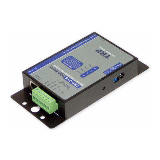
2. Hardware Description The following information is provided to give the user an understanding of how to connect the TRP-C31S to the LAN and serial device. A review of the switch settings and the functionality of the LED’s are also provided. - Page 4 Hold for 3 seconds and release. The Link and Run light will go out and turn back on. The TRP-C31S will revert to the last setting. 2-4. Dip Switches A double DIP switch allows the TRP-C31S to be placed into default/ Loop Back/Factory/console Mode.
- Page 5 4. Install TRP-C31S Hardware STEP1: Connect power source with TRP-C31S. The TRP-C31S has a two pins terminal block and power jack. Power can apply on either terminal block or the power jack. It accepts DC+10V~30V power supply. When power is properly applied the PWR LED will flash every one second to indicate the system is up and running.
- Page 6 A straight-through Ethernet cable can be used to connect TRP-C31S to an Ethernet hub, switch, or wall plate. A crossover Ethernet cable can be used to make a connection directly to the NIC (Network Interface Card) on a PC or laptop STEP3: Connect TRP-C31S with RS232 or RS422/485 serial device.
- Page 7 5. Install “TRP-C3X Manager” Utility It is recommended the user install the “TRP-C3X Manager” utility software and do a search for all TRP-C31S connected to the LAN. When this is completed a window will list the devices making them available for configuration.
- Page 8 STEP3. Click the “Next” to continue the installation. STEP4. In the Choose Destination Location window select “Next” to install the “TRP-C3X Manager” software in the default location. (User may select “Browse” to install into a selected directory) The installation progress will be shown until complete. cele mai sensibile ECHIPAMENTE PENTRU AUTOMATIZĂRI Electric Film S.R.L.
-
Page 9: Updating An Existing Installation
Highlight remove. 7. How to configure TRP-C31S There are 4 ways to access the Server Properties and program the TRP-C31S 1. TRP-C3X Manager software, see 7-1. 2. Console mode, see 7-2. 3. Telnet, see 7-3. 4. Web Server, see 7-4. - Page 10 H: Saving and Loading Configuration Files 7-1-1.Searching LAN for TRP-C31S Once TRP-C31S is connected to the LAN the TRP-C3X Manager software will search it and display it in a window by name and IP address. A. Select “TRP-C3X Manager” Utility in the program file menu. If the default location was selected during the installation the program will be found under “Start/Programs/Trycom...
- Page 11 7-1-2.Configuring Server Properties Highlight the serial server in the Serial Server List window and double click to open the Server Properties window. The Server Properties window is used to configure and store the Server configuration settings. Details for setting Properties are described in the next chapter. After configuring as needed, click Update to store the configuration in the server and click “Yes”...
- Page 12 IP address, netmask, and gateway to the TRP-C31S. If a DHCP server is not available on the network the TRP-C31S will time out after 10 seconds and the default values will remain. When DHCP is enabled, the IP address, Netmask and Gateway fields become inaccessible and cannot be changed by the user.
- Page 13 (Saved) or the serial server will not retain them. Baud Rate The serial port baud rate on the TRP-C31S must match the serial baud rate of the connected device unless using Virtual COM mode. In Virtual COM mode the software program will establish serial settings.
- Page 14 Ethernet port. If only Delimiter 1 is set (Delimiter 2 is zero or blank), upon receiving Delimiter 1 the TRP-C31S will put all the data in the serial buffer in an Ethernet packet and send it out the Ethernet port. If serial data greater than 1 kilobyte is received it will automatically be placed in an Ethernet packet and sent out the Ethernet port.
- Page 15 When the Connection Mode field is set to Client or Client (no heartbeat), this field becomes active, allowing the TRP-C31S (acting as a client) to connect to the server either on Power up or on Data Arrival (first character arriving).
- Page 16 A serial connection is made between a COM port on the PC and the TRP-C31S serial port A with a null modem cable. In console mode, the serial port defaults to an RS-232 interface.
- Page 17 7-2-1 Console Mode Hardware Wiring 7-2-2 Console Mode Software Install STEP1. Select “Hyper Terminal” WINDOWS Utility Start ---Accessories---Communications --- Hyper Terminal STEP2.Select “New Connection” and Enter a name, click “OK” cele mai sensibile ECHIPAMENTE PENTRU AUTOMATIZĂRI Electric Film S.R.L. — Aleea Scarisoara 3, Apt.42 ▪ Cluj Napoca, Cluj ▪ 400445 ▪ www.electricfilm.eu VÂNZĂRI ▪...
- Page 18 You can set the TRP-C31S by Console mode. 7-3.Using Telnet Telnet can be used to configure the TRP-C31S Serial Server from any PC on the LAN. The Telnet window displays the same configuration information shown in Console Mode and allows server properties to be configured.
- Page 19 STEP1. Select Start then Click “RUN” then key in the “Telnet IP” STEP2. Click the “OK” TRP-C31S firmware setting will show as following screen. You can set the TRP-C31S by Telnet mode. cele mai sensibile ECHIPAMENTE PENTRU AUTOMATIZĂRI Electric Film S.R.L. — Aleea Scarisoara 3, Apt.42 ▪ Cluj Napoca, Cluj ▪ 400445 ▪ www.electricfilm.eu...
- Page 20 7-4 Using the WEB Server mode The Web Server can be used to configure the TRP-C31S Serial Server from any web browser software (such as Internet Explorer). Server properties can be set up using three browser pages. See chapter 6 for details on Server Properties.
-
Page 21: Virtual-Com
The COM port will look like a standard COM port to Windows software used in most applications allowing the software to open a connection with the serial port located anywhere on the LAN. When using the virtual COM port the TRP-C31S is configured as a TCP or UDP Server. - Page 22 The Virtual COM port can be configured in the Device Manager of the operating system or the Manager software. In either case the IP Address, Port #, Protocol, and Flow Control settings must match the TRP-C31S settings for the software to open the Virtual COM port. cele mai sensibile ECHIPAMENTE PENTRU AUTOMATIZĂRI...
- Page 23 STEP1. At the Desk Top select Start/Program/Trycom/TRP-C3X Manager. Double click the Virtual COM Configuration button. STEP2. Double click the COM # displayed in the screen to open the configuration window. STEP3. Make the adjustments and select OK to complete the changes. 8-2-1 Configuration with Device Manager STEP1.
- Page 24 STEP3. In the Device Manager select the + button next to Ports (COM & LPT) to expand and see the TRP-C31S (COM #). Double click TRP-C31S (COM #) to open the Properties window. STEP4. Select the Configuration tab. From here the same settings found in the TRP-C31S Manager can be adjusted.
- Page 25 + next to Ports (COM & LPT) to expand. STEP3. Highlight TRP-C31S (COM #) to be removed, go the Action tab at the top of window and select uninstall. A confirm Device Removal window will appear. Select OK to proceed.
- Page 26 The Virtual COM mode requires the installation of a driver. When installed a new COM port is added to the Device Manager. Windows programs using standard Windows API calls will be able to interface with Virtual ports. The PC will act as the host connecting to the TRP-C31S when the program opens the virtual COM port.
- Page 27 TRP-C31S and the LAN. Two TRP-C31S are configured with one setup as a TCP or UDP client and the other to TCP/UDP server. When setting up the Server, the Remote IP address section must contain the address of the Client.
- Page 28 User can directly link TRP-C31S to Trycom Remote IO Modules by RS485, The basic wiring connect. 11.RS232/422 Loop Test STEP1. Adjust the TRP-C31S’s Switch to the “ON, OFF” STEP2. Run the “Install Virtual-Com” and setting the Virtual-COM. STEP3. Run the Demo Utility, click the “Settings” then setup the com port status and click the “Action”!
Need help?
Do you have a question about the TRP-C31S and is the answer not in the manual?
Questions and answers