Advertisement
Quick Links
Download this manual
See also:
User Manual
Copyright
Copyright Notice: The information in this manual is subject to change without prior notice in order to improve
reliability, design and function and dosed not represent a commitment on the part of the manufacturer. No part of this
manual may be reproduced, copied, or transmitted in any form without the prior written permission of manufacturer.
Acknowledgment Products mentioned in this manual are mentioned for identification purpose only. Products manes
appearing in this manual may or may not be registered trademarks or copyright of their respective companies.
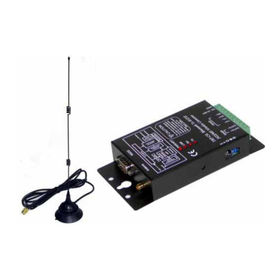
TRP-C51
User's Manual
Bluetooth To RS232/422/485 Converter
User Manual
Printed DEC. 2007 Rev 1.0
Advertisement

Related Manuals for Trycom Technology TRP-C51


Summary of Contents for Trycom Technology TRP-C51
-
Page 1: User Manual
TRP-C51 User’s Manual Bluetooth To RS232/422/485 Converter User Manual Printed DEC. 2007 Rev 1.0 Copyright Copyright Notice: The information in this manual is subject to change without prior notice in order to improve reliability, design and function and dosed not represent a commitment on the part of the manufacturer. No part of this manual may be reproduced, copied, or transmitted in any form without the prior written permission of manufacturer. - Page 2 Based on Bluetooth technology TRP-C51 allows you to wirelessly connect your RS232/422/485 devices to systems within the range over to 100M, TRP-C51 features wide range power input, auto RS232/422/485 signal switching and internal surge protection on RS422/485 lines. It also supports all common data format and baud rate which can be configured by the bundled TRP-BT utility from Windows system.
- Page 3 LED indicator: Power, Link, TX, and RX. Power input type: Screw terminal or DC plug.(5.5*2.1*12mm/500mA) Power consumption: 1.2 watt. Operating temperature: 0 to 50 . Storage temperature: -20 to 65 . Humidity: 10-90% Non-condensing. Dimension: 151mm X 75mm X 26mm. Weight: 400g.
- Page 4 Blinking— When there is activity such as data transmitting or receiving. TX LED: RS232/422/485 data transmitting. RX LED: RS232/422/485 data receiving. 2-4. DIP Switch There are 2 dip switch on TRP-C51. One 2-pin dip switch is for system configuration, another is a 4-pin dip switch for extension and no function.
- Page 5 TRP-C51 micro touch button provides user with “new link” function when user want to drop existing connection and create a new connection with new device. The Micro touch button can only work when TRP-C51 is defined as Master. When TRP-C51 is in Slave mode the button is no function.
- Page 6 If the power input from external, Please use the power plug specification. (5.5*2.1*12 mm). Warning: User can only choose one of following 2 power sources. 1. External DC adapter. 2. Screw terminal DC input Do not use both power input simultaneously. 3-3.
- Page 7 Step1. Use a Null modem cable (crossover female to female cable) to make a connection between the TRP-C51 DB-9 connector and PC DB-9 connector. Step.2 Run the TRP-BT Utility by window User may find the TRP-BT utility in TRP-C51 support CD.
- Page 8 TRP-BT.EXE the configuration screen appears. Step.3. Adjust 2-PIN SW to the ON, ON position (System configuration Mode) then power on TRP-C51. Step.4. Select the PC RS232 COM Port for TRP-C51. Step.5 Click the “Read Configuration” button to read the TRP-C51 firmware configuration.
- Page 9 Step.6 Select the baud rate from 1200 bps ~ 256 K bps. Step.7 Select the data bit form 5~8.
- Page 10 Step 8 Select the Parity Check. Step 9 Select the Stop Bit. Step 10 Select the RTS/CTS Flow Control. *It must be disable if the user using the RS422/485 function.
- Page 11 TRP-C51 can be defined as Master device, or Slave device here. If define TRP-C51 as a Master, and input a Slave BD address, this Master of TRP-C51 will search only for the matched BD address of Slave device. 5. How to use TRP-C51 TRP-C51 support direct link mode and paired connection mode.
- Page 12 TRP-C51; however TRP-C51 is compatible with most of USB dongle in the market. User may use own USB dongle for Bluetooth interface. In the next TRP-C51 operating descriptions we use ET-BD121 as example. 5-1. Direct link mode Step1 Power on TRP-C51 and select TRP-C51 as slave.
- Page 13 Step5 Click on “New connection “icon into the Add New Connection Wizard, the USB dongle start to search all discoverable TRP-C51 units. Suppose just only 1 TRP-C51 unit need to be installed, we can see there is only one Bluetooth device been searched with the device name...
- Page 14 Step6 Select installation mode. Select Express Mode: The COM port is assigned by system. Custom Mode: Allow user freely to assign the COM Port to TRP-C51 Confirm with “Next>” In the next description we select “Custom mode” for explanation. Step7: Assign a appropriate COM port for TRP-C51 and confirm with “Next>”.
- Page 15 User may rename or delete the TRP-C51 here. Select “Connect” option you are requested a Bluetooth passkey. Please Input TRP-C51 password which must be same as the setting by TRP-BT utility, press OK, TRP-C51 will go into searching mode, the LINK LED start to fast blinking.
- Page 16 User may back to the Windows screen and Click Start – Program file – Bluetooth – Bluetooth setting to start the second TRP-C51 installation. The number of TRP-C51 that a Host system may install is depended on the COM Port number that the system or OS can offer.
- Page 17 6. How to test TRP-C51 The demo and test utility, these utilities may help user to demo and test TRP-C51 fast and easily. User may find the utilities in support CD. The testing utility includes RS422 test utility test422.exe for DOS...
- Page 18 6-2.RS422 Loop Back Test RS422 loop back test wiring connection. 6-3.Loop Back Test Software Step1.Run the “DEMO.EXE” utility (See the Figure 5). Fig.5 Step2.Click the “Setting” to set the RS422 loop counter (See the Figure 6); your system will detect the COM3. Fig.6 * Please note: “COM3”...
- Page 19 Step1. Install TRPCOM utility. TRPCOM is a test utility which may help user to test TRP-C51 with RS485 device easily. User may find the utility in the TRP-C51 support disk. Double click “Setup.exe”, the install Wizard will guide you to complete the installation.
- Page 20 Step3.Send command “$01M” and press “Send”. Step4. Data response received. Test complete.
Need help?
Do you have a question about the TRP-C51 and is the answer not in the manual?
Questions and answers