Advertisement
Quick Links
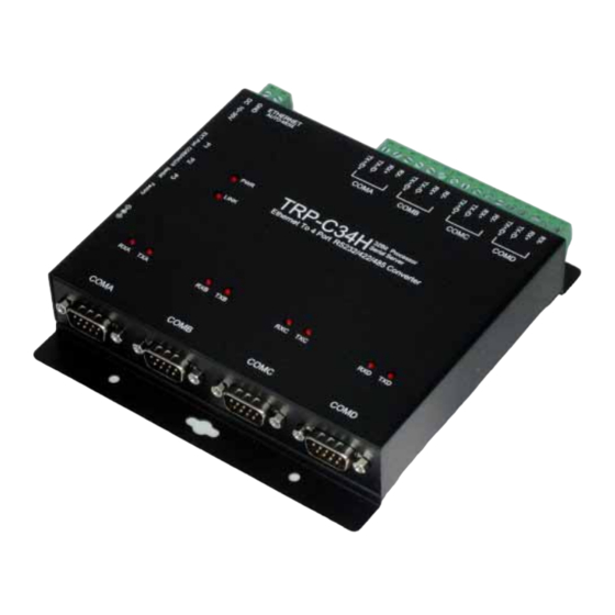
TRP-C34H
Ethernet to 4 RS232/422/485 Converter
User's Manual
Printed Mar. 2011 Rev 1.0
Trycom Technology Co., Ltd
1F, No.2-11, Sihu street, Yingge Township, Taipei, Taiwan ROC
Tel: 886-2-86781191, Fax: 886-2-86781172
Web: www.trycom.com.tw
Copyright
Copyright Notice: The information in this manual is subject to change without prior notice in order to improve
reliability, design and function and dosed not represent a commitment on the part of the manufacturer. No part of this
manual may be reproduced, copied, or transmitted in any form without the prior written permission of manufacturer.
Acknowledgment Products mentioned in this manual are mentioned for identification purpose only. Products manes
appearing in this manual may or may not be registered trademarks or copyright of their respective companies.
Advertisement

Related Manuals for Trycom Technology TRP-C34H


Summary of Contents for Trycom Technology TRP-C34H
- Page 1 TRP-C34H Ethernet to 4 RS232/422/485 Converter User’s Manual Printed Mar. 2011 Rev 1.0 Trycom Technology Co., Ltd 1F, No.2-11, Sihu street, Yingge Township, Taipei, Taiwan ROC Tel: 886-2-86781191, Fax: 886-2-86781172 Web: www.trycom.com.tw Copyright Copyright Notice: The information in this manual is subject to change without prior notice in order to improve reliability, design and function and dosed not represent a commitment on the part of the manufacturer.
- Page 2 IP: Port Number of the TRP-C34H’s Serial Port to a local COM Port on the host computer. The important point is that Real COM Mode allows users to continue using RS-232/422/485 serial communications software like HyperTerminal and similar applications.
- Page 3 RS485 data without lost, Specify hardware can ensure on line RS485 device working fine. The TRP-C34H has four synchronous D SUB 9 pin serial port for RS232 connection and 4 screw terminal block for RS422/485 and power connection. The Ethernet port support Auto-MDIX and Auto-select 10/100MB.
- Page 4 Din rail or panel mounts support. 1-2 . Specification. CPU:32 bit 170MHZ with MMU. SDRAM:32MB. FLASH:8MB. Power Input Voltage: DC +10V to +30V. LAN: Auto-MDIX, 10/100 Mbps Auto-detecting. RS-232: RI,TX, RX, RTS, CTS, DTR, DSR, DCD, GND. RS-422: TX+, TX-, RX+, RX-. RS-485: Data +, Data –.
- Page 5 1-3. TRP-C34H Support 3 TRP-C08X Diagram. TRP-C34H is a system level solution with four RS232/422/485 serial ports connected to three TR-C08X to support 16 serial port interfaces,TRP-C08X connected to any of the P1/P2/P3 Ports of TRP-C34H to support 8/12/16 Serial Port interfaces. Each TRP-C08X can provide four RS232/RS422/RS485 Serial Ports.
- Page 6 2. Hardware Description. 2-1. Panel layout and Dimension. mm/Unit. Notice: User can only choose either external DC-Jack or Screw terminal DC input. Do not use DC-Jack and screw terminal DC input simultaneously.
- Page 7 2-2. LED indicators. PWR LED: Blinking: Not Ready. ON: Stand By. LINK LED: Ethernet cable connection and data active. TX/RX LED: COMA~COMD RS232/422/485 Transiting/Receiving Indicator. DC Jack: Power Input DC +10V to +30V. (Pleas use the 5.5*2.1mm DC JACK). 2-3. Factory default. * Push the factory restore button till the PWR LED off and then reboot.
- Page 8 Operating Mode: Real Com Mode. Accessible IPs: None Setting. Auto Warning: None Setting. IP Address Report: None Setting. Password: Factory: trycom 2-4. DIP Switches. There are 4 DIP switch allows the TRP-C34H adjust to RS232 or RS422/485 Inside of the box.
- Page 9 *Please use screwdriver and then open back of metal, adjust the switch to select RS232 or RS422/485. 2-5. Push Button. If lost the password or IP, user can keep push button for restore factory default till the PWR LED off and then reboot. 2-6.
- Page 10 STEP3: Connect TRP-C34H with Ethernet port by RJ45 cable. If the cable is properly connected the “LINK” LED will light up. *The TRP-C34H Support Auto-MDIX, A straight-through or crossover RJ45 cable can be used to make a connection directly to the HUB/Router/PC LAN port.
- Page 11 4. How to configure TRP-C34H. There are 3 ways to access the TRP-C34H. a. Serial Server Admin Utility. b. WEB Server.
- Page 12 c. Telnet. 4-1. Installing Serial Server Admin Utility. The “Serial Server Admin Utility” Support WIN XP/VISTA/2003 Server/2008 Server 32/64 bit, 2000 Server/Win 7.
- Page 13 Double Click on the Serial Server Admin Utility then Right click on the main window or go to Server Manager in Menu Bar and select Search Devices to find the TRP-C34H on the network. By default all the devices searched are locked and can be seen under the status column of the Server Manager Window in order to protect from unauthorized configuration changes.
- Page 14 This invokes the Server Manager Configuration Dialog as shown below. On Basic page, check the Modify check Box to change any of the Configuration details. IP Setting:...
- Page 15 On IP Settings Page, click the modify box first, you can modify all the Network parameter a. IP address b. Net Mask c. Gateway d. Click the IP Configuration drop-down box, to modify the parameter Static/DHCP/BOOTP. e. DNS Server 1: When the user wants to visit a particular website, the computer asks the Domain Name System (DNS) Server for the website’s correct IP address, and the computer uses the response given by DNS Server to connect to the Web Server.
- Page 16 Contact: The SNMP contact information usually includes an emergency contact name and telephone or pager or Mobile number. i. Location: This string is usually set to the street address where the TRP-C34H is physically located. Port Settings Page On the Port Settings page of the Server Manager dialog displays all the serial ports, present on the Serial Server model of the selected device.
- Page 17 Select any port and click on “View Settings” tab which shows the “Operating Mode” dialog Box as shown below. The default operating Mode is “Real Com” Mode. Note. TRP-C34H will restart automatically, after configuring the Operating Settings page. For all other pages, TRP-C34H will not restart.
- Page 18 TCP Server Mode a. Local TCP Port: The TCP Port of TRP-C34H that uses to listen to the requests coming from Host Computers on Network in order to establish connection. The Host Computers should contact this Port in order to establish connection with the TRP-C34H.
- Page 19 Setting Destination IP address 1 and Port Number, allows TRP-C34H to connect actively to the remote host whose address is set by this parameter. c. Similarly Destination IP addresses 2 / 3 / 4, allows TRP-C34H to connect actively to the remote hosts whose address is set by this parameter.
- Page 20 On “Accessible IP’s” page , click the modify box to activate the parameter, Click on settings button to enter the IP Address and Net Mask of remote host that control the TRP-C34H . You can allow one of the following cases by setting the parameter.
- Page 21 Auto warning mechanism is a useful mechanism which sends the status messages to E-Mail id’s and Trap Servers in order to warn or acknowledge the changes made to the TRP-C34H . On Auto warning page under E-mail and SNMP Trap Setting Tab, click the modify box to activate the parameter.
- Page 22 e. Input the User Name and Password to modify the Mail Server Authentication Setup. f. To set or modify the Trap Server , check the Modify checkbox and enter the IP Address or Domain name of the Trap Server to which the Auto warning are to be sent. On Auto warning page, under Event Tab, click the Modify box to activate the parameter, and click the checkbox to set the Events for which Auto warnings are to be sent.
- Page 23 Network management becomes difficult when TRP-C34H is forced into DHCP. Any IP changes due to DHCP in TRP-C34H are reported to the assigned Host on the Network. On IP address Report, click the modify box to activate the parameter, and set the IP address,...
- Page 24 Password Password can be set / modified & Disabled through this screen. Maximum length of 7 characters can be supported for TRP-C34H password. Alpha, Numeric & Alpha numeric type of passwords are supported. Space is not allowed between any characters in password.
- Page 25 4-3. Telnet. TRP-C34H implements a Telnet Server and can be invoked by making a Telnet from remote PC. In the “Basic Settings” page of “Windows Configuration Utility”, if the ‘Enable Telnet Console’ check box is enabled we can use the Telnet Console to modify the device parameters.
- Page 26 5. Application. 5-1. Real COM Mode. TRP-C34H Basic 4 Real COM Port installs. Example: Step1: Connect PC-----RJ45-----TRP-C34H-----RS232/422/485 Device. Step2: Run “Serial Server Admin Utility” and Right Click on the selected device and click on configure to go to Configuration menu.
- Page 27 Step5: The Port Mapping will show below. Step7: Right Click select “Apply Change”.
- Page 28 Step7: The TRP-C34H Real COM Mode setting OK. *Notice: No matter how to change “Add device” or “Remove Device”, its need to be run “Apply change” for save COM Port configuration. Step8: plug in RS232 LOOP back connector.
- Page 29 Step8: RUN “Demo.exe” and select “setting”. Step9: Select “Action” then clicks “Connect”.
- Page 30 5-1-1.Appendix: Easy to support multi-ports. TRP-C34H supports 1/2/3 TRP-C08X up to 8/12/16 COM Port. Step1: Power off the TRP-C34H and then connect TRP-C08X. Step2: Power on the TRP-C34H will auto detection and configuration. Step3: All operator steps same 5-1.
- Page 31 5-2. TCP Server Mode. Example: Step1: Connect Host PC 1~4 -----Ethernet-----TRP-C34H-----PC . Step2: Run “Serial Server Admin Utility” and Right Click on the selected device and click on configure to go to Configuration menu. Step3: Be sure “IP Setting”,” Port Setting” and “Operating Mode” is correct.
- Page 32 Step4: Select “Server Monitor” then right clicks “Add Device”. Step5. Select “Go”. Step5. Connect PC COM Port link TRP-C34H COMA~COMD by NULL-Modem Cable. Step6. RUN “Demo.exe” and select correct baud-rate and data format. Step7. RUN “Telnet.exe” and input IP and Port.
- Page 33 5-3. Paired Mode. Example:...
- Page 34 Step1: Run “Serial Server Admin Utility” and Right Click on the selected device and click on configure to go to Configuration menu. Step3: Be sure “IP Setting”,” Port Setting” and “Operating Mode” is correct. Step4: TRP-C34H Client setting, Select “Operating Mode” and then double click Port1~Port4 item same below. a. Port 1 Setting.
- Page 35 b. Port 2 Setting. c. Port 3 Setting.
- Page 36 Port 4 Setting. Step5: TRP-C34H Server setting, Select “Operating Mode” and then double click Port1~Port4 item same below.
- Page 37 a. Port 1 Setting. b. Port 2 Setting.
- Page 38 c. Port 3 Settings. c. Port 4 Setting.
- Page 39 Step6: Keep the TRP-C34H Server in LAN. Also keep the Client PC in LAN. Step7: Power ON the TRP-C34H Server and wait till it completely boots PWR LED ON first. Step8: Power ON the TRP-C34H Client and wait till it completely boots PWR LED ON.
- Page 41 6. TRP-C34H Application Diagram.
Need help?
Do you have a question about the TRP-C34H and is the answer not in the manual?
Questions and answers