Advertisement
Quick Links
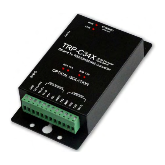
TRP-C34X
32 Bit Ethernet to 1 RS232 and 1 RS422/485 Optical
Isolated Converter
User's Manual
Printed Nov. 2012 Rev 1.1
Trycom Technology Co., Ltd
Tel: 886-3-3503351, Fax: 886-3-3503352
Web: www.trycom.com.tw
Copyright
Copyright Notice: The information in this manual is subject to change without prior notice in order to improve
reliability, design and function and dosed not represent a commitment on the part of the manufacturer. No part of
this manual may be reproduced, copied, or transmitted in any form without the prior written permission of
manufacturer. Acknowledgment Products mentioned in this manual are mentioned for identification purpose only.
Products manes appearing in this manual may or may not be registered trademarks or copyright of their respective
companies.
Advertisement

Related Manuals for Trycom Technology TRP-C34X


Summary of Contents for Trycom Technology TRP-C34X
- Page 1 32 Bit Ethernet to 1 RS232 and 1 RS422/485 Optical Isolated Converter User’s Manual Printed Nov. 2012 Rev 1.1 Trycom Technology Co., Ltd Tel: 886-3-3503351, Fax: 886-3-3503352 Web: www.trycom.com.tw Copyright Copyright Notice: The information in this manual is subject to change without prior notice in order to improve reliability, design and function and dosed not represent a commitment on the part of the manufacturer.
- Page 2 The driver establishes a transparent connection between host and serial device by mapping the IP: Port Number of the TRP-C34X’s Serial Port to a local COM Port on the host computer. The important point is that Real COM Mode allows users to continue using RS-232/422/485 serial communications software like HyperTerminal and similar applications.
- Page 3 Features Accessible Imps List to add or remove “legal” remote host IP Addresses to prevent unauthorized access to TRP-C34X. Features Auto IP Address Report to periodically report the IP Address of TRP-C34X to the assigned Host on Network. ...
-
Page 4: Hardware Description
Power Input Voltage: DC +10V to +30V. LAN: Auto-MDIX, 10/100 Mbps Auto-detecting. RS-232: TXD, RXD, RTS, CTS, ISO GND. RS-422: TX+, TX-, RX+, RX-, ISO GND. RS-485: Data +, Data –, ISO GND. Data Rate: 75~921Kbps. Parity: none, even, odd. - Page 5 Notice: User can only choose either external DC-Jack or Screw terminal DC input. Do not use DC-Jack and screw terminal DC input simultaneously. 2-2. LED indicators. PWR LED: Blinking: Not Ready. ON: TRP-C34X Ready . LINK LED: Ethernet cable connection and data active. TX/RX LED: COMA: RS422/485 Transiting/Receiving Indicator. COMB: RS232 Transiting/Receiving Indicator.
- Page 6 IP setting:...
- Page 7 STEP2: Connect TRP-C34X with Ethernet port by RJ45 cable. If the cable is properly connected the “LINK” LED will light up. *The TRP-C34X Supports Auto-MDIX, A straight-through or crossover RJ45 cable can be used to make a connection directly to the HUB/Router/PC LAN port.
- Page 8 3-3. RS232 Wiring. Refer to the Pin out table for connections. 4. How to configure TRP-C34X. There are 3 ways to access the TRP-C34X. a. Serial Server Admin Utility.
- Page 9 b. WEB Server. c. Telnet.
- Page 10 When Installation is completed the wizard creates a Serial Server Admin Utility shortcut on the Desktop as shown below. Double Click on the Serial Server Admin Utility then Right click on the main window or go to Server Manager in Menu Bar and select Search Devices to find the TRP-C34X on the network.
- Page 11 By default all the devices searched are locked and can be seen under the status column of the Server Manager Window in order to protect from unauthorized configuration changes. In order to configure the device, it has to be Unlocked first. Unlock password: trycom After the device has been Unlocked, the device can be configured for all Network, Serial, Operating settings.
- Page 12 On Basic page, check the Modify check Box to change any of the Configuration details. IP Setting:...
- Page 13 On IP Settings Page, click the modify box first, you can modify all the Network parameter a. IP address b. Net Mask c. Gateway d. Click the IP Configuration drop-down box, to modify the parameter Static/DHCP/BOOTP. e. DNS Server 1: When the user wants to visit a particular website, the computer asks the Domain Name System (DNS) Server for the website’s correct IP address, and the...
- Page 14 Contact: The SNMP contact information usually includes an emergency contact name and telephone or pager or Mobile number. Location: This string is usually set to the street address where the TRP-C34X is physically located. Port Settings Page On the Port Settings page of the Server Manager dialog displays all the serial ports, present on the Serial Server model of the selected device.
- Page 15 Click the checkbox “Apply Port Alias to all selected ports” to apply same port alias to all selected ports. Maximum length of Port alias is 5 characters. Click the specific drop-down box or click the check box to modify the serial port settings viz., Baud Rate / Parity / Data Bits / Stop Bits / Flow control / Interface.
- Page 16 Key in the TCP Alive Check Timeout to set the timeout for TCP Alive time. The Default setting is 7 min. TRP-C34X automatically closes TCP connection if there is no TCP activity for the given time. After the connection is closed, TRP-C34X starts listening for another REAL COM driver’s...
- Page 17 TCP Server Mode a. Local TCP Port: The TCP Port of TRP-C34X that uses to listen to the requests coming from Host Computers on Network in order to establish connection. The Host Computers should contact this Port in order to establish connection with the TRP-C34X.
- Page 18 Destination IP address 1 / 2 / 3 / 4 Accessible IP’s Page Accessible IP settings allow you to add or remove “legal” remote host IP address to prevent unauthorized access to TRP-C34X. Hosts that are included in this list can only access the TRP- C34X on the network.
- Page 19 On “Accessible IP’s” page , click the modify box to activate the parameter, Click on settings button to enter the IP Address and Net Mask of remote host that control the TRP-C34X . You can allow one of the following cases by setting the parameter.
- Page 20 On Auto warning page under E-mail and SNMP Trap Setting Tab, click the modify box to activate the parameter. a. On Mail server frame, input the IP Address or Domain Name of the Mail server. b. Input the From E-mail Address. c.
- Page 21 On Auto warning page, under Event Tab, click the Modify box to activate the parameter, and click the checkbox to set the Events for which Auto warnings are to be sent. To get Auto Warning E-Mails: i) Give the Mail Server IP address & authentication if required. ii) Give from ID &...
- Page 22 Network management becomes difficult when TRP-C34X is forced into DHCP. Any IP changes due to DHCP in TRP-C34X are reported to the assigned Host on the Network. On IP address Report, click the modify box to activate the parameter, and set the IP address, Port number and time period to Auto report to host.
- Page 23 Default Password is “trycom”. 4-3. Telnet. TRP-C34X implements a Telnet Server and can be invoked by making a Telnet from remote PC. In the “Basic Settings” page of “Windows Configuration Utility”, if the ‘Enable Telnet Console’ check box is enabled we can use the Telnet Console to modify the device parameters.
- Page 24 5. Application. 5-1. Real COM Mode. TRP-C34X Basic 2 Real COM Port installs. Example: Step1: Connect PC-----RJ45-----TRP-C34X-----RS232/422/485 Device. Step2: Run “Serial Server Admin Utility” and Right Click on the selected device and click on configure to go to Configuration menu.
- Page 25 Step4: Select “Port Mapping” then right clicks “Add Device”. Step5: The Port Mapping will show below.
- Page 26 Step7: Right Click select “Apply Change”.
- Page 27 Step7: The TRP-C34X Real COM Mode setting OK. *Notice: No matter how to change “Add device” or “Remove Device”, its need to be run “Apply change” for save COM Port configuration. Step8: plug in RS232 LOOP back connector.
- Page 28 Step9: RUN “Demo.exe” and select “setting”. Step10: Select “Action” then clicks “Connect”. Step 11. User also test RS422 loop back, Please same above step. *Demo setting “RTS/CTS” item need to Disable for test RS422. 5-2. TCP Server Mode.
- Page 29 Example: Step1: Connect Host PC 1~8-----Ethernet-----TRP-C34X-----PC . Step2: Run “Serial Server Admin Utility” and Right Click on the selected device and click on configure to go to Configuration menu. Step3: Be sure “IP Setting”,” Port Setting” and “Operating Mode” is correct.
- Page 30 Step5. Connect PC COM Port link TRP-C34X COMA~COMB. Step6. RUN “Demo.exe” and select correct baud-rate and data format. Step7. RUN “Telnet.exe” and input IP and Port. 5-3. Paired Mode. Example:...
- Page 31 Step1: Run “Serial Server Admin Utility” and Right Click on the selected device and click on configure to go to Configuration menu. Step3: Be sure “IP Setting”,” Port Setting” and “Operating Mode” is correct. Step4: TRP-C34X Client setting, Select “Operating Mode” and then double click Port1~Port2 item same below. a. Port 1 Setting.
- Page 32 Port 2 Setting. Step5: TRP-C34X Server setting, Select “Operating Mode” and then double click Port1~Port2 item same below.
- Page 33 a. Port 1 Setting. b. Port 2 Setting.
- Page 34 Step6: Keep the TRP-C34X Server in LAN. Also keep the Client PC in LAN. Step7: Power ON the TRP-C34X Server and wait till it completely boots PWR LED ON first. Step8: Power ON the TRP-C34X Client and wait till it completely boots PWR LED ON.
- Page 35 Step9: Select “Action” then clicks “Connect”. 6. TRP-C34X Application Diagram.
Need help?
Do you have a question about the TRP-C34X and is the answer not in the manual?
Questions and answers