Advertisement
Quick Links
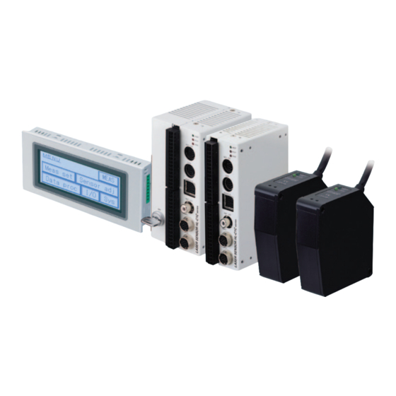
INSTRUCTION MANUAL
Ultra High-speed Laser Displacement Sensor (CCD Style)
HL-C1 series
Bornier : IP 20
ME-HLC1 No.0296-00
A UDIN Composants & systèmes d'automatisme
Siège :7 bis rue de Tinqueux - 51100 Reims - France - Tel : 03.26.04.20.21 - Fax : 03.26.04.28.20
Agence Nord : 66 rue J.Baptiste Lebas - 59910 Bondues - France Tel : 03.20.27.99.84 - Fax : 03.20.27.99.85
Web : http://www.audin.fr - Email : info@audin.fr
Advertisement

Related Manuals for Sunx HL-C1 Series


Summary of Contents for Sunx HL-C1 Series
- Page 1 INSTRUCTION MANUAL Ultra High-speed Laser Displacement Sensor (CCD Style) HL-C1 series Bornier : IP 20 ME-HLC1 No.0296-00 A UDIN Composants & systèmes d'automatisme Siège :7 bis rue de Tinqueux - 51100 Reims - France - Tel : 03.26.04.20.21 - Fax : 03.26.04.28.20 Agence Nord : 66 rue J.Baptiste Lebas - 59910 Bondues - France Tel : 03.20.27.99.84 - Fax : 03.20.27.99.85...
- Page 2 Contents Contents Cautions Concerning Safety Cautions Concerning Handling of Laser Light Correct Handling Method Warranty CHAPTER 1 NAMES AND FUNCTIONS OF PARTS 1-1 Controller 1-2 Sensor Head 1-3 Compact Console CHAPTER 2 INSTALLATION 2-1 System Configuration 2-2 Installation Environment and Installation Space 2-3 Mounting the Controller 2-4 Mounting the Sensor Head 2-5 Mounting the Compact Console...
- Page 3 Contents 5-2-10 High Pass Filter 5-13 5-2-11 Upper and Lower Limit and Hysteresis Settings 5-14 5-2-12 Judgment Output Selection 5-17 5-2-13 Output Mode 5-18 5-2-14 Analog Output Setting 5-19 5-2-15 Analog Output During Alarm 5-21 5-2-16 Input Selection 5-22 Input Operation 5-22 LD Emission 5-22...
- Page 4 Cautions Concerning Safety Indicates the possibility that death or serious injury to Warning the user could result if a handling error is made. If this product is used in applications where this bodily injury or massive extended damage could develop, incorporate safety countermeasures such as a double safety mechanism.
- Page 5 4) The sensor head in this device is not equipped with a function that stops laser radiation automatically when it is disassembled, so be sure to contact SUNX if it breaks down. There is danger of laser radiation occurring if the head is disassembled for repairs, etc.
- Page 6 Laser Emission Indicator Measuring Range Indicator Warning Label...
- Page 7 Correct Handling Method Be careful of the following points when installing and using this product. 1. About Warming Up Time - Allow at least 30 minutes of warming up time after turning on the power to assure optimum performance. 2. About the Use Environment Ambient Temperature, Humidity, Luminance - Use this product in the temperature specification range (sensor head: 0 to +45°C, controller: 0 to +50°C, compact console: 0 to +40°C).
- Page 8 - Set the sensor head so that stray light such as sunlight or light with the same wavelength, etc. does not enter the light receptor. If an extraordinary accuracy is necessary, install a light shielding plate or the like at the sensor. - The sensor head is a waterproof device, but this does not mean that it can be mounted underwater or in places where rain falls.
- Page 9 4. Insulation Resistance and Voltage Resistance - Do not perform insulation resistance and voltage resistance tests between the power supply, input and output signals and the metal parts of the controller. 5. Power Supply - Select a power supply with a ripple of 0.5V or less (P-P) and a current capacity of 2A or more.
- Page 10 7. Installation Controller - Install the controller unit in accordance with "Considerations Concerning Heat Radiation" on page 2-2, assuring plenty of space around the unit. If it is installed in a manner that is not in accordance with instructions, it could cause malfunction due to the rise in temperature, etc.
- Page 11 Extent of Warranty If this product should break down or if a defect becomes apparent which is the responsibility of SUNX during the warranty period, SUNX will promptly provide a replacement product or the necessary replacement parts, or will replace or repair the defect parts free of charge at the place where the product was purchased or at the place where delivery was made.
- Page 12 CHAPTER 1 NAMES AND FUNCTIONS OF PARTS...
- Page 13 CHAPTER 1 NAMES AND FUNCTIONS OF PARTS 1-1 Controller (1) Laser Emission Indicator (Green) (2) BRIGHT Indicator (Red) (11) (3) DARK Indicator (Red) (4) Cannot be used. (5) COM. Port (6) Connector for Compact Console (12) Connection (7) Cannot be used. (8) Sensor Head 1 Connector (9) Sensor Head 2 Connector (10)
- Page 14 CHAPTER 1 NAMES AND FUNCTIONS OF PARTS (1) Laser Emission Indicator (Green) Lights up during laser emission from sensor head 1 or sensor head 2, or immediately before laser emission. (2) BRIGHT Indicator (Red) Lights up when the amount of light emitted by sensor head 1 or sensor head 2 is excessive, making measurement impossible.
- Page 15 CHAPTER 1 NAMES AND FUNCTIONS OF PARTS 1-2 Sensor Head (1) Laser Emission Indicator (2) Measuring Range Indicator (3) Warning Label...
- Page 16 CHAPTER 1 NAMES AND FUNCTIONS OF PARTS (1) Laser Emission Indicator (Green) Lights up during laser emission or immediately before laser emission. (2) Measuring Range Indicator (Yellow) Blinks when within the measuring range and lights up when near the center of the measuring range.
- Page 17 CHAPTER 1 NAMES AND FUNCTIONS OF PARTS 1-3 Compact Console [Front] (1) Liquid Crystal Panel (Touch Panel) (2) Front Protective Sheet [Rear] (3) Power Supply Terminal (4) COM. Port (5) (TOOL Port) (6) (Operating Mode Setting Switch) (7) Waterproof Packing...
- Page 18 CHAPTER 1 NAMES AND FUNCTIONS OF PARTS (1) Liquid Crystal Panel (Touch Panel) Measuring data and the various setting values are displayed in this panel. The setting can also be changed and data input by touching the panel. (2) Front Protective Sheet A sheet is affixed to the liquid crystal panel when the sensor is shipped to protect it and keep it from getting dirty.
- Page 19 CHAPTER 1 NAMES AND FUNCTIONS OF PARTS MEMO...
- Page 20 CHAPTER 2 INSTALLATION...
- Page 21 CHAPTER 2 INSTALLATION 2-1 System Configuration RS-232C Cable 3m Made by Matsushita Electric Works, Ltd. ANM81103 Controller Compact Console Connection Cable 2m (supplied with the compact console) Sensor Head Extension Cable 2m, 5m, 10m For a system with only one sensor head connected to the controller, connect to the sensor head 1 (HEAD 1) connector.
- Page 22 CHAPTER 2 INSTALLATION 2-2 Installation Environment and Installation Space Avoid installation in the following places: - Places where the ambient temperature exceeds the specification range (sensor head: 0 to +45°C, controller: 0 to +50°C, compact console: 0 to +40°C). - The relative humidity exceeds the range of 35 to 85% relative humidity. - The luminance at the light receptor exceeds 3,000 lx (incandescent lamp).
- Page 23 CHAPTER 2 INSTALLATION Installation Space - Mount the controller so that it is separated from surrounding ducts and other devices by 50mm or more to enable replacement and wiring, etc. - If a panel door or other device is placed in front of the controller unit, separate it from the controller by 100mm or more to avoid the influence of radiation noise or heat generation.
- Page 24 CHAPTER 2 INSTALLATION 2-4 Mounting the Sensor Head Mounting the Sensor Head - Fasten the sensor securely with M5 screws, using the 2 holes in the corners of the sensor head. Contain the tightening torque to within 1.2N m. - Mount the sensor head so that it is approximately 85mm from the object to be measured. - Mount the sensor head so that its front is normal to the measured object.
- Page 25 CHAPTER 2 INSTALLATION Sensor Head Mounting Direction Mount the sensor head in the orientation shown below to obtain accurate measurements. - Rotating objects - Objects with level differences or grooves - Objects with great changes in color...
- Page 26 CHAPTER 2 INSTALLATION Mutual Interference If two or more sensor heads are mounted close to each other, there will be no mutual interference if the neighboring sensor's laser spot is outside the shaded portion shown in the figure below. Mount the other sensor heads so that their laser spot does not enter the shaded area. (Unit : mm)
- Page 27 CHAPTER 2 INSTALLATION Output Characteristics and Measuring Range Indicator Lights Measuring Range Indicator Blinks Blinks Beam Diameter (mm) Measuring Center Distance Measuring Range Displacement Output Distance (mm) Open Alarm Output (N.C.) Closed With the analog output set at 20mm (at 5V) and -20mm (at -5V)
- Page 28 CHAPTER 2 INSTALLATION 2-5 Mounting the Compact Console Mount the installation plate using the enclosed mounting fittings (4 Nos.) and installation screws (4 Nos.). (1) Insert the compact console unit in the mounting plate. (2) Fit the mounting plate in the groove in the compact console unit, then tighten the screws, fastening the compact console to the mounting plate.
- Page 29 CHAPTER 2 INSTALLATION Wiring the Power Supply - Connect the power cable at the terminals provided on the back of the main body. - Use twisted wires for the power supply lines to minimize the effect of noise. - Use an insulated type power supply with a built-in protective circuit for the power supply to protect against abnormal voltages from the power line.
- Page 30 CHAPTER 3 INPUT AND OUTPUT TERMINAL BLOCKS...
- Page 31 CHAPTER 3 INPUT AND OUTPUT TERMINAL BLOCKS 3-1 Wiring Terminal Blocks Output Terminal Block Input / Power Supply Terminal Block Terminal Blocks The adopted terminal block is removable from the controller and can be tightened with screws. Use the following tools and cables. Maker Model Enclosed Terminal Block Socket...
- Page 32 CHAPTER 3 INPUT AND OUTPUT TERMINAL BLOCKS Wiring Method 1. Strip the insulation off 2. Insert the wire in the 3. If two or more wires the end of the wire. terminal block until it are inserted into the hits the back side, then s a m e t e r m i n a l , t w i s t fa s t e n it in place by the wires together, then...
- Page 33 CHAPTER 3 INPUT AND OUTPUT TERMINAL BLOCKS 3-2 Output Terminals Terminal Layout Symbol Content A L 1 Alarm Output (Sensor Head 1) Judgment Output 1 (Sensor Head 1) Judgment Output 2 (Sensor Head 1) External Insulated GND A L 2 Alarm Output (Sensor Head 2) Judgment Output 1 (Sensor Head 2) Judgment Output 2 (Sensor Head 2)
- Page 34 CHAPTER 3 INPUT AND OUTPUT TERMINAL BLOCKS Output Circuit Alarm Output, Judgment Output Load 30V DC max. Laser Sensor Analog Output Circuit -10.9 to +10.9V Notes: 1) Be careful not to create a short circuit between analog output terminals or apply voltage to them. 0 to 29.5mA 2) Use shielded wires for analog outputs.
- Page 35 CHAPTER 3 INPUT AND OUTPUT TERMINAL BLOCKS 3-3 Input Terminals Symbol Content Timing Input (Sensor Head 1) Zero Set ON Input (Sensor Head 1) Zero Set OFF Input (Sensor Head 1) External Insulated GND Timing Input (Sensor Head 2) Zero Set ON Input (Sensor Head 2) Zero Set OFF Input (Sensor Head 2) External Insulated GND Not Used...
- Page 36 CHAPTER 3 INPUT AND OUTPUT TERMINAL BLOCKS 3-4 Wiring Power Supply Terminal Layout - Use the + terminal and - terminal on the input terminal block to wire the power supply, supplying 24V DC. - Use twisted wires for the power supply to minimize the effect of noise. Rated Voltage 24V DC Permissible Voltage...
- Page 37 CHAPTER 3 INPUT AND OUTPUT TERMINAL BLOCKS Give consideration to the power supply sequence. - Give consideration to a power supply sequence in which the controller's power supply is turned Off before the input and output power supplies. - If the input and output power supplies are turned Off before the controller power supply, the controller will detect a change in the input signal level and may malfunction as a result.
- Page 38 CHAPTER 4 MEASURING METHODS...
- Page 39 CHAPTER 4 MEASURING METHODS 4-1 Basic Operation of the Compact Console Outline of the Contents of Each Screen MENU Screen Screen Name Screen Contents This is the main menu screen. All the screens can be accessed via MENU this screen. This displays the measurement values.
- Page 40 CHAPTER 4 MEASURING METHODS Selecting from the items Here we explain how to select the item having the choices such as sampling period and average number of samples. Setting Value If sampling period is selected in the measurement setting screen The value shown in the frame is the current setting value.
- Page 42 Flow of Each Screen Measurement Sensor Adjustment System Input/output Data Processing Measurement Settings...
- Page 44 CHAPTER 4 MEASURING METHODS 4-2 Measuring Height Here we explain measurement of the difference in height of the measured object with respect to a reference surface. Here, the basic operation method is explained with the method of measuring the surface shape of a plate used as an example. Measurement Waveform Procedure 1.
- Page 45 CHAPTER 4 MEASURING METHODS 4. Perform Zero Setting MENU Screen Touch the button on the compact console's measurement display screen and switch to the sub screen one level down. Touch t o p e r f o r m z e r o Measurement Display Screen setting.
- Page 46 CHAPTER 4 MEASURING METHODS 4-3 Measuring Thickness Here, we explain concerning measurement of the changes in thickness of the measurement object with respect to the reference thickness. The example here shows the basic operation method for measuring the thickness of a plate using two sensor heads. Measuring Waveform Procedure 1.
- Page 47 CHAPTER 4 MEASURING METHODS - Change over between the sensor head 1 (H1) and sensor head 2 (H2) display in the measurement display screen of the compact console. - If "add/subtract" is selected for the head operation, change to "independent" while referring to page MENU Screen 5-8.
- Page 48 CHAPTER 5 FUNCTION ITEM...
- Page 49 CHAPTER 5 Function Item 5-1 List of Functions Page Displays the measurement values. Changes the Measurement hold mode. Allows zero setting, timing and display hold inputs. Changes the hold mode between NORM. / P-P / Hold Mode PEAK and VALLEY. Sets the measurement value and analog output Measurement Zero Set...
- Page 50 CHAPTER 5 FUNCTION ITEM 5-2 Explanation of Functions 5-2-1 Hold Mode This device has 4 hold modes, and the measurement results in the set mode are displayed / output. Hold Mode Function Outputs the amount of displacement from the measurement center distance in NORM.
- Page 51 CHAPTER 5 FUNCTION ITEM Setting the Hold Mode 1. Display the measurement display screen. When Measurement] is touched in the MENU MENU Screen Screen and the measurement display screen is displayed, the currently set hold mode is displayed in the hold mode key area.
- Page 52 CHAPTER 5 FUNCTION ITEM 5-2-2 Zero Set The amount of displacement is displayed in reference to the center of measurement of the sensor head during regular operation. After a zero setting input is added, the amount of displacement in reference to the current position is displayed. Therefore the measurement value and analog output at the timing of zero setting are forcibly reset to zero.
- Page 53 CHAPTER 5 FUNCTION ITEM 5-2-3 Timing The judgment output (O1 and O2) immediately before the mode selection, measurement value and analog output are held in the timing input mode. Laser emission can be halted or continued according to a setting. Add the input in other than the measurement or judgment state to eliminate unnecessary output changes or laser radiation.
- Page 54 CHAPTER 5 FUNCTION ITEM 5-2-4 Display Hold Only the measurement value displayed on the compact console is held. Use this function to read a momentary measurement value. 1. From the measurement display screen, touch MENU Screen and display the sub screen. Touch from the MENU screen.
- Page 55 CHAPTER 5 FUNCTION ITEM 5-2-5 Sampling Period In cases where work pieces with a low reflected light amount, such as black rubber, are measured, stable measurements can be taken by extending the sampling period and enabling a sufficient amount of light to be picked up by the sensor. If the sampling period is short and not enough light can be picked up, the sensor enters the alarm state, so switch the sampling period to a longer duration setting.
- Page 56 CHAPTER 5 FUNCTION ITEM 5-2-6 Sensor Head Operation 2 sensor heads can be used to measure independently, or they can be combined to take thickness measurements or level difference measurements, etc., and calculations made to determine the measurement results. The measurement value display and the analog output and judgment output can also be switched.
- Page 57 CHAPTER 5 FUNCTION ITEM 5-2-7 Calculation Formulas L1 + K1A This is the normal output state, with the near side output as a negative value. L2 + K2B This is selected to output the height of the measurement object as a positive L1 - K1A value, etc.
- Page 58 CHAPTER 5 FUNCTION ITEM 3. Select the calculation formula. Independent Calculation Screen Add/subtract Screen - Touch the calculation formula key and display the calculation formula to be selected. - Each time the key is touched, the display changes as shown below. Independent H1: L1+K1A L1-K1A...
- Page 59 CHAPTER 5 FUNCTION ITEM 5-2-8 Average Number of Samples The measurement result can be smoothed so that stable measurement values are obtained. The number of samples can be set in 16 steps between OFF and 32,768 times. MENU Screen 1. Touch Touching in the MENU screen and displaying the average screen displays the currently set average...
- Page 60 CHAPTER 5 FUNCTION ITEM 5-2-9 Low Pass Filter If, for example, machining state of a metal surface generates noise and hinders an accurate measurement, this setting can reduce its influence and enable a stable displacement measurement. 1. Touch MENU Screen Touch in the MENU screen.
- Page 61 CHAPTER 5 FUNCTION ITEM 5-2-10 High Pass Filter If joints or grooves are being measured in the midst of great changes such as runout or inclination in an eccentric rotating object etc., this setting minimizes the effects of gradual changes and makes it possible to detect the joints or grooves.
- Page 62 CHAPTER 5 FUNCTION ITEM 5-2-11 Upper and Lower Limit and Hysteresis Settings Upper and Lower Limit Settings Set the upper and lower limits of the judgment output issued at O1 and O2. The upper and lower limit values can be set for each sensor head. MENU Screen 1.
- Page 63 CHAPTER 5 FUNCTION ITEM 4. Set the upper limit value for sensor head 2. Lower Limit Value Screen In the case of independent operation, touch again. Set the upper limit value in the upper limit value screen for sensor head 2. In the case of add/subtract operation as well, setting the upper and lower limit setting values for sensor head 2 causes execution of the judgment operation.
- Page 64 CHAPTER 5 FUNCTION ITEM 3. Set the lower limit hysteresis. Lower limit hysteresis Screen Touch in the upper limit hysteresis screen to change to the lower limit hysteresis screen. A keyboard is displayed so that the current setting and value can be entered. Enter the hysteresis for the lower limit value of sensor head 1.
- Page 65 CHAPTER 5 FUNCTION ITEM 5-2-12 Judgment Output Selection The judgment output (O1 and O2) can be selected from the four types listed in the table below. Display Logical Output and Judgment (HIGH) Judgment :Upper Limit Value (HIGH) LOW INRANGE HIGH HIGH Output RANGE...
- Page 66 CHAPTER 5 FUNCTION ITEM 5-2-13 Output Mode This makes it possible to distinguish whether the amount of light at each sensor head is excessive or insufficient when measurement is impossible. This is used mainly during installation and when trouble occurs etc., and is used as supplementary information when searching for the cause of being unable to take measurements.
- Page 67 CHAPTER 5 FUNCTION ITEM 5-2-14 Analog Output Setting This function causes the output to correspond to the desired measurement value at an analog output of+5V (20mA) and at -5V (4mA). It can be used for scaling of the analog output or for making the output greater or smaller, etc.
- Page 68 CHAPTER 5 FUNCTION ITEM 6. Set the measurement value corresponding to +5V for sensor head 2. Touch again in the case of independent operation. Set the measurement value that you would like to correspond to +5V (20mA) for sensor head 2. 7.
- Page 69 CHAPTER 5 FUNCTION ITEM 5-2-15 Analog Output During Alarm You can switch between the data having been output immediately before and a fixed value as an analog output issued when measurement is disabled (with an alarm output) due to an excessive or poor amount of light or deviation from the range.
- Page 70 CHAPTER 5 FUNCTION ITEM 5-2-16 Input Selection Input Operation The timing signal at the input terminal functions as an input upon a short circuit by default setting. Use this function to activate the input upon an open circuit. MENU Screen 1.
- Page 71 CHAPTER 5 FUNCTION ITEM Two-sensor Head Input Mode If the 2 sensor heads are operating independently, ordinarily, the timing and zero set inputs are input independently for each sensor head, but even during independent operation, batch input is set in cases where input of these values to the 2 sensor heads simultaneously is desired for measuring the same work piece, etc.
- Page 72 CHAPTER 5 FUNCTION ITEM 5-2-17 Calibration In some cases, deviations in the measurement value occur due to the color, material and surface conditions of the measurement object. Correction for such deviations is called calibration. In calibration, span and shift are set for each sensor head. There are 2 ways to set these values.
- Page 73 CHAPTER 5 FUNCTION ITEM 4. Place the work piece in the measuring position, then touch Place the work piece in the measuring position or move the work piece that is to be moved in the opposite direction and measure the work's height or measure the work piece's movement.
- Page 74 CHAPTER 5 FUNCTION ITEM Direct Input of Span and Shift If you know that calibration values (span, shift) for the same measurement object have already been used, those values can be input directly. MENU Screen 1. Display the Calibration screen. Touch in the MENU screen, then in the sensor adjustment screen, touch...
- Page 75 CHAPTER 5 FUNCTION ITEM About Span and Shift in Calibration and Coefficient and Offset in Calculation Formulas The span and shift in calibration can be set and the coefficient K and offset L in the calculation formulas can be set independently. The calibration span is a correction value to match the measurement value's deviation with the actual displacement.
- Page 76 CHAPTER 5 FUNCTION ITEM 5-2-18 Amount of Light Received This displays the peak amount of light received at the measuring point. 1. Display the sensor adjustment screen. Touch in the MENU screen and display the MENU Screen sensor adjustment screen. 2.
- Page 77 CHAPTER 5 FUNCTION ITEM 5-2-19 Save All setting data except for the timing input mode and display hold mode is saved. When the power is turned on, the settings are those having been saved last time. If settings are changed and the new data is not saved, changes are abandoned when the power is turned off. 1.
- Page 78 CHAPTER 5 FUNCTION ITEM 5-2-20 Initialization This erases all the settings and restores the initial settings set at factory. Setting contents are not saved even by initialization, so if you would like to retain the initialized state after the power is turned off, execute "Save". 1.
- Page 79 CHAPTER 5 FUNCTION ITEM List of Default Values Page Function Item Default Value Mentioned Hold Mode NORM. Zero Set Measurement Timing Display Hold Sampling Period 144 s Sensor Head Operation Independent Independent Calculation Formula L1+K1A, L2+K2B Measurement Add/subtract Calculation Formula L+K(A+B) Setting Independent - Add/subtract Calculation...
- Page 80 CHAPTER 5 FUNCTION ITEM 5-2-21 Lock Data setting and modification at the compact console can be prohibited to protect the data from inadvertent operation of the compact console. When the data is locked, all operations other than screen display change and unlocking are disabled. However, saving can be executed. To validate the key lock setting even after the power is turned off, execute saving.
- Page 81 CHAPTER 5 FUNCTION ITEM 5-2-22 Version This displays the controller and compact console version. 1. Display the system screen. MENU Screen Touch in the MENU screen and display the system screen. 2. Display the version screen. is touched in the system screen, the screen changes to the controller version screen.
- Page 82 CHAPTER 6 RS-232C CONTROL...
- Page 83 CHAPTER 6 RS-232C CONTROL 6-1 Communications Specifications Transmission Speed 115,200 bps Communications Full Duplex Method Synchronization Asynchronous Method Transmission Code ASCII Data Length 8 bits Parity Check None Stop Bit Length 1 bit End Code CR (0DH) To omit BCC calculation, enter " "...
- Page 84 CHAPTER 6 RS-232C CONTROL Wiring Example PC-AT Compatible Computer Pin No. Signal Name Laser Sensor Pin No. Signal Name Cover Shield Cover Shield 3-meter RS -232C Cable: Use the ANM81103 <made by Matsushita Electric Works, Ltd.> Set the Communications Specifications. - Set the communications specifications for the controller side.
- Page 85 CHAPTER 6 RS-232C CONTROL Sending and Receiving Data Description is made here to explain the method of transmission of commands from the PC to the controller for giving, changing, or monitoring various parameters or reading measurement values. 1. Send a command from the PC to the controller. 2.
- Page 86 CHAPTER 6 RS-232C CONTROL Select Sensor Head The specification for select sensor head differs depending on the setting contents of the sensor head's operation. Sensor Head Operation Select Sensor Head Independent Operation Add/subtract Operation Add/subtract Sensor Head 1 Calculation Sensor Head 2 Sensor Head 2 Sensor Head not specified.
- Page 87 CHAPTER 6 RS-232C CONTROL 6-2 List of Commands Selected Setting Item Command Sensor Content Page Code Head Read Measurement Read once. 1 Read light amount Read once. received NORM. Measure- Hold Mode RHM WHM PEAK ment VALLEY Zero Set Timing 1,000µs 498µs 332µs...
- Page 88 CHAPTER 6 RS-232C CONTROL Selected Setting Item Command Content Page Sensor Code Head OFF, 2, 4, 8, 16, 32, 64, 128, 256, 512, 1024, Average 6-11 2048, 4096, 8192, Data 16384, 32768 times Processing OFF, 10, 20, 50, 100, Low Pass Filter 200, 500, 1,000, 6-12 High Pass Filter RHP...
- Page 89 CHAPTER 6 RS-232C CONTROL 6-3 Explanation of Commands The commands are described here. For detail functions, refer to Chapter 5. (In the send/receive data example, BCC is omitted.) 6-3-1 Read Measurement, Read Light Amount Received Command Code Function Content Read Read Read 1 time.
- Page 90 CHAPTER 6 RS-232C CONTROL 6-3-3 Zero Set, Timing Command Code E # R Function Setting Content Read Command Code Select Head Zero Set Timing Command Code Setting Code Select Head Example (1) Read the setting contents (it is shown with BCC omitted). If sensor head 1 is in the zero set state.
- Page 91 CHAPTER 6 RS-232C CONTROL 6-3-5 Sensor Head Operation E # R H F 3 Command Code Function Setting Content Command Code Read Select Head Independent Sensor Head operation # W H F 3 Operation Add/subtract Command Code operation Setting Code Select Head Example (1) Read the setting contents (it is shown with BCC omitted).
- Page 92 CHAPTER 6 RS-232C CONTROL 6-3-7 Calculation Offset, Calculation Coefficient Command Code Function Setting Code Setting Value Range Read Independent 999.9999mm Calculation Code + Number (Zero Suppress) Offset Independent Calculation 0.0001 to 99.9999 Number (Zero Suppress) Coefficient Add/subtract 999.9999mm Calculation Code + Number (Zero Suppress) Offset Add/subtract Calculation...
- Page 93 CHAPTER 6 RS-232C CONTROL 6-3-8 Calibration: Span, Shift Command Setting Value Function Code Setting Code Range Read Span 0.9000 to 1.1000 20.0000mm Shift Code + Number (Zero Suppress) E # R Command Code Command Code Setting Select Head Select Head Code Example (1) Read the setting contents (it is shown with BCC omitted).
- Page 94 CHAPTER 6 RS-232C CONTROL E # R A V # W A V Command Code Command Code Select Head Setting Code Select Head (1) Read the setting contents (it is shown with BCC omitted). If the sensor head 1 average number of samples is 4,096 times. Respond Send % E E # R A V 1...
- Page 95 CHAPTER 6 RS-232C CONTROL 6-3-11 Upper Limit and Lower Limit Values and Hysteresis Command Code Setting Value Function Setting Code Range Read Upper Limit Value 999.9999mm Lower Limit Code + Number (Zero Suppress) Value Upper Limit Hysteresis 0.0000 to Lower Limit 2.0000mm Hysteresis E # R...
- Page 96 CHAPTER 6 RS-232C CONTROL 6-3-12 Analog Output Command Code Setting Value Function Setting Code Range Read Analog Output +5V 999.9999mm Code + Number Analog Output -5V (Zero Suppress) E # R A Command Code Command Code Setting Select Head Select Head Code Example (1) Read the setting contents (it is shown with BCC omitted).
- Page 97 CHAPTER 6 RS-232C CONTROL 6-3-14 Other Command Code Setting Function Content Code Read Analog output during Hold alarm Fixed Value +10.9V, 29.5mA Fixed Value -10.9V, 0mA Operation during a short circuit Timing Input Operation Operation during an open circuit Independent Input Input Mode Batch Input Normal...
- Page 98 CHAPTER 6 RS-232C CONTROL 6-3-15 System Function Command Code Command Code Save Initialize Example (1) Save the setting contents (internal memory) (it is shown with BCC omitted). Respond Send % E E # M M R $ M M R (2) Initialize the setting contents (it is shown wit BCC omitted).
- Page 99 CHAPTER 6 RS-232C CONTROL 6-4 List of Error Codes Error Type of Error Content Code A data error occurred during communications (framing Data Error error, parity error, BCC error). The receiving buffer of the controller has overflowed Overrun Error and no more data can be received. There was an error in the command symbol (there was no "#") there were too many or not enough digits in the setting figures, etc., so that the command format is...
- Page 100 CHAPTER 7 INSPECTION...
- Page 101 CHAPTER 7 INSPECTION 7-1 Inspection Inspect the laser sensor periodically to make sure of its performance and assure that it is used under the best possible conditions. Major Inspection Items - Check if the input and output terminal connections are loose or disconnected. - Check if there is any dirt or dust, or fingerprints, etc.
- Page 102 CHAPTER 8 TROUBLESHOOTING...
- Page 103 CHAPTER 8 TROUBLESHOOTING 8-1 Treatment Methods when Trouble Occurs Related Content of Trouble Cause Treatment Method Pages The connection cables are Check the connection condition of the - The compact console's not connected correctly. connection cables. display does not change. If the connectors and cables are - The compact console's There is a disconnection in...
- Page 104 CHAPTER 8 TROUBLESHOOTING 8-2 Lock - To prevent setting errors by inadvertent operation of the compact console, setting of the compact console and change operations can be prohibited. - Set the key lock and release the key lock with reference to page 5-32. - When setting the key lock, it becomes impossible to do any operations except change screen displays and release the key lock.
- Page 105 CHAPTER 8 TROUBLE SHOOTING MEMO...
- Page 106 CHAPTER 9 SPECIFICATIONS...
- Page 107 CHAPTER 9 SPECIFICATIONS 9-1 Sensor Head Model name HL-C108B-BK Measuring center distance 85mm Measuring range 20mm Visible Semiconductor Laser Light source (Wavelength: 685nm, 1 mW max., Class 2) Beam diameter ( Approx. 100 140 m Receiving element Linear Image Sensor Resolution Linearity 0.1% F.S.
- Page 108 CHAPTER 9 SPECIFICATIONS 9-2 Controller NPN Output Type Model name HL-C1C Supply voltage 24V DC 10% Incl. ripple 0.5V (P-P) When 2 sensors are connected: Approx. 550mA Current consumption When 1 sensor is connected: Approx. 430mA Sampling period 100 s, 144 s, 200 s, 255 s, 332 s, 498 s, 1,000 s Serial input/output RS-232C Thermal characteristics...
- Page 109 CHAPTER 9 SPECIFICATIONS Connection heads Maximum 2 sensor heads Setting / Data display Compact console (option) Shift 20.0000mm Calibration 0.9000 to 1.1000 Span Average number of OFF, 2 to 32,768 times (16 steps) samples ( High Pass: OFF, 10 to 2 ,000Hz (9 steps) Digital filters ( Low Pass: OFF, 10 to 2,000Hz (9 steps) L KA, L KB, L K (A B)
- Page 110 CHAPTER 9 SPECIFICATIONS 9-3 Compact Console Model HL-C1DP 24V DC ±10% incl. ripple 0.5V (P-P) Supply voltage Current consumption 200mA or less Display element STN monochrome LCD Display Back light Green LED Life of LCD Average 50,000 hours ( Touch Operation force 0.98N or less panel...
- Page 111 CHAPTER 9 SPECIFICATIONS MEMO...
- Page 112 CHAPTER 10 DIMENSIONS...
- Page 113 CHAPTER 10 DIMENSIONS 10-1 Sensor Head (Unit : mm) Light Receptor Light Emitter Extended Cable Model Name Length L (mm) HL-C1CCJ 2 2,000 HL-C1CCJ 5 5,000 HL-C1CCJ 10 10,000 10-1...
- Page 114 CHAPTER 10 DIMENSIONS 10-2 Controller (Unit : mm) 4-M3 Depth: 1.5 10-2...
- Page 115 CHAPTER 10 DIMENSIONS 10-3 Compact Console (Unit : mm) 2(Packing) Panel Cutting Method Appropriate Panel Thickness 1.0 mm to 6.0 mm 10-3...
- Page 117 SUNX Limited http://www.sunx.co.jp/ Head Office 2431-1 Ushiyama-Cho, Kasugai - shi, Aichi, 486-0901, Japan Phone: +81-(0)568-33-7211 FAX: +81-(0)568-33-2631 Overseas Sales Dept. PRINTED IN JAPAN Phone: +81-(0)568-33-7861 FAX: +81-(0)568-33-8591 ME-HLCI No.0296-00...
Need help?
Do you have a question about the HL-C1 Series and is the answer not in the manual?
Questions and answers