Advertisement
Quick Links
INSTRUCTION MANUAL
Head Separated Digital Pressure Sensor Controller
Pressure Sensor
DPC-100 Series
Thank you very much for using SUNX products. Please read this Instruc-
tion Manual carefully and thoroughly for the correct and optimum use of this
product. Kindly keep this manual in a convenient place for quick reference.
Never use this product in a device for personnel protection.
In case of using devices for personnel protection, use products which
meet laws and standards, such as OSHA, ANSI or IEC etc., for person-
nel protection applicable in each region or country.
The product for use inside Japan complies with Japanese Measurement
Laws. Avoid using the product for use outside Japan within Japan.
1
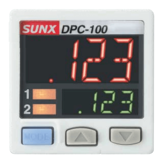
PART DESCRIPTION
Output 1 operation
indicator
Lights up when compara-
DPC-100
tive output 1 is ON
Output 2 operation
indicator
Lights up when compara-
tive output 2 is ON
Mode selection key
Notes: 1) Attach the unit switching label corresponds to the set pressure unit.
2) The product for use inside Japan can be set only to "MPa" or "kPa."
2
MOUNTING
The sensor mounting bracket (MS-DP1-6) is available as an option.
When mounting the sensor onto the sensor mounting bracket, etc., the
tightening torque should be 0.5N·m or less.
M3 (length 6mm) screws
with washers
(Accessory with MS-DP1-6)
Sensor mounting bracket
MS-DP1-6 (Optional)
The panel mounting bracket MS-DP1-2 (optional), as well as the front
cover MS-DP1-3 (optional) are also available.
For mounting of the panel mounting bracket, refer to the Instruction
Manual enclosed with MS-DP1-2.
CONNECTION OF PRESSURE SENSOR HEAD
3
This product can automatically recognize the connected pressure sensor head.
When replacing the pressure sensor head, the threshold value may be
Connection method
Insert the pressure sensor head cable
the pressure sensor head as shown in
Disconnection method
Pressing the release lever of the pres-
sure sensor head cable, pull out the
connector.
Note: Do not pull by holding the cable without pressing the release lever, as this can cause
cable break or connector break.
<Connector pin arrangement>
Connector pin No.
1
2
3
4
MJE-DPC100 No.0007-98V
Connector area for a power supply /
I-O cable
Unit display
(Notes)
Main display
Sub display
Set value
DOWN key
Connector area for a pressure
Set value UP key
sensor head
Pressure sensor
head cable
Release lever
Connector area of the pressure sensor
head cable
e-con: 1473562-4
[Tyco Electronics AMP K.K.]
Terminal name
1
Sensor head supply voltage
2
Analogue input
3
0V
4
Model discrimination signal
4
WIRING
Connection method
I n s e r t t h e c a b l e w i t h c o n n e c t o r
CN-66A-C
tor area for a power supply / I-O cable
Disconnection method
Pressing the release lever of the cable
with connector, pull out the connector.
Note: Do not pull by holding the cable without pressing the release lever, as this can cause cable
break or connector break.
<Connector pin arrangement>
Connector pin No.
1
2
3
4
5
6
5
I/O CIRCUIT DIAGRAMS
When using the analogue voltage output, take care to the input impedance
of the connected device.
Furthermore, note that if the cable is extended, the cable resistance will
cause the voltage to drop.
NPN output type
Terminal No.
Color code of cable with connector
(Brown) +V
1k
(Gray) Analogue voltage /
(Black) Comparative output 1
(White) Comparative output 2
(Pink) External input (Note 3)
(Blue) 0V
Internal circuit
Users' circuit
PNP output type
Terminal No.
Color code of cable with connector
(Brown) +V
(Pink)
External input (Note 3)
(Black) Comparative output 1
(White) Comparative output 2
1k
(Gray) Analogue voltage /
current output (Note 1, 2)
(Blue) 0V
Internal circuit
Users' circuit
max.
2) Take care that when the analogue current is outputted, 5V or more voltage gener-
ates.
3) Select either auto-reference function or remote zero-adjustment function when us-
ing the external input.
* 1
Non-voltage contact, NPN open-collec-
tor transistor or DC 2-wire output
or
High (5 to 30V DC or Open): Invalid
Low (0.4V DC or less): Valid
Cable with connector
(CN-66A-C
-
<Connector area of the cable with connector>
Housing: PAP-06V-S
[JST Mfg. Co., Ltd.]
Terminal name
1
+V
2
Analogue voltage / current output
3
0V
4
Comparative output 1
5
Comparative output 2
6
External input
Load
current output (Note 1, 2)
Load
100mA max.
100mA max.
*1
*2
100mA max.
100mA max.
Load
Load
* 2
Non-voltage contact, PNP open-collec-
tor transistor or DC 2-wire output
or
High (5V to +V DC): Valid
Low (0.6V DC or less or Open): Invalid
Release lever
+
12 to 24V DC
±10%
-
+
12 to 24V DC
±10%
-
Advertisement

Related Manuals for Sunx DPC-100 Series


Summary of Contents for Sunx DPC-100 Series
- Page 1 MJE-DPC100 No.0007-98V [JST Mfg. Co., Ltd.] Thank you very much for using SUNX products. Please read this Instruc- Note: Do not pull by holding the cable without pressing the release lever, as this can cause cable tion Manual carefully and thoroughly for the correct and optimum use of this break or connector break.
-
Page 2: Run Mode
OUTPUT MODE AND OUTPUT OPERATION RUN MODE The EASY mode, hysteresis mode or window comparator mode can be selected as the output mode for comparative output 1 and comparative Refer to in “ MENU output 2. SETTING MODE” for setting conditions. Refer to in “... -
Page 3: Menu Setting Mode
MENU SETTING MODE <Setting condition 5> Comparative output 1 output mode: “ ” (Hysteresis mode) or When pressing the mode selection key for 2 seconds in RUN mode, the “ ” (Window comparator mode) menu setting mode will open. Comparative output 2 output mode: “ ”... -
Page 4: Pro Mode
PRO MODE When pressing the mode selection key for 4 seconds in RUN mode, the PRO mode will open. 1st digit 2nd digit 3rd digit 4th digit The mode will change to RUN mode when holding down the mode selection Compara- Compara- tive output... - Page 5 Do not use during the initial transient time (0.5 sec.) after the power supply is switched ON. SUNX Limited Do not run the wires together with high-voltage lines or power lines or put URL : sunx.com them in the same raceway. This can cause malfunction due to induction. Overseas Sales Dept. (Head Office)
Need help?
Do you have a question about the DPC-100 Series and is the answer not in the manual?
Questions and answers