Table of Contents
Advertisement
Quick Links
Advertisement
Table of Contents

Subscribe to Our Youtube Channel
Related Manuals for Renesas DA728 Series


Summary of Contents for Renesas DA728 Series
-
Page 1: Abstract
NDA Confidential User Manual DA728x Motherboard 359-05-B UM-HA-001 Abstract This document describes the functionality of Dialog's DA728x haptic driver motherboard 359-05-B and its use along with the DA728x daughterboards to allow functional demonstration and evaluation to be carried out. -
Page 2: Table Of Contents
CapSense Setup ......................... 46 9.6.1 GPI Triggering from GUI ..................47 10 Monitoring Drive Signals and Measuring Acceleration ............49 10.1 Analogue Accelerometer ..................... 49 User Manual Revision 1.1 - DRAFT 08-Jun-2022 2 of 59 © 2022 Renesas Electronics CFR0012... - Page 3 Figure 42: Register Syncing from DA728x Memory ................41 Figure 43: Waveform Memory Editor Snippets Tab ................41 Figure 44: Waveform Memory Editor Sequences Tab ................ 42 User Manual Revision 1.1 - DRAFT 08-Jun-2022 3 of 59 © 2022 Renesas Electronics CFR0012...
- Page 4 Table 4: JAHWA_1040_FREQ_TRACK_ON_RS_ON Script Features: ............31 Table 5: JAHWA_1040_FREQ_TRACK_OFF_SINE Script Features: ............33 Table 6: JAHWA_1040_FREQ_TRACK_ON Script Features: ............... 35 Table 7: I2C Hex/Binary Settings for DA7281 ..................55 User Manual Revision 1.1 - DRAFT 08-Jun-2022 4 of 59 © 2022 Renesas Electronics CFR0012...
-
Page 5: Terms And Definitions
DA7281 Daughterboard User Manual, User Manual, Dialog Semiconductor. DA7282 Daughterboard User Manual, User Manual, Dialog Semiconductor. DA7283 Daughterboard User Manual, User Manual, Dialog Semiconductor. DA728x GUI software User Manual Revision 1.1 - DRAFT 08-Jun-2022 5 of 59 © 2022 Renesas Electronics CFR0012... -
Page 6: Introduction
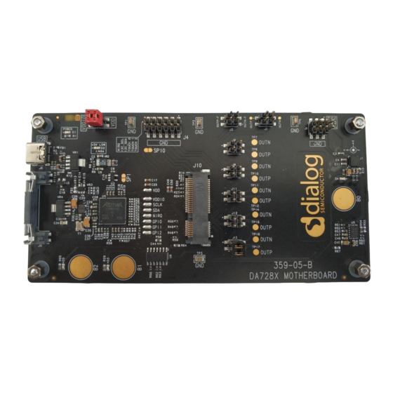
Table Figure 1: Bare 359-05-B motherboard DA728x Motherboard 359-05-B PCB Layout and Connections Figure 2: DA728x Motherboard 359-05-B PCB Layout User Manual Revision 1.1 - DRAFT 08-Jun-2022 6 of 59 © 2022 Renesas Electronics CFR0012... -
Page 7: Table 1: Jumper Connections And Descriptions
Mechanical lock for the Used to hold the daughterboard in place when fitted DA728x daughterboard Socket for the DA728x Electrical connections to/from the DA728x daughterboard daughterboard when fitted User Manual Revision 1.1 - DRAFT 08-Jun-2022 7 of 59 © 2022 Renesas Electronics CFR0012... -
Page 8: Hardware And Software Prerequisites
Quick Start Setup (Using DA7280 Daughterboard as an Example) Hardware Configuration To USB port Figure 3: DA728x Motherboard Operation with LRA Attached to DA7280 Daughterboard User Manual Revision 1.1 - DRAFT 08-Jun-2022 8 of 59 © 2022 Renesas Electronics CFR0012... -
Page 9: Configuration Steps
DA7280 daughterboard to work with the CapSense buttons (B0, B1, and B2) on the DA728x Motherboard. 8. Touching B0, B1, or B2 CapSense buttons on the DA728x Motherboard triggers the programmed haptic sequences. User Manual Revision 1.1 - DRAFT 08-Jun-2022 9 of 59 © 2022 Renesas Electronics CFR0012... -
Page 10: Smartcanvas Da728X Gui Setup
Follow the steps in the Setup Wizard to set up Dialog’s SmartCanvas DA728x GUI. 1. Click the “I accept the agreement” radio button and click “Next” (Figure Figure 6: License Agreement User Manual Revision 1.1 - DRAFT 08-Jun-2022 10 of 59 © 2022 Renesas Electronics CFR0012... -
Page 11: Figure 7: Select Installation Location
Figure 7: Select Installation Location 3. Create a shortcut for the SmartCanvas DA728x GUI in the Start Menu and click Next (Figure Figure 8: Select Start Menu Folder User Manual Revision 1.1 - DRAFT 08-Jun-2022 11 of 59 © 2022 Renesas Electronics CFR0012... -
Page 12: Figure 9: Create A Desktop Item
4. Create a desktop item for the SmartCanvas DA728x GUI and click Next (Figure Figure 9: Create a Desktop Item 5. Click Install. Figure 10: Install the SmartCanvas DA728x GUI User Manual Revision 1.1 - DRAFT 08-Jun-2022 12 of 59 © 2022 Renesas Electronics CFR0012... -
Page 13: Manual Driver Installation
If there are any issues with the USB-IO driver installation, such as a failed installation or the driver has been accidently removed or deleted, users can easily re-install the USB driver by navigating to User Manual Revision 1.1 - DRAFT 08-Jun-2022 13 of 59 © 2022 Renesas Electronics CFR0012... -
Page 14: Da728X Motherboard Hardware Overview
Analogue Accelerometer X/Y/Z outputs Analog accelerometer Solder bump Isolation points CapSense button GPI_0 GPI_2 GPI_1 Digital accelerometer OUTP/N select CapSense buttons Figure 15: DA728X Motherboard Functionality User Manual Revision 1.1 - DRAFT 08-Jun-2022 14 of 59 © 2022 Renesas Electronics CFR0012... -
Page 15: Power
To use external I2C communication, de-solder the SDA (Shorting point 5- Marked SP5) and SCL (Shorting point 4 - Marked SP4) solder bumps and connect the external I2C wires to J4, SCL (J4 pin User Manual Revision 1.1 - DRAFT 08-Jun-2022 15 of 59 © 2022 Renesas Electronics CFR0012... -
Page 16: Plug-In Daughterboards
The back end of the daughterboard should then be lowered to mate with J9 on the motherboard so that the back end of the daughterboard clips into the J9 connector as shown in Figure User Manual Revision 1.1 - DRAFT 08-Jun-2022 16 of 59 © 2022 Renesas Electronics CFR0012... -
Page 17: Da7280 Daughterboard
LRA should be placed on the motherboard for the true performance measurements of the acceleration. Please check the DA7280 daughterboard user manual for more information about the hardware and connections available on the board. User Manual Revision 1.1 - DRAFT 08-Jun-2022 17 of 59 © 2022 Renesas Electronics CFR0012... -
Page 18: Da7281 Daughterboard
LRA should be placed on the motherboard for the true performance measurements of the acceleration. Please check the DA7281 daughterboard user manual for more information about the hardware and connections available on the board. User Manual Revision 1.1 - DRAFT 08-Jun-2022 18 of 59 © 2022 Renesas Electronics CFR0012... -
Page 19: Da7282 Daughterboard
LRA should be placed on the motherboard for the true performance measurements of the acceleration. Please check the DA7282 daughterboard user manual for more information about the hardware and connections available on the board. User Manual Revision 1.1 - DRAFT 08-Jun-2022 19 of 59 © 2022 Renesas Electronics CFR0012... -
Page 20: Da7283 Daughterboard
Filtered OUT_P and OUT_N signals from DA7283 are available for debug and are accessed from the OUTP_F and OUTN_F pins (J2). Connect these signals from J2 to an oscilloscope for signal monitoring and tuning purposes (see section 10). User Manual Revision 1.1 - DRAFT 08-Jun-2022 20 of 59 © 2022 Renesas Electronics CFR0012... -
Page 21: Analog Accelerometer
Isolation points GPI_0 GPI_2 GPI_1 Digital accelerometer OUTP/N select CapSense buttons Figure 15). This is used to evaluate and tune the LRA's performance (see section 10). User Manual Revision 1.1 - DRAFT 08-Jun-2022 21 of 59 © 2022 Renesas Electronics CFR0012... -
Page 22: Digital Accelerometer
Please note that the copper sheet on the underside of the PCB must be left in place to shield the CapSense buttons from false triggering through detection of fields from the underside of the PCB. User Manual Revision 1.1 - DRAFT 08-Jun-2022 22 of 59 © 2022 Renesas Electronics CFR0012... -
Page 23: Additional Lra Connection
OUT P/N OUT_P/N Analogue Accelerometer connections X/Y/Z outputs Analog accelerometer Solder bump Isolation points GPI_0 GPI_2 GPI_1 Digital accelerometer OUTP/N select CapSense buttons Figure 15). User Manual Revision 1.1 - DRAFT 08-Jun-2022 23 of 59 © 2022 Renesas Electronics CFR0012... -
Page 24: Software Control
No diagram will be displayed for the DA7283 daughterboard (359-09), as it has no I2C access and is therefore not able to communicate with the SmartCanvas DA728x GUI. User Manual Revision 1.1 - DRAFT 08-Jun-2022 24 of 59 © 2022 Renesas Electronics CFR0012... -
Page 25: Figure 23: Da728X Motherboard Board Setup With Da7280 Daughterboard Connected
Bus and USB communication LEDs are green, confirming that the SmartCanvas DA728x GUI ● has established communications with the DA728x motherboard Enable/Disable Polling button is green and states Enabled ● Figure 24: Main SmartCanvas DA728x GUI Window User Manual Revision 1.1 - DRAFT 08-Jun-2022 25 of 59 © 2022 Renesas Electronics CFR0012... -
Page 26: Lra Configuration Scripts
9.1.1 Load LRA Configuration scripts 1. In the File I/O section 25), click the Load File button. (Figure Figure 25: File I/O User Manual Revision 1.1 - DRAFT 08-Jun-2022 26 of 59 © 2022 Renesas Electronics CFR0012... -
Page 27: Save All Registers
.txt is the default file type, however .csv format also saves the IRQ status registers. The .csv format can be useful for debugging purposes. User Manual Revision 1.1 - DRAFT 08-Jun-2022 27 of 59 © 2022 Renesas Electronics CFR0012... -
Page 28: Configuration Scripts For Supplied Lra
Rise time (50 %) = max 10 ms ● Fall time (50 %) = max 50 ms ● Measured impedance = 13 Ω ● Measured inductance = 353 µH User Manual Revision 1.1 - DRAFT 08-Jun-2022 28 of 59 © 2022 Renesas Electronics CFR0012... -
Page 29: Figure 28: Jahwa 1040 Lra Characteristics Graph
LRA is likely to be damaged due to the higher drive current used. 9.1.3.1 JAHWA_1040_FREQ_TRACK_ON The JAHWA_1040_FREQ_TRACK_ON.txt script sets up the DA728x to enable the features shown in Table User Manual Revision 1.1 - DRAFT 08-Jun-2022 29 of 59 © 2022 Renesas Electronics CFR0012... -
Page 30: Figure 29: Jahwa_1040_Freq_Track_On Parameters
After downloading the LRA configuration scripts, the impedance and inductance values are not updated, but the underlying registers in DA728x are set correctly for the LRA User Manual Revision 1.1 - DRAFT 08-Jun-2022 30 of 59 © 2022 Renesas Electronics CFR0012... -
Page 31: Figure 30: Jahwa_1040_Freq_Track_On Sequences
Frequency tracking Acceleration Rapid stop After the script is loaded, the SmartCanvas DA728x GUI shows the parameter settings applied by the configuration script (Figure 31). User Manual Revision 1.1 - DRAFT 08-Jun-2022 31 of 59 © 2022 Renesas Electronics CFR0012... -
Page 32: Figure 31: Jahwa_1040_Freq_Track_On_Rs_On Parameters
UM-HA-001 DA728x Motherboard 359-05-B Preliminary for Use with Evaluation Kit Figure 31: JAHWA_1040_FREQ_TRACK_ON_RS_ON Parameters User Manual Revision 1.1 - DRAFT 08-Jun-2022 32 of 59 © 2022 Renesas Electronics CFR0012... -
Page 33: Figure 32: Jahwa_1040_Freq_Track_On_Rs_On Sequences
Acceleration and Rapid Stop, Frequency Tracking is also off. Table 5: JAHWA_1040_FREQ_TRACK_OFF_SINE Script Features: Feature Status Frequency tracking Acceleration User Manual Revision 1.1 - DRAFT 08-Jun-2022 33 of 59 © 2022 Renesas Electronics CFR0012... -
Page 34: Figure 33: Jahwa_1040_Freq_Track_Off_Sine Parameters
Rapid stop After the script is loaded, the SmartCanvas DA728x GUI shows the parameter settings applied by the configuration script (Figure 33). Figure 33: JAHWA_1040_FREQ_TRACK_OFF_SINE Parameters User Manual Revision 1.1 - DRAFT 08-Jun-2022 34 of 59 © 2022 Renesas Electronics CFR0012... -
Page 35: Figure 34: Jahwa_1040_Freq_Track_Off_Sine Sequences
The JAHWA_1040_FREQ_TRACK_ON(2xLRA-IN-PARALLEL).txt script sets up the DA728x to enable the features shown in Table Table 6: JAHWA_1040_FREQ_TRACK_ON Script Features: Feature Status Frequency tracking Acceleration Rapid stop User Manual Revision 1.1 - DRAFT 08-Jun-2022 35 of 59 © 2022 Renesas Electronics CFR0012... -
Page 36: Figure 35: Jahwa_1040_Freq_Track_On(2Xlra-In-Parallel) Sequences
The haptic sequences loaded from the configuration scripts are displayed in the DA728x GUI (see Section 9.3). For the JAHWA_1040_FREQ_TRACK_ON2xLRA-IN-PARALLEL) script, the sequences are shown in Figure 30. User Manual Revision 1.1 - DRAFT 08-Jun-2022 36 of 59 © 2022 Renesas Electronics CFR0012... -
Page 37: Operation Modes
3. Use the drop-down menu in Operation Mode to select Direct register override. First setting the override value and then setting the operation mode to DRO ensures the optimal latency of the LRA. User Manual Revision 1.1 - DRAFT 08-Jun-2022 37 of 59 © 2022 Renesas Electronics CFR0012... -
Page 38: Register Triggered Waveform Memory (Rtwm)
5. Click the Sequence Start button to trigger the chosen sequence. The haptic sequences in the Waveform Memory can be edited, created, and triggered from the Waveform memory editor (see section 9.3). User Manual Revision 1.1 - DRAFT 08-Jun-2022 38 of 59 © 2022 Renesas Electronics CFR0012... -
Page 39: Playback From Pwm Data Source
PWM signal may be below the brake threshold value. ● Stopping the PWM input signal before exiting PWM mode will also result in an IRQ which must be cleared manually. User Manual Revision 1.1 - DRAFT 08-Jun-2022 39 of 59 © 2022 Renesas Electronics CFR0012... -
Page 40: Edge Triggered Waveform Memory (Etwm)
Sync > Read from Device in the Waveform Memory Editor (Figure 42) to read back the Waveform Memory from DA728x to ensure that the display is synchronized with the device memory. User Manual Revision 1.1 - DRAFT 08-Jun-2022 40 of 59 © 2022 Renesas Electronics CFR0012... -
Page 41: Snippets Tab
Drop Ramp or Step PWL points for right in here to create snippets Figure 43: Waveform Memory Editor Snippets Tab User Manual Revision 1.1 - DRAFT 08-Jun-2022 41 of 59 © 2022 Renesas Electronics CFR0012... -
Page 42: Sequences Tab
Note that if it is used for wideband patterns, frequency tracking should be switched off. NOTE The overall time of each sequence = Unit Time × Cycles × Timebase User Manual Revision 1.1 - DRAFT 08-Jun-2022 42 of 59 © 2022 Renesas Electronics CFR0012... -
Page 43: Wav To Haptics Converter
Select Wav to Haptics Converter from the Tools menu in the SmartCanvas DA728x GUI (Figure 47) and then press the Load File button in the plugin (Figure 48). Figure 47: Launching Wav to Haptics Converter User Manual Revision 1.1 - DRAFT 08-Jun-2022 43 of 59 © 2022 Renesas Electronics CFR0012... -
Page 44: Figure 48: Wav To Haptics Converter Plugin
GUI. A number .wav files of sound effects are included for demonstration purposes (Figure 49). Figure 49: Included Sound Effect Files User Manual Revision 1.1 - DRAFT 08-Jun-2022 44 of 59 © 2022 Renesas Electronics CFR0012... -
Page 45: Irq And Faults
To clear IRQ events, warnings and faults, click the buttons Clear Events and Clear Faults in the SmartCanvas DA728x GUI (see Figure 52). Any faults or warning are shown as a "High" in value for User Manual Revision 1.1 - DRAFT 08-Jun-2022 45 of 59 © 2022 Renesas Electronics CFR0012... -
Page 46: Capsense Setup
54). It is also possible to use the SmartCanvas DA728x GUI to set the state of the GPIs if edge triggering control is required from the SAM3U microcontroller. Figure 54: SAM3U Configuration User Manual Revision 1.1 - DRAFT 08-Jun-2022 46 of 59 © 2022 Renesas Electronics CFR0012... -
Page 47: Gpi Triggering From Gui
The GPIs can be controlled from the DA728x GUI's SAM3U Config tab, Each GPI can be changed by setting the IO Mode to Output: PushPull, then the IO state can be changed by pressing the IO State button (see Figure 57). User Manual Revision 1.1 - DRAFT 08-Jun-2022 47 of 59 © 2022 Renesas Electronics CFR0012... -
Page 48: Figure 57: Controlling Gpis From Gui
UM-HA-001 DA728x Motherboard 359-05-B Preliminary for Use with Evaluation Kit Figure 57: Controlling GPIs from GUI User Manual Revision 1.1 - DRAFT 08-Jun-2022 48 of 59 © 2022 Renesas Electronics CFR0012... -
Page 49: 10 Monitoring Drive Signals And Measuring Acceleration
3.6 V. Each of the outputs are low pass filtered to a bandwidth of 50 Hz. For more information on the accelerometer, please refer to https://www.analog.com/media/en/technical- documentation/data-sheets/ADXL335.pdf. Filtered Output Un-filtered Output Analogue accelerometer output Figure 58: Monitoring Signals User Manual Revision 1.1 - DRAFT 08-Jun-2022 49 of 59 © 2022 Renesas Electronics CFR0012... -
Page 50: 10.2 Digital Accelerometer
“Axis to sample” selection in the GUI. The data is then displayed in a graph which is useful for analyzing the output acceleration when an oscilloscope is not available. Figure 60: Digital Accelerometer User Manual Revision 1.1 - DRAFT 08-Jun-2022 50 of 59 © 2022 Renesas Electronics CFR0012... -
Page 51: Figure 61: Digital Accelerometer Gui
UM-HA-001 DA728x Motherboard 359-05-B Preliminary for Use with Evaluation Kit Figure 61: Digital Accelerometer GUI User Manual Revision 1.1 - DRAFT 08-Jun-2022 51 of 59 © 2022 Renesas Electronics CFR0012... -
Page 52: 11 Measuring Current On Vdd And Vddio
Alternatively, there is an option to set VDDIO to 3V3 by removing R13 and placing it on FB2 which is shown in Figure 62. Please see the motherboard schematic and layout User Manual Revision 1.1 - DRAFT 08-Jun-2022 52 of 59 © 2022 Renesas Electronics CFR0012... -
Page 53: 12 Measuring Current Going Through Lra
Figure 63 Figure Figure 63: Current measurement of drive current into LRA Figure 64: Green/Yellow Drive Signals (Sine Wave Mode), Magenta = Current Probe Output User Manual Revision 1.1 - DRAFT 08-Jun-2022 53 of 59 © 2022 Renesas Electronics CFR0012... -
Page 54: 13 Connecting Multiple Devices On The Same I2C Bus
To support multiple DA7281 devices, users can select which bus address is used by one device by selecting from the “Bus Interface” drop-down menu of the SmartCanvas DA728x GUI in the bottom right corner as shown in Figure User Manual Revision 1.1 - DRAFT 08-Jun-2022 54 of 59 © 2022 Renesas Electronics CFR0012... -
Page 55: Figure 66: Changing I2C Address Settings
DA7281 daughterboards to be enabled via a GPI to power the VDDIO supply so that four devices can be selected at a time for I2C communication. Please refer to the DA7281 datasheet further details. User Manual Revision 1.1 - DRAFT 08-Jun-2022 55 of 59 © 2022 Renesas Electronics CFR0012... -
Page 56: 13.1 I2C Scan Tool
Figure 68: I2C Scan Tool Pressing the “Scan” button interrogates the I2C bus and shows a list of data with the addresses of all devices found. User Manual Revision 1.1 - DRAFT 08-Jun-2022 56 of 59 © 2022 Renesas Electronics CFR0012... -
Page 57: Revision History
UM-HA-001 DA728x Motherboard 359-05-B Preliminary for Use with Evaluation Kit Revision History Revision Date Description Rebranded to Renesas. 08-Jun-2022 05-May-2020 Initial version. User Manual Revision 1.1 - DRAFT 08-Jun-2022 57 of 59 © 2022 Renesas Electronics CFR0012... - Page 58 The content of this document is under review and subject to formal approval, which may result in modifications or DRAFT additions. APPROVED The content of this document has been approved for publication. or unmarked User Manual Revision 1.1 - DRAFT 08-Jun-2022 58 of 59 © 2022 Renesas Electronics CFR0012...
- Page 59 Renesas disclaims responsibility for, and you will fully indemnify Renesas and its representatives against, any claims, damages, costs, losses, or liabilities arising out of your use of these resources. Renesas' products are provided only subject to Renesas' Terms and Conditions of Sale or other applicable terms agreed to in writing.
Need help?
Do you have a question about the DA728 Series and is the answer not in the manual?
Questions and answers