Sign In
Upload
Manuals
Brands
Renesas Manuals
Motherboard
DA728 Series
Renesas DA728 Series Haptic Driver Manuals
Manuals and User Guides for Renesas DA728 Series Haptic Driver. We have
2
Renesas DA728 Series Haptic Driver manuals available for free PDF download: User Manual
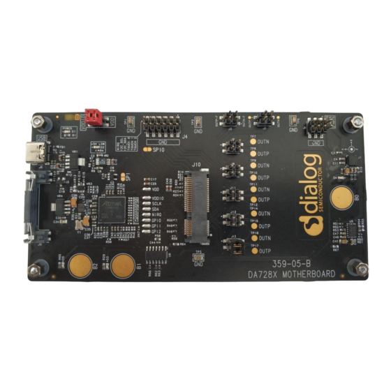
Renesas DA728 Series User Manual (61 pages)
Brand:
Renesas
| Category:
Motherboard
| Size: 4 MB
Table of Contents
Abstract
1
Table of Contents
2
Contents
2
Figures
3
Tables
4
Terms and Definitions
5
References
5
Introduction
6
Da728X Motherboard 359-05-B PCB Layout and Connections
6
Figure 1. Bare 359-05-B Motherboard
6
Figure 2. Da728X Motherboard 359-05-B PCB Layout
6
Table 1. Jumper Connections and Descriptions
7
Hardware and Software Prerequisites
9
Hardware Configuration
9
Figure 3. Da728X Motherboard Operation with LRA Attached to Da728X Motherboard
9
Da728X Motherboard Hardware Overview
10
Power
10
Figure 4. Da728X Motherboard Functionality
10
I 2 C Communications
11
Plug-In Daughterboards
11
Figure 5. Daughterboard Insertion
11
Figure 6. Daughterboard Fully Inserted with Release Tabs Shown
11
DA7280 Daughterboard
12
Figure 7. DA7280 Daughterboard
12
DA7281 Daughterboard
13
Figure 8. DA7281 Daughterboard
13
DA7282 Daughterboard
14
Figure 9. DA7282 Daughterboard
14
DA7283 Daughterboard
15
Figure 10. DA7283 Daughterboard
15
Analog Accelerometer
16
Digital Accelerometer
16
Plastic Mass Connection
16
Figure 11. Da728X Motherboard PCB Combined with Plastic Mass = 100 Grams
16
Additional LRA Connection
17
Configuration Steps
18
Figure 12. Placement of Da728X Motherboard for Optimal Haptic Feedback Measurements
18
Smartcanvas Da728X GUI Setup
19
Figure 13. License Agreement
19
Figure 14. Select Installation Location
19
Figure 15. Select Start Menu Folder
20
Figure 16. Create a Desktop Item
20
Figure 17. Install the Smartcanvas Da728X GUI
21
Figure 18. Finish Setup
21
Figure 19. Installing Driver Windows Notification
21
Manual Driver Installation
22
Figure 20. Installation Complete
22
Figure 21. Desktop Icon
22
Software Control
23
Figure 22. Da728X Motherboard Board Setup with DA7280 Daughterboard Connected
23
LRA Configuration Scripts
24
Load LRA Configuration Scripts
24
Figure 23. Main Smartcanvas Da728X GUI Window
24
Figure 24. File I/O
24
Save All Registers
25
Legacy Smartcanvas Da728X GUI Script Files
25
Configuration Scripts for Supplied LRA
25
Figure 25. Load File I/O Data
25
Figure 26. Old and New Format Script Files
25
Figure 27. JAHWA 1040 LRA Characteristics Graph
26
Table 2. JAHWA 1040 Configuration Script Details
26
Figure 28. JAHWA_1040_FREQ_TRACK_ON Parameters
27
Table 3. JAHWA_1040_FREQ_TRACK_ON Script Features
27
Figure 29. JAHWA_1040_FREQ_TRACK_ON Sequences
28
Table 4. JAHWA_1040_FREQ_TRACK_ON_RS_ON Script Features
28
Figure 30. JAHWA_1040_FREQ_TRACK_ON_RS_ON Parameters
29
Figure 31. JAHWA_1040_FREQ_TRACK_ON_RS_ON Sequences
29
Figure 32. JAHWA_1040_FREQ_TRACK_OFF_SINE Parameters
30
Table 5. JAHWA_1040_FREQ_TRACK_OFF_SINE Script Features
30
Figure 33. JAHWA_1040_FREQ_TRACK_OFF_SINE Sequences
31
Table 6. JAHWA_1040_FREQ_TRACK_ON Script Features
31
Figure 34. JAHWA_1040_FREQ_TRACK_ON(2Xlra-IN-PARALLEL) Sequences
32
TITAN Haptics Actuators
33
Figure 35. TITAN Haptics LF and HF Actuators
33
Figure 36. White Tape Shown on the Underside of HF and LF Actuators
33
Figure 37. Connection to Left Hand Pins of J11, Orientation Vibration for X-Axis (Arrow)
34
Operation Modes
35
Figure 38. TITAN DRAKE LF Example Waveforms
35
Figure 39. Operation Mode
35
Direct Register Override
36
Register Triggered Waveform Memory
36
Figure 40. Drive Type
36
Figure 41. Smartcanvas Da728X GUI in DRO Mode
36
Playback from PWM Data Source
37
Figure 42. Smartcanvas Da728X GUI in RTWM Mode
37
Edge Triggered Waveform Memory
38
Figure 43. GPI Registers
38
Waveform Memory Editor
39
Snippets and Sequences
39
Figure 44. Starting the Waveform Memory Editor in Da728X GUI
39
Figure 45. Register Syncing from Da728X Memory
39
Figure 46. Waveform Memory Editor Snippets Tab
40
Figure 47. Waveform Memory Editor Sequences Tab
40
Create Snippets
41
Figure 48. Snipper Creation
41
Figure 49. Second Snippet Waveform Addition
41
Create Sequences from Snippets
42
Figure 50. Complex Snippet Creation
42
Figure 51. Sequence Creation
42
Figure 52. Two Snippet Sequence Example
43
Figure 53. Snippets for Two-Snippet Sequence Example, 1 and 0
43
Edit Sequences
44
Detailed Information on Time-Base and Unit Time
44
Figure 54. Modifying Snippet Order in a Sequence
44
Real Playback Time V Approximate Playback Time
45
Wav to Haptics Converter
46
Figure 55. Launching Wav to Haptics Converter
46
Figure 56. Wav to Haptics Converter Tool
47
Figure 57. Included Sound Effect Files
47
IRQ and Faults
48
Figure 58. Detailed Descriptions of Controls
48
Figure 59. IRQ Tab
48
Capsense Setup
49
Figure 60. Clear IRQ Events and Faults
49
Figure 61. Embedded Mode
49
Figure 62. SAM3U Configuration
49
Figure 63. ETWM Mode
49
GPI Triggering from GUI
50
Figure 64. GPI_0_CTL Settings
50
Figure 65. Controlling Gpis from GUI
50
10 Monitor Drive Signals and Measuring Acceleration
51
10.1 Analogue Accelerometer
51
Figure 66. Monitoring Signals
51
10.2 Digital Accelerometer
52
Figure 67. Measured Output Signals and Acceleration Profile
52
Figure 68. Digital Accelerometer
52
Figure 69. Digital Accelerometer GUI
53
11 Measure Current on VDD and VDDIO
54
Figure 70. Current Measurement and External Supply Connections
54
12 Measure Current Going through LRA
55
Figure 71. Current Measurement of Drive Current into LRA
55
Figure 72. Green/Yellow Drive Signals (Sine Wave Mode), Magenta = Current Probe Output
55
13 Connect Multiple Devices on the same I2C Bus
56
Figure 73. Da728X Motherboard Configuration for Multiple DA7281 Daughterboards
56
Figure 74. Changing I2C Address Settings
56
Table 7. I2C Hex/Binary Settings for DA7281
57
13.1 I2C Scan Tool
58
Figure 75. Da728X Motherboard with Four DA7281 Daughterboards Stacked
58
Figure 76. I2C Scan Tool
58
Revision History
59
Advertisement
Renesas DA728 Series User Manual (59 pages)
Brand:
Renesas
| Category:
Motherboard
| Size: 6 MB
Table of Contents
Abstract
1
Table of Contents
2
Terms and Definitions
5
References
5
Introduction
6
Da728X Motherboard 359-05-B PCB Layout and Connections
6
Figure 1: Bare 359-05-B Motherboard
6
Figure 2: Da728X Motherboard 359-05-B PCB Layout
6
Table 1: Jumper Connections and Descriptions
7
Hardware and Software Prerequisites
8
Quick Start Setup (Using DA7280 Daughterboard as an Example)
8
Hardware Configuration
8
Figure 3: Da728X Motherboard Operation with LRA Attached to DA7280 Daughterboard
8
Configuration Steps
9
Figure 4: Da728X Motherboard Operation with LRA Attached to Da728X Motherboard
9
Smartcanvas Da728X GUI Setup
10
Figure 5: Placement of Da728X Motherboard for Optimal Haptic Feedback Measurements
10
Figure 6: License Agreement
10
Figure 7: Select Installation Location
11
Figure 8: Select Start Menu Folder
11
Figure 9: Create a Desktop Item
12
Figure 10: Install the Smartcanvas Da728X GUI
12
Manual Driver Installation
13
Figure 11: Finish Setup
13
Figure 12: Installing Driver Windows Notification
13
Figure 13: Installation Complete
13
Figure 14: Desktop Icon
13
Da728X Motherboard Hardware Overview
14
Figure 15: DA728X Motherboard Functionality
14
Power
15
I 2 C Communications
15
Plug-In Daughterboards
16
Figure 16: Daughterboard Insertion
16
DA7280 Daughterboard
17
Figure 17: Daughterboard Fully Inserted with Release Tabs Shown
17
Figure 18: DA7280 Daughterboard
17
DA7281 Daughterboard
18
Figure 19: DA7281 Daughterboard
18
DA7282 Daughterboard
19
Figure 20: DA7282 Daughterboard
19
DA7283 Daughterboard
20
Figure 21: DA7283 Daughterboard
20
Analog Accelerometer
21
Digital Accelerometer
22
Plastic Mass Connection
22
Additional LRA Connection
23
Figure 22: Da728X Motherboard PCB Combined with Plastic Mass as 100 G
23
Software Control
24
Figure 23: Da728X Motherboard Board Setup with DA7280 Daughterboard Connected
25
Figure 24: Main Smartcanvas Da728X GUI Window
25
LRA Configuration Scripts
26
Load LRA Configuration Scripts
26
Figure 25: File I/O
26
Save All Registers
27
Figure 26: Load Register Dump
27
Configuration Scripts for Supplied LRA
28
Figure 27: Old and New Format Script Files
28
Figure 28: JAHWA 1040 LRA Characteristics Graph
29
Table 2: JAHWA 1040 Configuration Script Details
29
Figure 29: JAHWA_1040_FREQ_TRACK_ON Parameters
30
Table 3: JAHWA_1040_FREQ_TRACK_ON Script Features
30
Figure 30: JAHWA_1040_FREQ_TRACK_ON Sequences
31
Table 4: JAHWA_1040_FREQ_TRACK_ON_RS_ON Script Features
31
Figure 31: JAHWA_1040_FREQ_TRACK_ON_RS_ON Parameters
32
Figure 32: JAHWA_1040_FREQ_TRACK_ON_RS_ON Sequences
33
Table 5: JAHWA_1040_FREQ_TRACK_OFF_SINE Script Features
33
Figure 33: JAHWA_1040_FREQ_TRACK_OFF_SINE Parameters
34
Figure 34: JAHWA_1040_FREQ_TRACK_OFF_SINE Sequences
35
Table 6: JAHWA_1040_FREQ_TRACK_ON Script Features
35
Figure 35: JAHWA_1040_FREQ_TRACK_ON(2Xlra-IN-PARALLEL) Sequences
36
Operation Modes
37
Direct Register Override (DRO)
37
Figure 36: Drive Type
37
Figure 37: Operation Mode
37
Register Triggered Waveform Memory (RTWM)
38
Figure 38: Smartcanvas Da728X GUI in DRO Mode
38
Playback from PWM Data Source
39
Figure 39: Smartcanvas Da728X GUI in RTWM Mode
39
Edge Triggered Waveform Memory (ETWM)
40
Waveform Memory Editor
40
Figure 40: GPI Registers
40
Figure 41: Enabling the Waveform Memory Editor in Da728X GUI
40
Snippets Tab
41
Figure 42: Register Syncing from Da728X Memory
41
Figure 43: Waveform Memory Editor Snippets Tab
41
Sequences Tab
42
Figure 44: Waveform Memory Editor Sequences Tab
42
Wav to Haptics Converter
43
Figure 45: Two Snippet Sequence Example
43
Figure 46: Snippets for the Two Snippet Sequence Example
43
Figure 47: Launching Wav to Haptics Converter
43
Figure 48: Wav to Haptics Converter Plugin
44
Figure 49: Included Sound Effect Files
44
IRQ and Faults
45
Figure 50: Detailed Descriptions of Controls
45
Figure 51: IRQ Tab
45
Capsense Setup
46
Figure 52: Clear IRQ Events and Faults
46
Figure 53: Embedded Mode
46
Figure 54: SAM3U Configuration
46
GPI Triggering from GUI
47
Figure 55: ETWM Mode
47
Figure 56: GPI_0_CTL Settings
47
Figure 57: Controlling Gpis from GUI
48
10 Monitoring Drive Signals and Measuring Acceleration
49
10.1 Analogue Accelerometer
49
Figure 58: Monitoring Signals
49
10.2 Digital Accelerometer
50
Figure 59: Measured Output Signals and Acceleration Profile
50
Figure 60: Digital Accelerometer
50
Figure 61: Digital Accelerometer GUI
51
11 Measuring Current on VDD and VDDIO
52
Figure 62: Current Measurement and External Supply Connections
52
12 Measuring Current Going through LRA
53
Figure 63: Current Measurement of Drive Current into LRA
53
Figure 64: Green/Yellow Drive Signals (Sine Wave Mode), Magenta = Current Probe Output
53
13 Connecting Multiple Devices on the same I2C Bus
54
Figure 65: Da728X Motherboard Configuration for Multiple DA7281 Daughterboards
54
Figure 66: Changing I2C Address Settings
55
Table 7: I2C Hex/Binary Settings for DA7281
55
13.1 I2C Scan Tool
56
Figure 67: Da728X Motherboard with Four DA7281 Daughterboards Stacked
56
Figure 68: I2C Scan Tool
56
Revision History
57
Advertisement
Related Products
Renesas DA7210
Renesas DA7211
Renesas DA7280
Renesas DA7281
Renesas DA7282
Renesas DA7283
Renesas DA9061-63
Renesas DA9061
Renesas DA9062
Renesas DA9066
Renesas Categories
Computer Hardware
Motherboard
Microcontrollers
Adapter
Switch
More Renesas Manuals
Login
Sign In
OR
Sign in with Facebook
Sign in with Google
Upload manual
Upload from disk
Upload from URL