Table of Contents
Advertisement
Quick Links
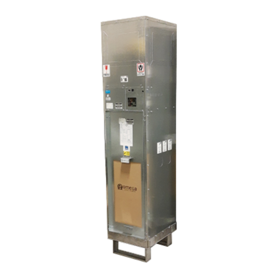
OMEGA VSHYe SERIES
Installation and Operation Manual (IOM)
VERTICAL STACKED
HYBRID HEATING & COOLING
W/ INTEGRATED ERV
HIGH EFFICIENCY (HE)
MODEL: VSHYe
DEV. F
DOCUMENT RELEASE: OMEGA-VSHYe.F-IOM-2108
Initial Release
3325A Orlando Dr.
Mississauga, ON, L4V 1C5
T. 905.670.2269
omega-heatpump.com
omega@omega-heatpump.com
Advertisement
Table of Contents

Related Manuals for Omega VSHYe Series


Summary of Contents for Omega VSHYe Series
- Page 1 OMEGA VSHYe SERIES Installation and Operation Manual (IOM) VERTICAL STACKED HYBRID HEATING & COOLING W/ INTEGRATED ERV HIGH EFFICIENCY (HE) MODEL: VSHYe DEV. F DOCUMENT RELEASE: OMEGA-VSHYe.F-IOM-2108 Initial Release 3325A Orlando Dr. Mississauga, ON, L4V 1C5 T. 905.670.2269 omega-heatpump.com omega@omega-heatpump.com...
-
Page 2: Table Of Contents
OMEGA-VSHYe.F-IOM-2108 TABLE OF CONTENTS 1. General Information, Warnings and Disclaimer ..............1 2. Cabinet Dimensions ....................... 2 3. General Unit Information ......................5 4. Inspection & Storage ......................5 Inspection of Unit ......................5 Storage ......................... 6 5. Cabinet & Riser Installation ....................6 For Shipped Loose Riser Shut-Off Valves .............. -
Page 3: General Information, Warnings And Disclaimer
OMEGA-VSHYe.F-IOM-2108 IMPORTANT READ THE FOLLOWING MANUAL PRIOR TO INSTALLATION, OPERATION and SER- VICING THIS UNIT. 1. GENERAL INFORMATION & WARNINGS SAFETY SYMBOLS – Warnings, Cautions & Notices There are three advisory symbols used in this document to alert the reader: Warning: Indicates a potentially dangerous situation which could result in death or serious injury. -
Page 4: Cabinet Dimensions
OMEGA-VSHYe.F-IOM-2108 2. CABINET DIMENSIONS VSHYe Cabinet Dimensions Dimensions (in) VSHPe Supply Discharge Opening ("W" X "H") inches Capacity Cabinet Model (Tons) Size Front Back Right/Left 14 x 8 8 x 14 10 x 12 12 x 12 VSHYe 030 VSHYe 040... - Page 5 OMEGA-VSHYe.F-IOM-2108 Notes: Temporary riser supports provided (Contractor to remove and install permanent riser clamps fastening risers to the building structure). Return air opening is on the front of the unit. Unit includes hose kits and manual shut off valves.
- Page 6 OMEGA-VSHYe.F-IOM-2108 1. Supply, return and condensate riser field “knockouts”. 2. Field “knockout” supply air openings (Front/Back/Side/Top) with 1-1/2” duct flange. 3. ERV Ports—Bathroom Exhaust, Exhaust Air, Outside Air. 4. Removable ERV core. 5. Chassis (HP shown) 6. Chassis service cover panel.
-
Page 7: General Unit Information
OMEGA-VSHYe.F-IOM-2108 3. GENERAL UNIT INFORMATION cessing and servicing the ERV core, sensors and fans. The upper panel comes as either a blank panel or with a BLOWER & MOTOR supply grille. Removal of this panel allows access to The unit comes with a blower and motor assembly that outdoor air (OA) actuator. -
Page 8: Cabinet & Riser Installation
OMEGA-VSHYe.F-IOM-2108 rior insulation becoming wet and cause the growth FOR SHIPPED LOOSE RISER SHUT-OFF VALVES of mold which is known to cause odors and serious Visually inspect riser stub-outs and shut-off indoor air quality problems and health issues. valves for debris or damage. -
Page 9: Riser Loop
OMEGA-VSHYe.F-IOM-2108 8. Secure risers to building structure as per engineer- Chassis installation is permitted once the riser system is ing design specifications. Do not allow the risers to be thoroughly flushed, cleaned, and water loop is chemical- supported by the cabinets. Field supplied riser compen-... -
Page 10: Chassis Installation
OMEGA-VSHYe.F-IOM-2108 6. CHASSIS INSTALLATION return connections. Hand tighten, then using a back-up wrench tighten fittings as necessary. Ensure that the Do not apply plumbers putty, pipe dope or hose supply and return connections are not reversed sealing tape to NPSM fittings. -
Page 11: Unit Start-Up
OMEGA-VSHYe.F-IOM-2108 7. UNIT START-UP INITIAL QUICK UNIT START-UP GUIDE If not familiar with equipment operation see sections that Ensure the building fluid loop system has been cleaned, follow on microprocessor controller settings, sequence flushed, re-filled, chemically treated and commissioned of operation, and ERV fan balancing before proceeding by the water treatment company. -
Page 12: Controls
OMEGA-VSHYe.F-IOM-2108 8. CONTROLS ‘G1’ terminals on TB1 of control board to enable Whis- per mode. With Whisper Mode DIP Switch #6 is set to 8.1 MICROPROCESSOR CONTROLLER (ON) Auto. The manual fan speed switch is not used. DIP Switch Settings... -
Page 13: Fan Control With Ecm
OMEGA-VSHYe.F-IOM-2108 When call for cooling request is terminated, the auto state, do not disconnect power to unit in an attempt shut-off control valve (COAX Flow Valve) and the blower to restart to unit. The unit will allow 3 faults before it fan will remain open for an additional 3 minutes. -
Page 14: Erv Controls & Operation
OMEGA-VSHYe.F-IOM-2108 8.4 ERV CONTROLS & OPERATION When the timer switch puts the unit on high speed mode for the set time and the high speed LED (LD2) lights up. ERV Control Board After the timer cycle is expired the unit ERV fans return... -
Page 15: Erv Fan Settings
OMEGA-VSHYe.F-IOM-2108 ERV controller will modulate the OA damper to maintain SA temperatures above this threshold. The modulating damper provides maximum fresh air and avoids the dumping of cold air. This mode is disabled during the recycled air defrost mode. ERV FAN SETTINGS ERV Fan Setting The ERV fans are factory set to default position. -
Page 16: Web Browser Access
OMEGA-VSHYe.F-IOM-2108 9. WEB BROWSER ACCESS 3. On laptop access “Network and Sharing Center“ The Omega controller hosts a webpage configuration though the “Network & Internet Settings” icon located in and troubleshooting aid. There are two ways to connect: the bottom right taskbar. - Page 17 OMEGA-VSHYe.F-IOM-2108 9. An event log feature called Log Dump allows for re- cording unit operation information during faults or at start -up as a troubleshooting aid. For example in the figure below the first line item indicates “Y” terminal was ener- gized (Y=1) when the Cooling (CLG=1) and tripped on Low Pressure fault (LP=0).
-
Page 18: Maintenance Guide
OMEGA-VSHYe.F-IOM-2108 10. MAINTENANCE GUIDE air coil may occur resulting in possible refrigerant leaks. Proper unit maintenance will result in optimal unit perfor- ANNUAL MAINTENANCE mance and prevent potentially costly repairs or property damage. Turn unit disconnect switch to off and turn unit... - Page 19 OMEGA-VSHYe.F-IOM-2108 Table 8: Troubleshooting Guide Problem Mode Possible Cause(s) Correction Method Check unit disconnect switch/ circuit breaker/ fuses Heating/Cooling Main power off Heating/Cooling Defective control transformer Confirm thermostat is wired correctly before replacing No response to any thermostat Check thermostat wiring. Isolate thermostat. Check for for loose thermostat connections.
- Page 20 OMEGA-VSHYe.F-IOM-2108 Table 9: Microprocessor LED Code Guide Description LED Code Alarm Description Red = Solid High pressure alarm. Hard Lock-Out. 3 Trips High Pressure Red = Blinking High pressure alarm. Soft Lock-Out Red = Solid Low pressure alarm. Hard Lock-Out. 3 Trips...
- Page 21 OMEGA-VSHYe.F-IOM-2108 2" 2" 8" 8" (Typ.) (Typ.) 6" Chassis Chassis Chassis 12" 2" (Typ.) 2" FRONT Return Air FRONT Return Air FRONT Return Air Left Hand Riser (LH-SR) Back Riser (BK-SR) Right Hand Riser (RH-SR) Chassis Chassis Chassis FRONT Return Air...
- Page 22 Offset indicates where the top of riser will be located relative to top of cabinet. A Base Datum indicates where bottom of riser will be located relative to base of cabinet. Upon request Omega will provide 3 inch deep swage on risers of same pipe size (optional for all risers) for connection to units on the floor below. ...
- Page 23 OMEGA-VSHYe.F-IOM-2108 Acoustic ERV RA Panel Dimensional Drawing Acoustic ERV RA Panel Sizes Acoustic RA Panel Dimensions Cabinet (inches) Model Size VSHYe 030 VSHYe 040 19 5/8 VSHYe 050 VSHYe 060 VSHYe 080 23 5/8 VSHYe 100 VSHYe 120 NOTES: ...
- Page 24 OMEGA-VSHYe.F-IOM-2108 Acoustic Return Air Panel Baseboard Cabinet Base 1.25" Flooring Concrete Slab Acoustic Panel Cabinet Base Height Calculation Acoustic ERV Panel Cabinet Base Height Calculation: Example: Baseboard - Base Height = Baseboard Height + Finish Floor Height* Baseboard Height* Cabinet Base Height = Gap (recommend min 0.5”) between baseboard and...
- Page 25 OMEGA-VSHYe.F-IOM-2108 PLAN VIEW VSHP CABINET & ACOUSTIC RETURN AIR PANEL Unit Cabinet to Back Wall: No Risers = Min. 1/2" W/ Risers = Min. 8" Typ. VSHPe/VSHYe CABINET Unit Cabinet to Left/Right Wall: W/ Nom. 2"x2" Studs = Min. 1-1/2"...
- Page 26 OMEGA-VSHYe.F-IOM-2108 Acoustic RA Panel Furring Sizes Cabinet Rough-In (in) Cabinet Dimensions (in) Model Size "X" "Y" VSHYe 030 VSHYe 040 21 1/2 20 1/8 78 1/2 VSHYe 050 VSHYe 060 Field Gasket Supply Grille VSHYe 080 Throat 25 1/2 24 1/8...
- Page 27 OMEGA-VSHYe.F-IOM-2108 VHSYe Electrical Schematic—ECM Fan...
- Page 28 OMEGA-VSHYe.F-IOM-2108 Power Cable Entrance Low Voltage Notch For Control Wire Optional Front Entrance Low Voltage Control Wire Entrance Factory supplied 6- wire thermostat cable shown. Whisper Mode standard on G1 G2 Y O/B C VSHYe units. Jumper between R and G1...
- Page 29 OMEGA-VSHYe.F-IOM-2108 ECM Fan Data External Static Pressure (in w.g.) Unit EC Motor Minimum Rated 0.05 0.15 0.25 0.35 0.45 0.55 Size Speed SCFM SCFM SCFM SCFM SCFM SCFM SCFM SCFM SCFM SCFM SCFM SCFM SCFM SCFM SCFM WHISPER* MODE HIGH...
- Page 30 Fan Speed Used: High Fan Amp: ________ Compressor Amp: ________ Run Time For Test: ________ Fan Amp: ________ Run Time For Test: ________ Omega has a policy of continuous product improvement and reserves the right to change design and specifications without notice.
- Page 31 ERV Air Balance Check: ____ Yes/No ERV Bathroom Timer On: ERV Bathroom Timer Wired: ____Yes/No ERV Fan Speed Ramps to High: ___ Yes/No Omega has a policy of continuous product improvement and reserves the right to change design and specifications without notice.
Need help?
Do you have a question about the VSHYe Series and is the answer not in the manual?
Questions and answers