
Subscribe to Our Youtube Channel
Related Manuals for Omega OM-USB-TEMP-AI


Summary of Contents for Omega OM-USB-TEMP-AI
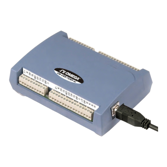
- Page 1 User’ s Guide Extended Warranty Program Shop online at omega.com e-mail: info@omega.com For latest product manuals: omegamanual.info OM-USB-TEMP-AI 8 Channel Temperature/Voltage Measurement USB Data Acquisition Module...
- Page 2 Approach Directives. OMEGA will add the CE mark to every appropriate device upon certification. The information contained in this document is believed to be correct, but OMEGA accepts no liability for any errors it contains, and reserves the right to alter specifications without notice.
-
Page 3: Table Of Contents
Introducing the OM-USB-TEMP-AI ......................6 Overview: OM-USB-TEMP-AI features........................6 OM-USB-TEMP-AI block diagram ......................... 7 Software features ............................... 7 Connecting a OM-USB-TEMP-AI to your computer is easy.................. 8 Chapter 2 Installing the OM-USB-TEMP-AI ....................... 9 What comes with your OM-USB-TEMP-AI shipment?..................9 Hardware .....................................9... - Page 4 OM-USB-TEMP-AI User's Guide Open-thermocouple detection (OTD) ............................19 RTD and thermistor measurements ........................19 Data linearization..................................20 USB connector................................. 20 LED..................................20 Power ..................................20 Chapter 5 Specifications............................21 Analog input ................................21 Channel configurations ............................23 Compatible sensors: T0x-T3x ..............................24 Accuracy .................................. 24 Thermocouple measurement accuracy: T0x-T3x........................24...
-
Page 5: Preface
About this User’s Guide What you will learn from this user’s guide This user’s guide explains how to install, configure, and use the OM-USB-TEMP-AI so that you get the most out of its USB-based temperature and voltage measurement features. This user’s guide also refers you to related documents available on our web site, and to technical support resources. -
Page 6: Introducing The Om-Usb-Temp-Ai
Introducing the OM-USB-TEMP-AI Overview: OM-USB-TEMP-AI features This user's guide contains all of the information you need to connect the OM-USB-TEMP-AI to your computer and to the signals you want to measure. The OM-USB-TEMP-AI is a USB 2.0 full-speed, temperature measurement module that is supported under ®... -
Page 7: Om-Usb-Temp-Ai Block Diagram
OM-USB-TEMP-AI User's Guide Introducing the OM-USB-TEMP-AI OM-USB-TEMP-AI block diagram OM-USB-TEMP-AI functions are illustrated in the block diagram shown here. Figure 1. OM-USB-TEMP-AI functional block diagram Software features For information on the features of InstaCal and the other software included with your OM-USB-TC, refer to the OMB-DAQ-2416 Series and OM-USB Series Data Acquisition Software User’s Guide that shipped with your... -
Page 8: Connecting A Om-Usb-Temp-Ai To Your Computer Is Easy
Microsoft HID because it is a standard, and its performance delivers full control and maximizes data transfer rates for your OM-USB-TEMP-AI. No third-party device driver is required. The OM-USB-TEMP-AI is plug-and-play. There are no jumpers to position, DIP switches to set, or interrupts to configure. -
Page 9: Installing The Om-Usb-Temp-Ai
As with any electronic device, you should take care while handling to avoid damage from static electricity. Before removing the OM-USB-TEMP-AI from its packaging, ground yourself using a wrist strap or by simply touching the computer chassis or other grounded object to eliminate any stored static charge. -
Page 10: Installing The Software
Installing the OM-USB-TEMP-AI To connect the OM-USB-TEMP-AI to your system, turn your computer on, and connect the USB cable to a USB port on your computer or to an external USB hub that is connected to your computer. The USB cable provides power and communication to the OM-USB-TEMP-AI. -
Page 11: Signal I/O Connections
Screw terminal pin out The OM-USB-TEMP-AI has four rows of screw terminals — two rows on the top edge of the housing, and two rows on the bottom edge. Each row has 26 connections. Between screw terminals 10 and 11 is the integrated CJC sensor used for thermocouple measurements. -
Page 12: Voltage Input Terminals (±V0H/V0L To ±V3H/V3L)
GND. A value of approximately 100 k_ can be used for most applications. Caution! All ground pins on the OM-USB-TEMP-AI (pins 9, 19, 22, 27, 30, 33, 36, 39, 49) are common and are isolated from earth ground. If a connection is made to earth ground when using digital I/O and conductive thermocouples, the thermocouples are no longer isolated. -
Page 13: Current Excitation Output Terminals (±I1 And ±I2)
TTL level transitions from low to high. The counter can count events at frequencies of up to 1 MHz. Caution! All ground pins on the OM-USB-TEMP-AI (pins 9, 19, 22, 27, 30, 33, 36, 39, 49) are common and are isolated from earth ground. If a connection is made to earth ground when using digital I/O and conductive thermocouples, the thermocouples are no longer isolated. -
Page 14: Power Terminal (+5V)
Use InstaCal to select the thermocouple type (J, K, R, S, T, N, E, and B) on one or more sensor input channels to connect the thermocouple. Wiring configuration Connect the thermocouple to the OM-USB-TEMP-AI using a differential configuration, as shown in Figure 3. Figure 3. Typical thermocouple connection The OM-USB-TEMP-AI pins are isolated from earth ground. -
Page 15: Two-Wire Configuration
RTD maximum resistance Resistance values greater than 660 _ cannot be measured by the OM-USB-TEMP-AI in the RTD mode. The 660 _ resistance limit includes the total resistance across the current excitation (±Ix) pins, which is the sum of the RTD resistance and the lead resistances. -
Page 16: Three-Wire Configuration
Connect your sensor with a four-wire configuration when your application requires very high accuracy measurements. Examples of a four-wire single-sensor measurement configuration are shown in Figure 7 and Figure 8. You can configure the OM-USB-TEMP-AI with either a single sensor per channel or two sensors per channel pair. Four-wire, single-sensor... -
Page 17: Semiconductor Sensor Measurements
RTDs. However, semiconductor sensors can be accurate, inexpensive and easy to interface with other electronics for display and control. The OM-USB-TEMP-AI makes high-resolution measurements of semiconductor sensors, such as the LM36 or equivalent, and returns a 32-bit floating point value in either a voltage or temperature format. -
Page 18: Wiring Configuration
Figure 11. Schematic showing switch detection by digital channel DIO0 Caution! All ground pins on the OM-USB-TEMP-AI (pins 9, 19, 22, 27, 30, 33, 36, 39, 49) are common and are isolated from earth ground. If a connection is made to earth ground when using digital I/O and conductive thermocouples, the thermocouples are no longer isolated. -
Page 19: Chapter 4 Functional Details
+2.5 V to the thermocouple’s low side at the C#L input. Always connect thermocouple sensors to the OM-USB-TEMP-AI in a floating fashion. Do not attempt to connect the thermocouple low side C#L to GND or to a ground referencing resistor. -
Page 20: Data Linearization
The USB connector provides +5V power and communication. No external power supply is required. The LED indicates the communication status of the OM-USB-TEMP-AI. It uses up to 5 mA of current. The table below defines the function of the OM-USB-TEMP-AI LED. -
Page 21: Specifications
Chapter 5 Specifications All specifications are subject to change without notice. Typical for 25 °C unless otherwise specified. All specifications apply to all temperature and voltage input channels unless otherwise specified. Specifications in italic text are guaranteed by design. Analog input Table 1. - Page 22 OM-USB-TEMP-AI User's Guide Specifications Parameter Conditions Specification V0x-V3x 10 Gigohm (power on) 2.49 kohm (power off) Input leakage current T0x-T3x, with open thermocouple 30 nA maximum detect disabled. T0x-T3x, with open thermocouple 105 nA maximum detect enabled. V0x-V3x ±1.5 nA typical., ±25 nA maximum...
-
Page 23: Channel Configurations
V0x-V3x Single-ended 4 single-ended channels Internally, the OM-USB-TEMP-AI has four, dual-channel, fully differential A/Ds providing a Note 1: total of eight input channels. The temperature input channels are configured as two channel pairs with T0x/T1x and T2x/T3x accepting temperature sensor type inputs. This "channel-pairing"... -
Page 24: Compatible Sensors: T0X-T3X
OM-USB-TEMP-AI User's Guide Specifications Compatible sensors: T0x-T3x Table 3. Compatible sensor type specifications Parameter Conditions Thermocouple J: -210 °C to 1200 °C K: -270 °C to 1372 °C R: -50 °C to 1768 °C S: -50 °C to 1768 °C T: -270 °C to 400 °C... -
Page 25: Semiconductor Sensor Measurement Accuracy: T0X-T3X
Thermocouples must be connected to the OM-USB-TEMP-AI such that they are floating with Note 6: respect to GND (pins 9, 19, 22, 27, 30, 33, 36, 39, 49). The OM-USB-TEMP-AI GND pins are isolated from earth ground. You can connect thermocouple sensors to voltages referenced to earth ground as long as the isolation between the GND pins and earth ground is maintained. -
Page 26: Thermistor Measurement Accuracy: T0X-T3X
Callendar-Van Dusen linearization algorithm. These specifications are for one year while operation of the OM-USB-TEMP-AI unit is between 15 °C and 35 °C. The specification does not include lead resistance errors for 2-wire thermistor connections. Contact your sensor supplier for details on the actual sensor error limitations. -
Page 27: Absolute Accuracy: V0X-V3X
GND. A value of approximately 1 Meg ohm can be used for most applications. All ground pins on the OM-USB-TEMP-AI (pins 9, 19, 22, 27, 30, 33, 36, 39, 49) are common Note 16: and are isolated from earth ground. If a connection is made to earth ground when using both voltage inputs and conductive thermocouples, the thermocouples are no longer isolated. -
Page 28: Settling Time: V0X-V3X
OM-USB-TEMP-AI User's Guide Specifications Settling time: V0x-V3x Table 12. Settling time specifications Range Accuracy ±0.0004% (seconds) ±10 V 15.0 ±5 V 0.40 ±2.5 V 0.40 ±1.25 V 0.40 Settling time is defined as the time required for a channel to settle within a specified accuracy in response to a full-scale (FS) step input. -
Page 29: Digital Input/Output
3.8 V minimum (IOH = -2.5 mA max.) All ground pins on the OM-USB-TEMP-AI (pins 9, 19, 22, 27, 30, 33, 36, 39, 49) are common Note 19: and are isolated from earth ground. If a connection is made to earth ground when using both digital I/O and conductive thermocouples, the thermocouples are no longer isolated. -
Page 30: Memory
5 mA maximum (terminal block pin 21) Isolation Measurement system to PC 500 VDC minimum This is the total current requirement for the OM-USB-TEMP-AI which includes up to 10 mA for Note 21: the status LED. USB specifications Table 21. USB specifications USB device type USB 2.0 (full-speed) -
Page 31: Current Excitation Outputs (±Ix, T0X-T3X)
(relative to GND pins 9, 19, 22, -0.03 V minimum 27, 30, 33, 36, 39) The OM-USB-TEMP-AI has two current excitation outputs, with ±I1 dedicated to the T0x/T1x Note 22: analog inputs, and ±I2 dedicated to T2x/T3x. The excitation output currents should always be used in this dedicated configuration. -
Page 32: Screw Terminal Connector Type And Pin Out
OM-USB-TEMP-AI User's Guide Specifications Screw terminal connector type and pin out Table 25. Screw terminal connector specifications Connector type Screw terminal Wire gauge range 16 AWG to 30 AWG Screw terminal pin out Table 26. Screw terminal pin out Signal Name... - Page 33 Department will issue an Authorized Return (AR) number immediately upon phone or written request. Upon examination by OMEGA, if the unit is found to be defective, it will be repaired or replaced at no charge. OMEGA’s WARRANTY does not apply to defects resulting from any action of the purchaser, including but not limited to mishandling, improper interfacing, operation outside of design limits, improper repair, or unauthorized modification.
- Page 34 Where Do I Find Everything I Need for Process Measurement and Control? OMEGA…Of Course! Shop online at omega.com TEMPERATURE Thermocouple, RTD & Thermistor Probes, Connectors, Panels & Assemblies Wire: Thermocouple, RTD & Thermistor Calibrators & Ice Point References Recorders, Controllers & Process Monitors...
Need help?
Do you have a question about the OM-USB-TEMP-AI and is the answer not in the manual?
Questions and answers