
Subscribe to Our Youtube Channel
Related Manuals for Omega CN1001-TC


Summary of Contents for Omega CN1001-TC
- Page 1 RoHS 2 Compliant User’ s Guide Shop on line at omega.com e-mail: info@omega.com For latest product manuals omegamanual.info CN1001-TC Programmable Digital Thermocouple/Temperature Meter with Time Proportional Control...
- Page 2 It is the policy of OMEGA to comply with all worldwide safety and EMC/EMI regulations that apply. OMEGA is constantly pursuing certification of its products to the European New Approach Directives. OMEGA will add the mark to every appropriate device upon certification.
-
Page 3: Table Of Contents
TABLE OF CONTENTS Section Page SEC 1 INTRODUCTION ......... . .1 Description . - Page 4 TABLE OF CONTENTS (Continued) Section Page SEC 24 SETPOINT CONFIGURATION DISPLAYS ....35 SEC 25 SPECIFICATIONS ........36 SEC 26 FACTORY PRESET VALUES .
-
Page 5: Sec
SECTION 1. INTRODUCTION 1.1 DESCRIPTION The Programmable Thermocouple/Temperature Meter with Time Proportional is a value packed indicator/ controller. Four full digits allow for an accurate display of your temperature. Your meter may be a basic indicator or it may include analog output or dual relay output. Analog output is fully scalable and may be configured as a proportional controller, or to follow your display. -
Page 6: Unpacking
SECTION 3. UNPACKING Remove the Packing List and verify that all equipment has been received. If there are any questions about the shipment, use the phone numbers listed to contact the Customer Service Department nearest you. Upon receipt of shipment, inspect the container and equipment for any signs of damage. Take particular note of any evidence of rough handling in transit. -
Page 7: Safety Considerations
SECTION 4. SAFETY CONSIDERATIONS This device is marked with the international Caution symbol. It is important to read this manual before installing or commissioning this device as it contains important information relating to Safety and EMC (Electromagnetic Compatibility). Unpacking & Inspection Unpack the instrument and inspect for obvious shipping damage. -
Page 8: Parts Of The Meter
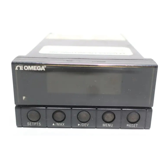
SECTION 5. PARTS OF THE METER 5.1 FRONT OF THE METER Figure 5-1 shows each part of the front of the meter. Table 5-1 on the next page gives a brief description of each part. Figure 5-1. Front-Panel Illustration 1 - Setpoint 1 Status 2 - Setpoint 2 Status Table 5-1. - Page 9 Table 5-1. Front-Panel Part Description ITEM DESCRIPTION /MAX BUTTON During the run mode, press the /MAX button to recall the PEAK reading since the last press of the RESET button. To return to the current readings without resetting the PEAK reading, press the /MAX button.
-
Page 10: Rear Of The Meter
5.2 REAR OF THE METER Figure 5-2a and 5-2b shows the connector label mounted at the top of the meter housing. Table 5-2 gives a brief description of each connector at the rear of the meter. Refer to Figure 6-2 for descriptions of different versions. Figure 5-2a. -
Page 11: Rear Connector Description
Table 5-2. Rear Connector Description CONNECTOR DESCRIPTION TB1-1 Setpoint 1: Normally open (N.O.1) connection TB1-2 Setpoint 1: Normally closed (N.C.1) connection TB1-3 Setpoint 1: Common (COM1) connection TB1-4 Setpoint 2: Normally open (N.O.2) connection TB1-5 Setpoint 2: Normally closed (N.C.2) connection TB1-6 Setpoint 2: Common (COM2) connection TB1-7... -
Page 12: Setup
SECTION 6. SETUP 6.1 CONDITIONS REQUIRING DISASSEMBLY You may need to open up the meter for one of the following reasons: • To check or change the 115 or 230 Vac power jumpers. • To install or remove jumpers on the main board. 6.2 DISASSEMBLY Important: Disconnect the power supply before proceeding. -
Page 13: Main Board Jumpers
6.4 MAIN BOARD POWER JUMPERS (Continued) Figure 6-1 shows the W1 through W3 jumpers on the main board. Figure 6-1. Main Board Power Jumpers (W1, W2, W3) 6.5 MAIN BOARD JUMPERS Figure 6-2 Main board jumpers and Version #1 and Version #2 connectors. TB3A TB3B TB3A... -
Page 14: Jumper Functions
6.5 MAIN BOARD JUMPERS (Continued) S2 jumpers are used for sensor break indications (refer to Table 6-1). S3 jumpers are used for the following (refer to Table 6-1): To enable or disable the front panel push-buttons To allow for an extremely low resistance load for analog output To disable the MENU button To perform calibration procedure Test pins TP1 - TP11 are for testing purposes. -
Page 15: Panel Mounting
6.6 PANEL MOUNTING CONNECTOR LABEL PRODUCT CASE LABEL GASKET FRONT BEZEL Figure 6-3. Meter - Exploded View PANEL THICKNESS 1. Cut a hole in your panel, as shown in 6,4 (.25) MAX Figure 6-3. For specific dimensions 0,8 (.03) MIN refer to Figure 6-4. -
Page 16: Sec 7 Sensor Input And Main Power Connections
SECTION 7. SENSOR INPUT/ MAIN POWER CONNECTIONS 7.1 SENSOR INPUT CONNECTIONS Figure 7-1 describes how to connect your sensor. The different versions are described in figure 6-2. Figure 7-1. Sensor Input Connection... -
Page 17: Main Power Connections
7.2 MAIN POWER CONNECTIONS Figure 7-2 shows the proper AC power main power connections. WARNING: Do not connect ac power to your meter until you have completed all input and output connections. Failure to do so may result in injury! Figure 7-2. -
Page 18: Analog And Relay Output Connections
7.2 MAIN POWER CONNECTIONS (Continued) Figure 7-3. Main Power Connections - DC 7.3 RELAY AND ANALOG OUTPUT CONNECTIONS If you have purchased a meter with dual or analog relay output, refer to the following drawings for output connections. Figure 7-4. Relay Output Connections... -
Page 19: Relay Output Connections
7.3 RELAY AND ANALOG OUTPUT CONNECTIONS (Continued) 1 2 3 4 5 6 7 8 9 10 11 12 ANALOG ANALOG ANALOG CURRENT VOLTAGE 0-20mA 0-10V dc 4-20mA Figure 7-5. Analog Output Connections 0—20mA 0—10VDC 4—20mA 1 2 3 1 2 3 4 5 6 7 8 9 10 11 12 Figure 7-6. -
Page 20: Isolated Analog Output Upper Board Installation
7.3 RELAY AND ANALOG OUTPUT CONNECTIONS (Continued) Figure 7-7. Isolated Analog Output Upper Board Installation 1 2 3 4 5 6 7 8 9 10 11 12 HOUSING CONNECTOR P/N 9001111-02 CONNECTOR CRIMP CONTACT P/N 9001110 USE 22, 24 OR 26AWG WIRES SUPPLIED BY CUSTOMER OUTPUT Figure 7-8. -
Page 21: Input Type (Inpt)
SECTION 8. INPUT TYPE (INPT) Refer to Table 23-1 for a summary list of menu configuration. To select your appropriate input type signal. 1. Press the MENU button until the meter shows “INPT”. 2. Press the /DEV button. The meter shows one of the following: J.TC - Iron vs. -
Page 22: Reading Configuration ("Rd.cf")
SECTION 10. READING CONFIGURATION ("RD.CF") To determine if your meter shows in °F (Fahrenheit) or °C (Celsius). 1. Press the MENU button until the meter shows “RD.CF”. 2. Press the /DEV button. The meter shows one of the following: “R.1=F” (°F) “R.1=C”... -
Page 23: Setpoint 2 Configuration (S2.Cf)
SECTION 12. SETPOINT 2 CONFIGURATION (S2.CF) Setpoint 2 Configuration (S2.CF) is not active unless your meter has dual relay output capabilities. The LED's will display whether the (S2.CF) is active or not. You may use Setpoint 2 Configuration (S2.CF) for the following: To set the setpoint's active band above or below your chosen value To select whether the setpoint operation is latched or unlatched 1. -
Page 24: Sec 13B Cycle Time (Time)
SECTION 13B. CYCLE TIME (“TIME”) If you have select “S.3=P” in Setpoint 1 Configuration (“S1.CF” refer to Section 11), you may specify a cycle time for the time proportional outputs. 1. Press the MENU button until “TIME” appears. 2. Press the /DEV button. -
Page 25: Output Configuration (Ot.cf)
SECTION 15. OUTPUT CONFIGURATION (OT.CF) Output Configuration is not active unless your meter has analog output capabilities. The menu will display whether analog output is present or not. Use Output Configuration (OT.CF) to select the following: To enable or disable the analog output To determine if the analog output is current or voltage To determine if the analog output is proportional to the display or to the error (the difference between reading and setpoint value) -
Page 26: To Select Analog Output Or Proportional Control
15.3 To Select Analog Output or Proportional Control To determine if the meter is to transmit an analog signal out proportional to your display or proportional to the error (proportional control) (The error is defined as the difference between reading and Setpoint 1 value). If you have selected “S.3=P”... -
Page 27: Proportional Band
SECTION 16. PROPORTIONAL BAND (P.BND) 16.1 SELECTING PROPORTIONAL BAND (P.BND) Proportional Band (P.BND) is not active unless your meter has analog output and relay capabilities. The menu will display whether analog output is present or not. • A proportional controller's output is linearly proportional to the change of the error signal, whenever the signal is within 2 prescribed values (Proportional Band). -
Page 28: Manual Reset (M.rst)
SECTION 16. PROPORTIONAL BAND (P.BND) (Continued) If A is the controller gain the, Max. out - Min. out Proportional Band = CONTROLLER OUT = A* ERROR + OFFSET To select the proportional band for your proportional controller, follow these steps: 1. -
Page 29: Output Scale And Offset (Ot.s.o)
SECTION 18. OUTPUT SCALE AND OFFSET (OT.S.O) Output Scale and Offset (OT.S.O) is not active unless your meter has analog output capabilities. The menu will display whether analog output is present or not. Output Scale and Offset (OT.S.O) scales your analog output to be equal to the meter's display and/or any engineering units you require. -
Page 30: Sec
SECTION 18. OUTPUT SCALE AND OFFSET (OT.S.O) (Continued) 9. Press the /DEV button to scroll to the next digit. 10. Press the MENU button to store your selection. The display shows “RD 2” (Read 2). This is your second point of display reading. 11. -
Page 31: Cold Junction Offset Calibration (C.j.of)
SECTION 19. COLD JUNCTION OFFSET CALIBRATION (C.J.OF) The cold junction offset equals the actual temperature minus the reading temperature. You may compensate for any error due to cold junction on the TC input. You may perform this compensation in any temperature from 0°C to 40°C (or 32°F to 104°F), however we recommend you perform this compensation at 0°C (32°F) for best result. -
Page 32: Lock Out Configuration (Lk.cf)
SECTION 20. LOCK OUT CONFIGURATION (LK.CF) Use Lock Out Configuration (LK.CF) for the following: To enable or disable the RESET button in the run mode. To enable or disable setpoint changes 20.1 To Enable or Disable the RESET button in the Run Mode 1. -
Page 33: Tuning Proportional Controller
SECTION 21. TUNING PROPORTIONAL CONTROLLER The Proportional Controller is not active unless your meter has analog output capabilities. The menu will display whether analog output is present or not. This function allows you to tune your controller provided you have analog output capabilities. Select either Time Proportional Control or Analog and Proportional Control. -
Page 34: Display Messages
SECTION 22. DISPLAY MESSAGES Table 22-1. Display Messages MESSAGE DESCRIPTION Hard (power on) Reset INPT Input Type DEC.P Decimal Point RD.CF Reading Configuration S1.CF Setpoint 1 Configuration S2.CF Setpoint 2 Configuration S1.DB Setpoint 1 Deadband TIME Cycle Time for Time Proportional Controller S2.DB Setpoint 2 Deadband OT.CF... -
Page 35: Menu Configuration
SECTION 23. MENU CONFIGURATION Not all menu items display on standard meters. Table 23-1. Configuration Menu (Defaults in Bold and Italics) /DEV /MAX MENU INPT Show input choices: J.TC Iron vs. Constantan Input Type (NIST) K.TC Chromel vs. Alumel (NIST) DJ.TC Iron vs. - Page 36 SECTION 23. MENU CONFIGURATION (Continued) Table 23-1. Configuration Menu (Continued) (Defaults in Bold and Italics) /DEV /MAX MENU OT.CF D: Disabled Output Configuration E: Enabled Analog Output V: Voltage analog out C: Current analog out A: Retransmission of temperature P: Proportional to the error between display reading and D: Proportional analog output is direct reading...
- Page 37 SECTION 23. MENU CONFIGURATION (Continued) Table 23-1. Configuration Menu (Continued) (Defaults in Bold and Italics) /DEV /MAX MENU OT.S.O Show Output Scale & Offset “RD 1” & prior value Enter new value Scroll right one digit Change flashing digit's value &...
-
Page 38: Run Mode Displays
SECTION 23. MENU CONFIGURATION (Continued) Table 23-2. Run Mode Displays RESET DISPLAY /DEV /MAX DESCRIPTION PEAK Shows peak Reset peak Shows highest reading reading since last reset Peak reading. when in this Reading Press again to mode. return to the normal operating mode without... -
Page 39: Setpoint Configuration Displays
SECTION 24. SETPOINT CONFIGURATION DISPLAYS Table 24-1. Setpoint Configuration Displays Table 24-1. Setpoint Configuration Displays MENU /DEV /MAX DESCRIPTION SP 1 Scroll right one Change the flashing Select from Setpoint 1 digit digit’s value -1999 through 9999 SP 2 Scroll right one Change the Select from -1999 through Setpoint 2... -
Page 40: Specifications
SECTION 25. SPECIFICATIONS SIGNAL INPUT Thermocouple Types J - Iron vs. Constantan (NIST) Temperature Ranges -210° through 760°C (-346° through 1400°F) K - Chromel vs. Alumel (NIST) -270° through 1372°C (-454° through 2500°F) DIN J - Iron vs. Constantan (DIN) -200°... - Page 41 SECTION 25. SPECIFICATIONS (Continued) ACCURACY AT 25°C ±0.5°C Temperature Stability 0.04°C/°C Step Response Time 1 seconds Warm Up to Rated Accuracy 30 min ANALOG OUTPUT (if applicable) Signal Type Current or voltage Signal Level Current 10 V max compliance at 20 mA output Signal Level Voltage 20 mA max for 0-10 V output Function...
- Page 42 SECTION 25. SPECIFICATIONS (Continued) INPUT POWER INFORMATION ~ AC units 115/230 V~(AC) ±10%, 50/60 Hz 7 W max, power consumption (Non-Isolated Analog Output) 8 W max, power consumption (Isolated Analog Output) DC units 10-32 Vdc 6 W max, power consumption (Non-Isolated Analog Output) 7 W max, power consumption (Isolated Analog Output) External Fuse Protection Recommended: 115 V...
-
Page 43: Meter Dimensions
SECTION 25. SPECIFICATIONS (Continued) 48,0 (1.89) 96,0 (3.78) FRONT BEZEL 20,3 (.80) RETAINER CASE REAR COVER TOP VIEW SIDE VIEW PANEL THICKNESS 6,4 (.25) MAX 0,8 (.03) MIN (.06) 45,00 + 0,61/-0,00 (1.772 + .024/–.000) 4 PLCS 92,00 + 0,81/–0,00 (3.622 + .032/–.000) NOTE: Dimensions in Millimeters (Inches) Figure 25-1 Meter Dimensions... -
Page 44: Factory Preset Values
SECTION 26. FACTORY PRESET VALUES Table 26-1. Factory Preset Values MENU ITEM FACTORY PRESET VALUES INPT Input Type: K.TC (Type K T/C) DEC.P Decimal Point Position: FFFF. RD.CF Reading Configuration: R.1=F (Fahrenheit) S1.CF Setpoint 1 Configuration: S.1=A (Setpoint is active above) S.2=U (Setpoint is unlatched) S.3=O (On/Off control) S2.CF... -
Page 45: Approvals Information
APPROVALS INFORMATION This product conforms to the EMC directive 89/336/EEC amended by 93/68/EEC, and with the European Low Voltage Directive 72/23/EEC. Electrical Safety EN61010-1:2001 Safety requirements for electrical equipment for measurement, control and laboratory. Double Insulation Pollution Degree 2 Dielectric withstand Test per 1 min •... - Page 46 NOTES...
- Page 47 Authorized Return (AR) number immediately upon phone or written request. Upon examination by OMEGA, if the unit is found to be defective, it will be repaired or replaced at no charge. OMEGA’s WARRANTY does not apply to defects resulting from any action of the purchaser, including but not limited to mishandling, improper interfacing, operation outside of design limits, improper repair, or unauthorized modification.
- Page 48 Where Do I Find Everything I Need for Process Measurement and Control? OMEGA…Of Course! Shop on line at www.omega.com TEMPERATURE Thermocouple, RTD & Thermistor Probes, Connectors, Panels & Assemblies Wire: Thermocouple, RTD & Thermistor Calibrators & Ice Point References Recorders, Controllers & Process Monitors...
Need help?
Do you have a question about the CN1001-TC and is the answer not in the manual?
Questions and answers