Table of Contents
Advertisement
SERVICE
OVEN
Refer to the service manual in the GSPN(see rear cover) for the more information.
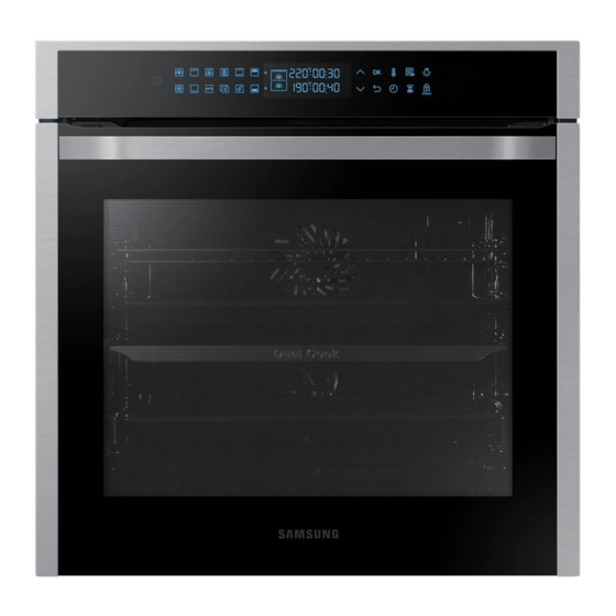
OVEN
BASIC
: NV75N7570RS
MODEL
: NV75N7546RB
MODEL CODE : NV75N7546RB,
NV75N7546RS
Manual
CONTENTS
1. Precaution
2. Product Specification
3. Disassembly and Reassembly
4. Troubleshooting
5. Wiring Diagrams
6. PCB Diagrams
Advertisement
Table of Contents


Need help?
Do you have a question about the NV75N7570RS and is the answer not in the manual?
Questions and answers