
Related Manuals for Kenwood CS-4125


Summary of Contents for Kenwood CS-4125
- Page 1 20MHz DUAL T R A C E OSCILLOSCOPE CS-4125 40MHz DUAL T R A C E OSCILLOSCOPE CS-4135 INSTRUCTION MANUAL KENWOOD CORPORATION ©B63-0302-08 96/12 11 10 9 8 7 6 5 4 3 2...
-
Page 2: S A F E T Y
S A F E T Y S y m b o l i n T h i s M a n u a l A T h i s symbol indicates where applicable cautionary or other information i s to be found. - Page 3 S I C H E R H E I T S y m b o l i n dieser A n l e i t u n g A Dieses S y m b o l Zeigt a n , wo Sicherheitshinweise und andere w i c h t i g e I n f o r - mationen z u finden s i n d .
-
Page 4: Table Of Contents
C O N T E N T S S A F E T Y S A F E T Y A N D E Q U I P M E N T P R O T E C T I O N P R E C A U T I O N S F E A T U R E S P R E F A C E •... -
Page 5: S A F E T Y A N D E Q U I P M E N T P R O T E C T I O N P R E C A U T I O N S
S A F E T Y A N D E Q U I P M E N T P R O T E C T I O N P R E C A U T I O N S C h e c k your line voltage before use. T h e oscilloscope voltage r a t i n g appears on the back of the set. -
Page 6: C H E C K I N G A N D A D J U S T M E N T ' S P R I O R T O M E A S U R E M E N
I n order to prevent the C R T ' s fluorescent screen from scorching, do adjust the brightness higher than necessary and do not leave the spotting function on for long periods of t i m e . T h e set has been equipped w i t h handle, so that you c a n position i t i n either horizontal or diagonal positions. -
Page 7: F E A T U R E S
F E A T U R E S • H i g h S e n s i t i v i t y : S e n s i t i v i t y as 1 m V / d i v . •... -
Page 8: Preface
PREFACE T h i s m a n u a l describes the functions and operations of the C S - 4 1 3 5 and C S - 4 1 2 5 . Most descriptions about the panels and operations are common to these models. -
Page 9: Panel Explanation
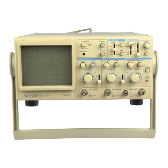
PANEL EXPLANATION F i g u r e 1 . F r o n t Panel F R O N T P A N E L C a t h o d e R a y T u b e ( C R T ) ( 1 ) T h e effective display screen surface r u n s over a n area of eight 1cm d i v i - sions along the v e r t i c a l a x i s and ten 1cm divisions along the horizontal... - Page 10 I n s u c h a case, c a r r y out adjustment a g a i n . T R A C E R O T A C o n t r o l F o r adjusting the slope of the horizontal trace line. T h e slope of the line w i l l change due to s u c h influences as the e a r t h ' s magnetic force.
- Page 11 A P O S I T I O N C o n t r o l (14) F o r adjusting the v e r t i c a l position of the C H 2 w a v e f o r m w h e n displayed on the C R T screen.
- Page 12 C I I 2 I N V S w i t c h (20) When the button is pushed a l l the w a y i n , the polarity of the C H 2 input signal display w i l l be inverted. X - Y Oscilloscope S e t t i n g S w i t c h (21) theBJalfflSl...
- Page 13 L I N E '• T h e c o m m e r c i a l - u s e power source voltage w a v e f o r m w i l l become the trigger s i g n a l source. E X T : T h e signal being input into the E X T .
-
Page 14: R E A R P A N E L
F i g u r e 2. R e a r Panel R E A R P A N E L Z . A X I S I N P U T J a c k (31) Input j a c k for intensity modulation of C R T electron beam. P o s i t i v e voltage decreaces intensity. -
Page 15: U S E O F H A N D L E
| U S E O F H A N D L E 1 E x p a n d the portion © of the handle to both sides, and t u r n the handle to the intended position. M a k e sure that the handle is locked securely before use. C a r r y i n g Position and (3) : T i l t position ®... - Page 16 CHECKING AND ADJUSTMENT PRIOR TO MEASUREMENT I n order to operate the oscilloscope at its optimum performance level, c a r r y out following checks and adjustment before doing your measurements. T h e instructions w h i c h follow concerning basic operation techniques and applications assume that the checks and adjustment described here have been completed.
- Page 17 P l u g the probe into the I N P U T j a c k s of each channel. Set the A C - G N D - D C thetfiWtWMllllMODE control at D C and control at C H I . P l u g the C H I probe to the C A L t e r m i n a l and set the V O L T S / D I V control at 2 0 m V / D I V .
-
Page 18: S I N G L E T R A C E Operation
O P E R A T I N G P R O C E D U R E S S I N G L E T R A C E OPERATION A l t e r n a t i n g C u r r e n t D i s p l a y W i t h the oscilloscope i n the i n i t i a l setting condition (refer to Section 5 of C H E C K - I N G A N D A D J U S T M E N T P R I O R T O M E A S U R E M E N T ) , display on the C R T... -
Page 19: Composite Video S I G N A L Display
Composite V i d e o S i g n a l D i s p l a y When inputting composite video signals, set the [ T R I G G E R I N G ] M O D E to either T V - F R A M E or T V - L I N E . -
Page 20: External Trigger
External Trigger Set the Source control at E X T and apply a s i g n a l to the E X T . T R I G t e r m i n a l . I t i s necessary that this s i g n a l have a fixed t i m i n g relationship to either C H I or C H 2 . -
Page 21: A P P L I C A T I O N S
A P P L I C A T I O N S Because both the v e r t i c a l and horizontal a x i s of the oscilloscope are calibrated, the oscilloscope i s capable of not only d i s p l a y i n g w a v e f o r m s but c a n also q u a n t i t a - t i v e l y m e a s u r i n g voltage or t i m e . -
Page 22: Common-Mode Rejection
E X A M P L E I n F i g u r e 9, the v e r t i c a l distance between the two points i s 4.4 d i v . I f the V O L T S / D I V control i s set at 0 . -
Page 23: M E A S U R I N G D I R E C T Current ( D C ) Voltage
Measuring (DC) Voltage D i r e c t C u r r e n t T h e oscilloscope's v e r t i c a l amplification i s provided b y a direct c u r r e n t amplifier c i r c u i t characterized b y excellent s t a b i l i t y . -
Page 24: M E A S U R I N G S I G N A L W I T H L O W Frequency Components
M e a s u r i n g S i g n a l s w i t h L o w F r e q u e n c y Components When the oscilloscope's A C - G N D - D C control is set at A C , there i s a chance that errors m a y occur i n the voltage measurement. -
Page 25: M E A S U R I N G T I M E Between T W O Points
M e a s u r i n g T i m e B e t w e e n T w o P o i n t s When m e a s u r i n g time between two points, measurements c a n be determined from S W E E P T I M E / D I V and horizontal distance. -
Page 26: M E A S U R I N G Frequencies
M e a s u r i n g F r e q u e n c i e s Since the frequency i s found as a reciprocal of a period, measure time (period) of one cycle and calculate its reciprocal v a l v e . Measure the time of one cycle Calculate the reciprocal value of the period found. -
Page 27: F U S E R E P L A C E M E N T
M A I N T E M A N C E I W A R M N G ) Before performing the following procedures, a l w a y s unplug the power cord. F U S E R E P L A C E M E N T I f the fuse blows, the oscilloscope w i l l not operate. -
Page 28: C L E A N I N G
C L E A N I N G T h e panel, knobs, cover and other parts of this oscilloscope w i l l become d i r t y a s this oscilloscope i s used for long. When they become d i r t y , clean them as s h o w n below. -
Page 29: S P E C I F I C A T I O N S
S P E C I F I C A T I O N S CS-4135 I T E M CS-4125 C R T : Rectangular with internal graticule Type : Approx. 12 kV Acceleration Voltage: Approx. 2 kV Display Area :... - Page 30 I T E M CS-4125 CS-4135 SWEEP S Y S T E M : NORM : Triggered sweep Sweep Modes : Sweep Modes : AUTO : Auto free run with no signal input 0.5 u s/div to 0.5 s/div ±3%, 0.5 a s/div to 0.5 s/div + 3 % ,...
- Page 31 CS-4135 I T E M CS-4125 T r i g g e r S e n s i t i v i t y : C S - 4 1 2 5 SOURCE SIGNAL FREQ. SIGNAL FREQ. MODE MODE E X T...
- Page 32 I T E M CS-4125 CS-4135 ENVIRONMENTAL : Indoor Use Only Altitude up to 2000 m OVER VOLTAGE CATEGORY I I POLLUTION D E G R E E 2 L I N E V O L T A G E / F R E Q U E N C Y :...
-
Page 33: Optional Equipment
OPTIONAL EQUIPMENT T h e oscilloscope offers an optional accessory bag. T h i s bag attaches to the top side of the oscilloscope housing and provides a storage space for two probes a n d the instruction m a n u a l . I n s t a l l the probe pouch as follows: How to Attach the Accessory Bag(MC-78) U n s n a p the probe pouch from the retainer plate. - Page 34 KENWOOD CORPORATION 14-6 Dogenzaka 1-chome, Shibuya-Ku, Tokyo 150.Japan...
Need help?
Do you have a question about the CS-4125 and is the answer not in the manual?
Questions and answers