Advertisement
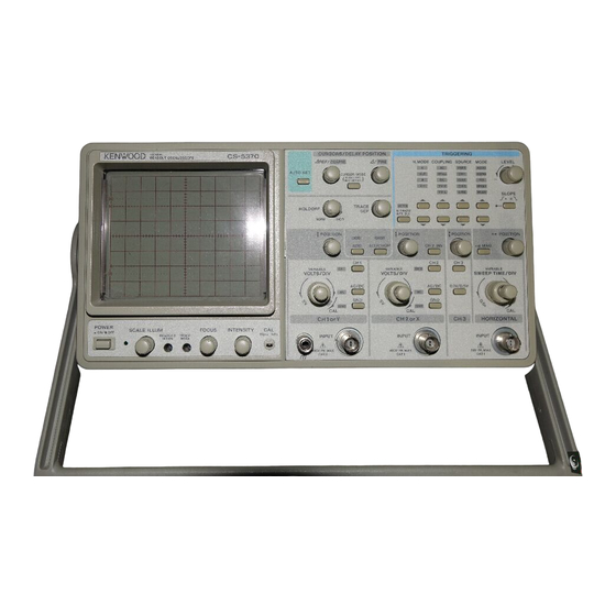
100MHz READOUT OSCILLOSCOPE
S/NO. 2100001~
CS-5350/CS-5370
SERVICE MANUAL
Model No. plate
Filter
(CS-5350 ; B73-0190-04)
(B11-0518-04)
(CS-5370 ; B73-0188-04)
100MHz
READOUT OSCILLOSCOPE
POWER
SCALE ILLUM
_
—
ON/
OFF
Push SW
Decorative panel ; small
(K24-3005-04)
(A21-2468-04)
Handle
(K01-0561-02)
Z AXIS INPUT
42V PK MAX
KENWOOD T M I CORPORATION
Rubber foot
(J02-0540-05)
CS—5370
AUTO SET
HOLDOFF
VOLTS/DIV
FOCUS
INTENSITY
CAL
1Vp-p 1KHz
READOUT
TRACE
INTEN
ROTA
Knob
(Small ; K21-0919-14)
(Large ; K21-0920-04)
AC selector
(E68-0619-05)
CHI OUTPUT
MAX 5V RMS
MADE IN JAPAN
KENWOOD TMI CORPORATION
© 1999-12/B51-1153-00 (K/K)
Decorative panel ; large
(A21-2466-03)
CURSORS/DELAY POSITION
TRIGGERING
REF/
COARSE
/
FINE
H.MODE
COUPLING SOURCE
AC
A
ALT
HF
CURSOR MODE
REJ
PUSH 1 SEC
B
DC
R/O OFF-ON
X-Y
TV-F
TV-L
TRACE
AFT.D
SEP
B TRIG'D
AFT.DLY
NORM
INCR
POSITION
POSITION
POSITION
ADD
CHOP
ADD
ALT/CHOP
CH 2 INV
CH1
CH1
CH 3
CH1
CH2
VARIABLE
VARIABLE
VOLTS/DIV
AC/DC
AC/DC
0.1V/0.5V
AC
AC
GND
GND
GND
GND
CAL
CAL
CH 1or Y
CH 2 or X
CH 3
INPUT
INPUT
400V PK MAX
400V PK MAX
CAT 1
CAT 1
Knob
(K29-0896-04)
Rear panel
(A83-0107-12)
CAUTION
TO AVOID ELECTRIC SHOCK THE POWER
CORD PROTECTIVE GROUNDING CONDUCTOR
MUST BE CONNECTED TO GROUND.
FOR CONTINUED PROTECTION AGAINST FIRE,
REPLACE ONLY WITH FUSE OF THE SPECIFIED
VOLTAGE AND CURRENT RATINGS.
DISCONNECT POWER SUPPLY BEFORE REPLACING FUSE.
DO NOT REMOVE COVER.
REFER SERVICING TO QUALIFIED PERSONNEL.
100
SELECTOR ~LINE VOLTAGE FUSE 250V
100
100V
T 1.0A
120V
120
220
220V
T 400mA
230V
230
Knob
(K29-0877-04)
MODE
LEVEL
VERT
AUTO
CH 1
NORM
—
+
CH 2
FIX
CH 3
SINGLE
LINE
READY
SLOPE
2
3
POSITION
MAG
X10
VARIABLE
SWEEP TIME/DIV
CAL
HORIZONTAL
INPUT
50V PK MAX
CAT 1
Mold panel
(A63-0110-01)
Cord wrap
(W01-0503-04)
Advertisement
Table of Contents

Related Manuals for Kenwood CS-5370


Summarization of Contents
Oscilloscope Performance Specifications
CRT and Vertical Axis Specifications
Details on CRT performance, vertical axis sensitivity, impedance, and frequency response.
Horizontal Axis and Sweep Specifications
Specifications for horizontal axis sensitivity, sweep time, and magnification.
Triggering System Specifications
Trigger modes, coupling, sources, and sensitivity for stable signal triggering.
Operational and Physical Specifications
Power Supply and Consumption
Voltage requirements, power consumption, and operational frequency.
Dimensions, Weight, and Environment
Physical size, weight, operating temperature, and humidity limits.
Readout and Measurement Features
Specifications for display modes, cursor functions, and auto measurements.
Safety, Handling, and Maintenance
Electrical Safety and Power Cords
Guidelines for safe power connection, voltage conversion, and cord usage.
Calibration and Adjustment Procedures
Steps and equipment needed for periodic calibration and optimal performance.
Parts and Diagram References
Complete Parts List
Detailed listing of all components, part numbers, and descriptions for the CS-5350.
Disassembly and Schematic Diagrams
Visual guide for component removal and overall system wiring.
PC Board Component Layouts
Component Placement Diagrams
Visual representation of component placement on key PC boards.
Semiconductor Information
Semiconductor Identification and Pinouts
Diagrams and pin configurations for integrated circuits and transistors.
Need help?
Do you have a question about the CS-5370 and is the answer not in the manual?
Questions and answers