Table of Contents
Advertisement
Advertisement
Table of Contents

Subscribe to Our Youtube Channel
Related Manuals for Landis+Gyr FOCUS KWH


Summary of Contents for Landis+Gyr FOCUS KWH
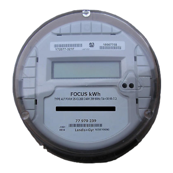
- Page 1 FOCUS kWh Solid-State Meter Technical Manual Bulletin 160 Revision 2.1...
- Page 2 Information in this document is subject to change without notice. No part of this document may be reproduced or transmitted in any form or by any means, electronic or mechanical, for any purpose without the express written permission of Landis+Gyr, Inc.. © 2003 Landis+Gyr, Inc.
-
Page 3: Table Of Contents
TABLE OF CONTENTS ..........................URPOSE ........................ARGET ROUP ........................ONDITIONS ......................AFETY ARNINGS ....................UBLISHED PECIFICATIONS (IEEE) ..........NSTITUTE FOR LECTRICAL AND LECTRONIC NGINEERS (ANSI) ............... MERICAN ATIONAL TANDARDS NSTITUTE (UL)..................NDERWRITERS ABORATORIES ....................ANADIAN PECIFICATIONS FCC I : ......................NFORMATION FOCUS .................. - Page 4 4.1.3......................11 OCKET BASE 4.1.4........................ 12 ................13 VERVIEW OF LECTRONIC ARDWARE 5.1.1. LCD D ....................... 13 ISPLAY 5.1.2. : ................... 13 ISPLAY CROLL EQUENCE 5.1.3....................14 ISPLAY ORMAT 5.1.4..................14 IGITAL OWER NDICATOR 5.1.5................. 14 OWER ISPLAY EQUENCE...
- Page 5 2: D ................... 19 IFFERENTIAL ULSE ................... 20 RODUCT PECIFICATIONS ....................20 ENERAL PECIFICATIONS ......................20 OWER ONSUMPTION ........................... 20 URDEN ........................ 20 TARTING ..........................20 ORMS ....................20 PERATING EMPERATURE ....................... 20 CCURACY LASS ......................20 ISPLAY PTIONS AMR P ........................
- Page 6 14 – F 25S......................9 IGURE 15 – F 2K ....................... 10 IGURE 16 – F 3S......................10 IGURE 17 – F 4S......................10 IGURE 18 – L .................. 13 IGURE IQUID RYSTAL ISPLAY 19 – C LED L ................17 IGURE ALIBRATION OCATION...
-
Page 7: Conditions
Failure to comply with these precautions or with specific warnings elsewhere in this manual violates safety standards of design, manufacture, and the intended use of the metering instrument. Landis+Gyr, Inc. assumes no liability for the customer's failure to comply with these requirements. -
Page 8: Underwriters Laboratories
American National Standards Institute (ANSI) • American National Standard Code for Electricity Metering, ANSI C12.1-2001 • American National Standard for Watt-Hour Meters, ANSI C12.10-1997 • American National Standard Method of Salt Spray (Fog) Testing, ANSI/ASTM B117-73, (Z 118.1-1974) • American National Standard for Electricity Meters 0.2 and 0.5 Accuracy Classes, ANSI C12.20- 1998 Underwriters Laboratories (UL) •... - Page 9 (3) For RF exposure, service personnel are to maintain a minimum of 20cm from the RF communications transmitter once installed. Changes or modifications not expressly approved by Landis+Gyr could void the user’s authority to operate the equipment. Do not change the original antenna without pre-approval from the original meter manufacturer.
-
Page 10: Introduction T O The Baseplate Assembly
FOCUS Introduction To The FOCUS meter was designed to be a low-cost, solid-state, kWh-only meter as an alternative metering and AMR platform to the induction meter. The meter is based on reliable, field proven digital multiplication measurement technique. The meter platform will measure energy accurately over varying environmental conditions. -
Page 11: Figure 3 - Meter Assemblye
Figure 3 - Meter Assembly Exploded View The Focus meter is composed of three basic sub-assemblies: The baseplate assembly, the electronics housing assembly and the meter cover. The electronics housing assembly snaps onto the baseplate and creates a weatherproof seal when the cover is installed. The cover includes an emboss to align an optical probe for register configuration purposes. -
Page 12: Electronic Housing Assembly
Electronic Housing Assembly Figure 5 - Electronics Housing Assembly Exploded View The Electronics Housing contains the measurement board and any optional electronics assemblies such as option boards or communication devices. It also contains the liquid crystal display (LCD) on which meter readings and other pertinent data can be displayed. -
Page 13: The Focus Meterf
AMR packages. Any of these can be factory installed or conveniently added to the meter in the field. Register Types The Focus kWh is an active energy “kWh-only” meter. It is capable of measuring and displaying kilowatt-hours delivered to and received from a load. -
Page 14: Meter Assembly
Meter Assembly Removal of the Electronics Housing from the Baseplate In rare instances, it may be necessary to access the inner electronics of the Focus meter. To remove the Electronics Housing from the baseplate, set meter on a solid surface and place hands around the bottom of the gray housing where it meets with the baseplate. - Page 15 FOCUS can be installed through the cover and baseplate assembly.
-
Page 16: Figure 8 - Unused T-Seals
Figure 8 – Unused T-Seals Figure 9 – Formed T-Seal After Installation Figure 10 – T-Seal Installed Each T-seal is installed by fully inserting it through the cover and through the baseplate assembly. Bend the T-seal tab to prevent extraction. Next, bend the T-seal over so that it resides within the baseplate assembly pocket. -
Page 17: Application Information
Application Information Available Meter Forms FOCUS is available in the following meter forms: 4.1.1. S-Base • Transformer rated: Class 10 & 20: 3S, 4S • Self-contained: class 100: 1S • Self-contained: class 200: 2S, 12S and 25S (Network) • Self-contained: class 320: 2SE 4.1.2. -
Page 18: Figure 14 - Form 25S
Figure 12 – Form 2S, 2SE Table 2 - Form 2S/2SE Specifications Form Class Test Amps Volts Wire Figure 13 – Form 12S (Network) Figure 14 – Form 25S (Network) -
Page 19: Figure 15 - Form 2K
Table 3 - Form 12S/25S Specifications Form Class Test Amps Volts Wire 120/208 14.4 120/208 14.4 Figure 15 – Form 2K Table 4 - Form 2K Specifications Form Class Test Amps Volts Wire 14.4 14.4 Transformer Rated Meter Forms Figure 16 – Form 3S Table 5 - Form 3S Specifications Form Class... -
Page 20: Installation Procedures
Table 6 - Form 4S Specifications Form Class Test Amps Volts Wire The form 3S features a movable fifth terminal that can be located in the 3 o’clock or 6 o’clock centered locations. Forms 12S and 25S (Network) feature a movable fifth terminal that can be located in the 3 o’clock, 6 o’clock centered, or 6 o’clock offset locations. -
Page 21: K-Base
4.1.4. K-Base 1). Compare the wiring with diagrams of Section 3.2 to made sure the meter is wired properly. 2). Install the meter on the studs in the K-mounting device. 3). Tighten down nuts securely to torque requirements listed inside the socket. 4). -
Page 22: Overview Of Electronic Hardware
Overview of Electronic Hardware Delete “Optical” below 5.1.1. LCD Display Figure 18 – Liquid Crystal Display kWh FOCUS LCD shows the digital power indicator, nominal service voltage and various selectable metrics. 5.1.2. Display Scroll Sequence: Focus Configuration The display scroll sequence is programmable at the factory or by the user with Tool . -
Page 23: Display Format
5.1.5. Power Up Display Sequence All Focus kWh display segments, including the DPI segments, illuminate after the meter is powered up regardless of the display sequence program. This segment check display persists for less than five seconds upon meter power-up, after which time the display begins its programmed scroll sequence. -
Page 24: Diagnostics/Error Codes
Diagnostics/Error Codes 5.1.6. Meter Errors The following table contains the meter errors available for display in the diagnostic status word. Meter Errors Error Codes Unprogrammed 000001 Configuration Error 000010 Self Check (microprocessor status) 000100 RAM Error 001000 Nonvolatile Memory Error (EEPROM) 010000 Measurement Error 100000... -
Page 25: Configuring The Meter
Configuring the Meter 6.1. Configuration Port The ability to configure the meter is provided through a secure meter configuration port. A cover mounted optical configuration port accommodates meter configuration by the user. The configuration port is designed to be used in a meter shop ambient environment, requiring that it function in a room temperature environment under room ambient lighting conditions. -
Page 26: Meter Calibration
7.1.1. Calibration LED The Focus kWh has an infrared light emitting diode (LED) that emits energy pulses. The calibration LED is deactivated 24 hours after the meter powers up. Once reactivated (recycle power), the calibration LED remains active for 24 hours. -
Page 27: Factory Calibration
7.1.3. Customer Calibration Adjustment Focus kWh calibration is adjustable by the user. Individual element FL calibration biases up to 1.00% in increments of 0.05% are provided by means of a calibration utility and the configuration port. The factory FL series (and individual element, when applicable) calibration value cannot be altered by user calibration adjustment. -
Page 28: Pulse Outputs
Pulse Outputs Pulse Initiator Output The Focus kWh offers one optional solid-state KYZ output. The solid-state pulse initiator output emits pulses in accordance with +kWh, -kWh or added kWh as configured by the user. The pulse output- scaling factor is programmable by the user. Each KYZ output relay is assigned an independent Ke constant that represents the quantity of energy for the output pulse. -
Page 29: Product Specifications
Product Specifications General Specifications • Active Energy “kWh-Only” meter • Digital Multiplication Measurement Technique • Non-Volatile Memory • Designed for 15+ year life Power Consumption • Digital Power Indicator (DPI) Burden • Burden < 1.8 Watts Starting Load • Starting Load 50 mA or 12 Watts Forms •... - Page 30 • Selectable meter multiplier up to 240 (1200:5 CT) • Operating Voltage Range (value)
Need help?
Do you have a question about the FOCUS KWH and is the answer not in the manual?
Questions and answers