
Related Manuals for Landis+Gyr E220 3 Series


Summary of Contents for Landis+Gyr E220 3 Series
- Page 1 Electricity meters MID Residential E220‐AMxD E220 Series 3 User manual Date: 12.05.2022 Filename: D000070822 E220‐AMxD Series 3 User manual en f.docx © Landis+Gyr D000070822 en f ...
- Page 2 Revision history Version Date Comments a 14.06.2021 First release. Editorial corrections. b 16.12.2021 Wireless M‐Bus rate use cases added. Updated sections for product safety and temperature ranges. c 19.01.2022 Updated screw head type. d 02.03.2022 Updated with aluminium wire compatible option e 05.04.2022 Updated type designation. f 12.05.2022 Updated cover picture and other pictures. Although the information contained within this document are presented in good faith and believed to be correct, Landis+Gyr (including its affiliates, agents and employees) disclaim any and all liability for any errors, inaccuracies or incompleteness relating to the product. Landis+Gyr makes no warranty, representation or guarantee regarding the performance, quality, durability or suitability of the products for any particular purpose. To the fullest extent permitted by law Landis+Gyr disclaims (1) any and all liability arising out of the use of the product, (2) any and all liability, including, but without limitation to, special, consequential and indirect damages and losses, and (3) any and all implied warranties, including, but without limitation to, fitness for purpose and merchantability. The information contained in this document is strictly confidential and is intended for the addressee only. The unauthorised use, disclosure, copying, alteration or distribution of this document or the contents thereof is strictly prohibited and may be unlawful. All product information are subject to change without notice. © Landis+Gyr D000070822 en f – E220 Series 3 – E220‐AMxD – User manual ...
-
Page 3: Table Of Contents
Meter configuration .......................... 2 6 5.3.1 Mechanical variants .......................... 2 6 5.3.2 Faceplate ............................ 2 7 5.3.3 Firmware parameters ........................ 2 7 5.3.4 Logistics ............................. 2 8 End‐user operations .......................... 2 8 5.4.1 User menu ............................ 2 8 5.4.2 Optical interface: INFO DSS ...................... 3 3 D000070822 en f – E220 Series 3 – E220‐AMxD – User manual © Landis+Gyr ... - Page 4 General .............................. 3 4 5.6.2 Dual rate module .......................... 3 4 5.6.3 RS‐485 LMN interface ........................ 3 6 5.6.4 Wireless M‐Bus LMN interface ...................... 3 7 Maintenance ............................ 38 Service .............................. 3 8 Troubleshooting ............................ 3 8 6.2.1 Error codes ............................ 3 8 Decommissioning and disposal ...................... 39 Terms and abbreviations ........................ 40 Index .............................. 41 © Landis+Gyr D000070822 en f – E220 Series 3 – E220‐AMxD – User manual ...
- Page 5 Provision of knowledge concerning the characteristics, construction and function of the meters Information about potential dangers, their consequences and measures to prevent any danger Details about the performance of all activities throughout the service life of the meters (parameterisation, installation, commissioning, operation, maintenance, decommissioning and disposal) Target group The content of this user manual is intended for technically qualified personnel of energy supply companies, responsible for system planning, installation and commissioning, operation, maintenance, decommissioning and disposal of meters. Reference documents The following documents provide further information related to the subject of this document: D000070821 E220‐AMxD Series 3 Technical data en Typographical The following typographical conventions are used in this document: conventions Font Description Bold Font style used for menu items and buttons in the user interface and for keyboard keys. Italics Font style used for captions and new terminology. Courier Font for file names, paths and code examples. Terms and abbreviations A list of terms and abbreviations used in this document is available at the end of this document. D000070822 en f – E220 Series 3 – E220‐AMxD – User manual © Landis+Gyr ...
-
Page 6: Safety And Regulations
Used to indicate a dangerous situation that could cause bodily injury or death. Caution Used to indicate a situation/ action that could result in material damage or loss of data. Note Used to indicate general guidelines and other useful information. In addition to the danger level, safety information also describes the type and source of the danger, its possible consequences and measures for avoiding the danger. Responsibilities The owner of the meters – usually the utility company – is responsible for assuring that all persons engaged in working with meters: Have read and understood the relevant sections of the user manual. Are appropriately qualified for the work to be performed. Strictly observe the safety regulations (laid down in section 1.3 “Safety regulations”) and the operating instructions as specified in the individual sections. In particular, the owner of the meters bears responsibility for the protection of persons, prevention of material damage and the training of personnel. For this purpose, Landis+Gyr provides training on a variety of products and solutions. Contact your local Landis+Gyr representative for more information. Safety regulations The following safety regulations must be observed at all times: The meter connections must be disconnected from all voltage sources during installation or when opening. Contact with live parts can be fatal. The main fuses should, therefore, be removed and kept in a safe place until the work is completed so that other persons cannot replace them unnoticed. © Landis+Gyr D000070822 en f – E220 Series 3 – E220‐AMxD – User manual ... -
Page 7: Measurement Accuracy Remarks
Safety and regulations 7/42 Local safety regulations must be observed. Only technically qualified and appropriately trained personnel are authorised to install the meters. Only appropriate tools shall be used for the job. This means, e.g. that the screwdriver must be of the correct size for the screws, and the handle of the screwdriver must be insulated. The meters must be held securely during installation. They can cause injuries if dropped. Meters that have been dropped must not be installed, even if no damage is apparent, but must be returned to the service and repair department (or the manufacturer) for testing. Internal damage may result in malfunctions or short‐circuits. The meters must never be cleaned under running water or with compressed air. Water ingress can cause short‐circuits. Measurement accuracy remarks For the devices described here, the MessEV §17, paragraph (4) applies. Note When connected to a Smart Meter Gateway, values measured with the meter may only be used for billing purposes, if the voltage supply of the Smart Meter Gateway conforming to the MessEV is obtained from an unmetered area. Note Historical energy registers and instantaneous values are provided exclusively for information purposes and may not be used for billing. D000070822 en f – E220 Series 3 – E220‐AMxD – User manual © Landis+Gyr ... -
Page 8: Description Of Unit
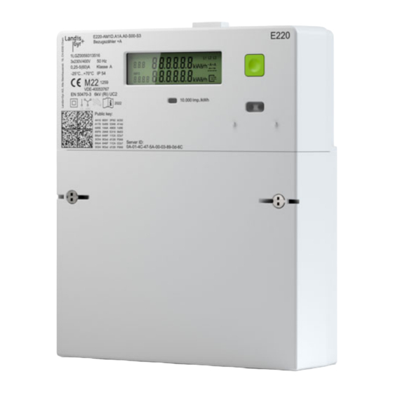
Figure 1. General view of the device Functional overview The E220 is a standalone meter (“modern Messeinrichtung”) according to the German Digitisation Act. It was designed close to the FNN specification for base meters. In the module slot you can install one of several different dual rate modules, an RS‐485 LMN interface or a wireless M‐Bus LMN interface for communication with a Smart Meter Gateway and to be integrated into an intelligent Metering System (iMsys). The E220 is available in the following meter variant: E220‐AM1D 60 A meter E220‐AM1D 60 A meter with aluminium compatible clamps The meter can be configured to one of the following measurement modes during the manufacturing process: +A with return stop Active plus only ‐A with return stop Active minus only +A / ‐A Active plus and active minus ‐A balanced without return stop Active totalised © Landis+Gyr D000070822 en f – E220 Series 3 – E220‐AMxD – User manual ... -
Page 9: Technical Overview
IEC 62052‐11 Product safety Protection class IEC 62052‐11 II Overvoltage category IEC 62052‐31 III Rated impulse voltage IEC 62052‐31 6 kV Utilisation category IEC 62052‐31 UC2 Extended environmental conditions 3K6 Pollution degree 2 Operating altitude < 2,000 m Insulation L1 – L2 – L3 – N Reinforced 6 kV L1+L2+L3+N – LMN Reinforced 6 kV L1+L2+L3+N – Rate input Reinforced 6 kV Rate input: Clamping of overvoltage 2 kV D000070822 en f – E220 Series 3 – E220‐AMxD – User manual © Landis+Gyr ... -
Page 10: Type Designation
0 Optional B RS‐485 module C Wireless M‐Bus module Hardware series S1 Series 1 S2 Series 2 S3 Series 3 A3 Series 3 with aluminium wire compatible terminals © Landis+Gyr D000070822 en f – E220 Series 3 – E220‐AMxD – User manual ... -
Page 11: Technical Details
2.5.1 Overview Architectural overview Figure 2. Architectural overview Measurement technology The measurement technology used in the E220 meters is based on current shunts. Three measuring elements (one for each phase) measure the phase currents using shunts, and the phase voltages over resistor dividers. The analogue/digital converters transform both signals into digital voltage and current data. This data is then fed into the microprocessor, which produces the energy proportional values and adds the value to the corresponding values of the other phases. The sum is then transferred into the corresponding energy registers. Power supply The supply voltage for the meter electronics is taken from the three‐phase system. The meter will work correctly as soon as neutral and at least one phase are connected to mains voltage. In the event of mains failure, a voltage monitor ensures the safe storage of meter data and manages the restart when mains voltage is restored. Auxiliary power supply The auxiliary power terminal (L3) can be used supply external devices installed on or close to the meter. The auxiliary voltage output is tapped in the unfused and unmetered area. Auxiliary power supply Reference current 1.6 A Nominal voltage 230 VAC D000070822 en f – E220 Series 3 – E220‐AMxD – User manual © Landis+Gyr ... -
Page 12: Push Button
Summation method Vector summation for 3‐phase 4‐wire summation over all phases is done as follows: Calculation Example 1 Example 2 method +A with return stop ‐A with return stop +A / ‐A ‐A balanced without return stop 2.5.2 Push button INFO interface is used to communicate with the meter. The meter is set to the menu mode using the push button. 2.5.3 Optical input Optical INFO interface is used to communicate with the meter. The meter is set to the menu mode using a flashlight. © Landis+Gyr D000070822 en f – E220 Series 3 – E220‐AMxD – User manual ... -
Page 13: Optical Output (Info Interface)
Description of unit 13/42 The illuminance of the flashlight must be at least 400 lux. 2.5.4 Optical output (INFO interface) The E220 has a unidirectional optical interface. It is designed according to the DIN EN 62056‐21 standard. The meter pushes a defined set of values every second to the optical interface. D000070822 en f – E220 Series 3 – E220‐AMxD – User manual © Landis+Gyr ... -
Page 14: Mechanical Construction
4 2 3 5 6 Figure 3. Meter case 1 Position for flexible hook (rear side) 2 LCD display 3 Pulse output LED (metrological LED) 4 Push button 5 Optical interface 6 Terminal cover © Landis+Gyr D000070822 en f – E220 Series 3 – E220‐AMxD – User manual ... -
Page 15: Faceplate Markings
8 CE conformity, metrological approval, EU type examination certificate 9 German national type approval certificate (only relevant with the LMN module plugged‐in) 10 Rated impulse voltage and utilization category 11 Symbols: Isolation Measurement mode Calibrated single‐phase meter Calibrated three‐phase meter Read User Manual Year of calibration 12 Manufacturer address 13 2‐D barcode including: manufacturer serial number, device ID, server ID, public key 14 Public key NIST curve 15 Server ID 16 Property plate 17 Impulse constant of pulse output LED 18 Connection diagram D000070822 en f – E220 Series 3 – E220‐AMxD – User manual © Landis+Gyr ... -
Page 16: Control Elements
16/42 Mechanical construction Control elements The E220 meter has as two control elements, the push button and the optical interface. These interfaces are used by the end‐user to communicate with the device. Dimensions Connections 3.5.1 E220 60A direct connected Terminal type Cage clamp terminal Diameter 7.3 mm Maximum wire diameter (Cu) 7.0 mm Minimum wire diameter (Cu) 1.5 mm Cable cross sections (solid wires only) 1.5 to 25 mm² Screw head Pozidriv no. 2 PlusMinus Tightening torque (using cables) 2.0 – 3.0 Nm Flexible wires must always be fitted with ferrules. A meter variant with aluminium compatible clamps for installations in locations with aluminium wiring is available. © Landis+Gyr D000070822 en f – E220 Series 3 – E220‐AMxD – User manual ... -
Page 17: Auxiliary Voltage Connections
Mechanical construction 17/42 3.5.2 Auxiliary voltage connections The meter has auxiliary voltage terminals to supply external devices with power. Terminal type Cage‐clamp terminal Diameter 3.0 mm Screw head Pozidriv no. 1 Connection diagrams According to the German standard DIN 43856, connection and circuit diagrams are labelled with numbers. Direct connected meters Direct connected (4‐wire) meters are connected as follows (use in 1‐wire 2‐phase networks is permitted on phases L1, L2 and L3). Figure 5. DIN 43856 Electricity meters, rate time switches and ripple control receivers. Diagram number 4000 D000070822 en f – E220 Series 3 – E220‐AMxD – User manual © Landis+Gyr ... -
Page 18: Installation
The meter is intended to be installed indoors in non‐condensing humidity conditions. The meter should be installed with copper conductors. The use of aluminium conductors is only supported with the aluminium conductor compatible variant. For installation, flexible wires with ferrules may be used. The installation site must meet the requirements of: The meter’s ingress protection rating (IP54), The specified operating temperature range (‐25 °C … +70 °C) and The specified limit operating temperature range (‐40 °C … +70 °C). Avoid installing the meter on south‐facing walls and in direct sunlight. If necessary, use an additional shield or visor to protect the installation from direct sunlight (shield not provided by Landis+Gyr). This meter is intended for indoor use only In cases where an outdoor installation is unavoidable, care must be taken to ensure the meter is installed within a suitable enclosure to maintain the operating environment in accordance with the meter specification. Such enclosures must be securely sealed to avoid the risk of meter damage as a consequence of exposure to the external environment including (but not limited to) extreme temperatures, humidity and insect ingress. Introduction The following conditions must be met for installation and commissioning of the meter: The work described below must only be conducted by technically qualified and suitably trained persons. These persons must be familiar with and observe the local safety regulations. ... -
Page 19: Before Installation
The installer is responsible for coordinating the rating and the characteristics of the supply side overcurrent protection devices with the maximum current rating and, in the case of direct connected meters, with the utilisation category rating of the metering equipment. Before installation Dangerous voltage on conductors The connecting wires at the place of installation must not be live when fitting the meter. Touching live parts is dangerous to life. The main fuse should be removed and kept in a safe place until work is completed, so that it cannot be replaced by anyone unnoticed. No overcurrent protection or automatic disconnection As the meter has no internal overcurrent protection and no method of disconnection from the mains, this must be provided by the end installation. Mounting Observe safety instructions Prior to starting the mounting of the meter, read and strictly observe the general safety instructions given in section 4.2 “Before installation”. Observe E VDE‐AR‐N 4101:2014‐03 Requirements for metering points in electrical installations in the low voltage network. The meter should be mounted as follows on the meter board or similar device provided for this purpose (see also section 3.4 “Dimensions”): Find the correct position for the meter. Make sure there are no wires underneath the holes to be drilled. Determine the desired type of mounting (open or covered mounting). For covered mounting, use the fixed bracket at the back of the meter. For open mounting, move the mounting bracket (provided with the unit) to the top of the meter. See the following figure. D000070822 en f – E220 Series 3 – E220‐AMxD – User manual © Landis+Gyr ... -
Page 20: Connecting
20/42 Installation Figure 6. Mounting bracket location at the back of the meter (standard terminal cover) Connecting Before putting the meter into operation, the following items must be checked and corrected, if necessary: Has the correct meter (with correct identification number) been installed at the measuring point of the relevant consumer? Are all thrust screws for the phase connections and neutral tightened sufficiently? Are the mains inputs and outputs connected correctly? The conductor from the house connection or from the main fuse must be present at the input, those of the meter to the consumer at the output. Is the neutral conductor connected to terminal 10? Attach the terminal cover. Close the terminal cover with screws. Check the installation as described in section 0 “ During installation the oxidation layer on the stripped cable ends must be removed. The use of oxidation inhibiting compound, according to the manufacturer’s instructions, is recommended. Commissioning and functional check”. 4.4.1 Aluminium conductors © Landis+Gyr D000070822 en f – E220 Series 3 – E220‐AMxD – User manual ... -
Page 21: Commissioning And Functional Check
Preparation Aluminium conductors require appropriate preparation of the wires prior to connection. During installation the oxidation layer on the stripped cable ends must be removed. The use of oxidation inhibiting compound, according to the manufacturer’s instructions, is recommended. Commissioning and functional check The installed meter should be checked and put into service as follows: Insert the main fuses removed before installation. The meter is switched on. After 2 seconds, the display lights up with the display test. It shows all segments of the upper line and the lower line for 2 seconds each. This sequence is repeated three times. The upper line shows the OBIS code 0.2.0 for firmware version, the lower line shows the firmware version. The upper line shows the OBIS code C.90.2 for firmware checksum, the lower line shows the firmware checksum. Check the display for error messages and connect a load. Check that the meter is measuring correctly. Display indicators and their functions are described in section 5.1 “Display”. Uninstalling the meter Remove main fuse before disconnecting The connecting wires at the place of installation must not be live when removing the meter. Touching live parts is dangerous to life. The corresponding main fuse must be removed and kept in a safe place until work is completed, so that it cannot be replaced by anyone unnoticed. Remove the meter from the mains network as follows: Switch off the voltage by detaching the main fuse. The display goes off. Remove the seals from terminal cover screws. Release and remove the terminal cover. Ensure with a phase checker that the connecting wires have no voltage. If there is voltage, remove the main fuses. D000070822 en f – E220 Series 3 – E220‐AMxD – User manual © Landis+Gyr ... - Page 22 22/42 Installation Remove the connecting wires of the auxiliary inputs and outputs, if available. Loosen the terminal screws of the phase and neutral connecting wires with a suitable screwdriver and withdraw the wires from the terminals. Unscrew and remove the meter. Fix a replacement meter with the three fixing screws on the mounting surface. Connect the replacement meter as described in section 4.4 “Connecting” and the following sections. © Landis+Gyr D000070822 en f – E220 Series 3 – E220‐AMxD – User manual ...
-
Page 23: Operation
Status information: 4 Phase voltage presence indications 5 Energy direction 6 Simulation of rotating disk 7 Status of LMN communication (only relevant with optional RS‐485 LMN interface) Information display: 8 Measurement units 9 Value field 10 OBIS code 11 Info for running pushes on optical INFO interface 5.1.2 Billing‐relevant line The following tables show a list of commonly used OBIS codes. The display list of the E220 meter depends on the measurement mode. +A with return stop (Einrichtungszähler +A) Upper line OBIS code Value F.F. Error code (see section 6.2.1 “Error codes”) 1.8.0 Active energy +A (import), total ‐A with return stop (Einrichtungszähler –A) Upper line OBIS code Value F.F. Error code (see 6.2.1 “Error codes”) 2.8.0 Active energy ‐A (export), total D000070822 en f – E220 Series 3 – E220‐AMxD – User manual © Landis+Gyr ... -
Page 24: Status Information On The Display
Value F.F. Error code (see section 6.2.1 “Error codes”) 2.8.0 Active energy ‐A (export), total 5.1.3 Status information on the display Phase voltage presence indications If phase L1, L2 or L3 is present, the corresponding segment lights up. The threshold is 0.8 U . Energy direction ‐A or +A represents the actual energy direction. An additional arrow below the corresponding A symbol is also lit. Simulation of rotating disk The four horizontal bars simulate the rotating disk of Ferraris meters. The disk always runs left to right regardless of the energy direction. With each pulse of the pulse output LED (metrological LED), the rotating disk switches to the next segment. Terminal cover detection The INFO symbol on the display is blinking 2s on / 1s off as long as the terminal cover is missing or not fitted properly. If the terminal cover is removed whilst the meter is powered, the activation of the tamper flag is not delayed. The delayed activation of the tamper flag does not affect the blinking of the INFO symbol on meter display. Status of LMN communication This symbol is only relevant with the LMN module plugged‐in. The symbol represents the different statuses of the LMN interface: Symbol Status OFF No communication on the LMN interface. Blinking Any layer 2 telegrams detected. 0.5 s on/0.5 s off Blinking HDLC connection telegrams detected. 2 s on/ 2 s off © Landis+Gyr D000070822 en f – E220 Series 3 – E220‐AMxD – User manual ... -
Page 25: Information Display Line
TLS connection ready. The meter communicates in secure mode. 5.1.4 Information display line Measurement units Lower line OBIS‐Code Value P Instantaneous power balance +A – ‐A (if enabled) Value field and OBIS code Field for displaying instantaneous power and to provide information about installed LMN or Dual Rate module according to the following table. Code Installed module LMN LMN RS‐485 module Mbus Wireless M‐Bus module TA B2T/L2T 230 V (x.8.1) module TB B2T/L2T 230 V (x.8.2) module TC B2T/L1T 230 V (1.8.1) module TD B2T/L1T 230 V (1.8.2) module Module codes are displayed in the OBIS code area of the display. Info for running pushes on optical INFO interface The INFO symbol indicates to the end‐user that the second line is for information purposes only. It also indicates data pushes on the optical INFO interface. Faceplate description Device ID The Device ID is a unique identifier according to the DIN 43863‐5 standard. The 14 characters are defined as follows: D000070822 en f – E220 Series 3 – E220‐AMxD – User manual © Landis+Gyr ... -
Page 26: Meter Configuration
Characters 2 to 4 represent the manufacturer. In our case “LGZ”. Manufacturer block is “00”. The last 8 characters are the manufacturer serial number. 2D barcode The 2D barcode is generated according to ISO/IEC 16022:2000 and ISO/IEC 24720:2006. The 2D barcode includes: Prefix AA: Device ID Prefix AB: Server ID Prefix AC: Public key See also FNN document “Data Matrix Code für Messeinrichtungen und Komponenten für Messsysteme”. Server ID At the optical INFO interface, data is pushed in SML (Smart Message Language). The server ID is part of the SML response. The server ID is derived out of the device ID. Public key NIST curve TLS communication on LMN requires the NIST curve. The public key of the meter is printed on the faceplate. Meter configuration The initial configuration of the meter is defined when ordering the meter from Landis+Gyr. 5.3.1 Mechanical variants Parameter Values E220 – 60A, 0.25‐5 (60) A Meter variants RS‐485 LMN interface pre‐installed Module slot Wireless M‐Bus LMN interface pre‐installed Dual rate module pre‐installed © Landis+Gyr D000070822 en f – E220 Series 3 – E220‐AMxD – User manual ... -
Page 27: Faceplate
Not shown in the 2nd line Active power Shown in the 2nd line Save end‐user data protection settings at power‐down End‐user settings at power‐down Reset data protection settings at power‐down The tamper detection status bit is set when the Status bit for tamper detection terminal cover is opened. when opening Optionally, and on customer request, activation of the the terminal bit may be delayed after voltage application (between cover 0 min and 60 min in 5 min increments) to suppress activation upon installation of the meter. This parameter is selectable at the time of ordering and cannot be changed after production. The default value is 0 min Module detection The module code is displayed in the OBIS code field for 30 minutes after the meter is powered up and the terminal cover is removed. When the terminal cover is installed, the code display disappears. After the new removal of the terminal cover, the module OBIS code is again displayed for 30 minutes or until the terminal cover is re‐installed. D000070822 en f – E220 Series 3 – E220‐AMxD – User manual © Landis+Gyr ... -
Page 28: Logistics
Display test Upper line Lower line PIn Enter the PIN code P Instantaneous power E Total energy since last reset 1d Energy (consumption/generation) last day 7d Energy (consumption/generation) last 7 days (week) 30d Energy (consumption/generation) last 30 days (month) 365d Energy (consumption/generation) last 365 days (year) HIS Reset historical values InF Push reduced data set or extended data set PIn Activate/deactivate PIN code Note Historical energy registers and instantaneous values are provided exclusively for information purposes and may not be used for billing. Optical interface The optical interface has two functions: Short flash from a flashlight (shorter than 2 seconds) Long flash from a flashlight (longer than 5 seconds) After a period of 120 seconds without any action on the optical interface, the meter will fall back to the standard display (rolling list in case two energy registers are available). © Landis+Gyr D000070822 en f – E220 Series 3 – E220‐AMxD – User manual ... - Page 29 - 7 4 0 - - ==== Pulse Lower P I n Increment +1 After 3 sec. L1 L2 L3 8 8 8 8.8.8 Upper 8.8.8 <-A +A> Flash INFO ==== - 7 4 8 0 - Pulse Lower P I n Increment +1 After 3 sec. PIN correct? D000070822 en f – E220 Series 3 – E220‐AMxD – User manual © Landis+Gyr ...
- Page 30 Upper 8.8.8 <-A +A> Pulse INFO C L r ==== Short Lower 8.8.E Pulse After 120 sec. To Rolling List Reset Temporary Values Values since last zeroing L1 L2 L3 8 8 8 8.8.8 Upper 1.8.0 <-A +A> INFO 3 2 1.4 ==== Lower 8.8.1 d © Landis+Gyr D000070822 en f – E220 Series 3 – E220‐AMxD – User manual ...
- Page 31 Operation 31/42 5.4.1.4 Historical values With short flashes, the menu switches to the next current values. With long flashes, the menu switches to historical values. D000070822 en f – E220 Series 3 – E220‐AMxD – User manual © Landis+Gyr ...
- Page 32 <-A +A> Pulse INFO ==== Short Lower I.n.F Pulse After 120 sec. To Rolling List Toggle on/oFF L1 L2 L3 8 8 8 8.8.8 Long Upper 8.8.8 <-A +A> Pulse INFO ==== Short Lower P.I.n Pulse After 120 sec. To Rolling List Toggle on/oFF To Rolling List On: Extended data set Off: Reduced data set © Landis+Gyr D000070822 en f – E220 Series 3 – E220‐AMxD – User manual ...
-
Page 33: Optical Interface: Info Dss
To Rolling List Toggle on/oFF To Rolling List On: PIN activated, instantaneous power not displayed on lower line. Off: PIN disabled, instantaneous power displayed, if enabled. 5.4.2 Optical interface: INFO DSS Data pushes The optical INFO interface operates in two modes: standard and extended. It pushes the following data periodically every second. Manufacturer identification Device identification Meter reading for +A (if present) Meter reading for ‐A (if present) Instantaneous power (if activated) Communication parameters The communication channel has the following parameters: Bitrate 9600 Baud Code 8‐N‐1 Update 5.5.1 Crypto reset The command “Reset cryptographic parameters” will reset E220 meters to the customer‐specific default values with regard to these parameters. The command can be only executed when the LMN module is plugged‐in to the RS‐485 interface. This reset causes the following actions to be performed in the E220 meter: The symmetrical key for the exchange of TLS certificates is set to the delivery state (the register “Operational key” is thereby set to “Initial key”). D000070822 en f – E220 Series 3 – E220‐AMxD – User manual © Landis+Gyr ... -
Page 34: Firmware Update
All TLS certificates and temporary TLS properties including session keys are explicitly headed by ‘0x00…00’. The transmission counter (see FNN LMN requirements for symmetric encryption for the exchange of TLS certificates) will not be reset. The state “Operation in a secured SMGw environment” is disabled. The command “Reset cryptographic parameters” can only be executed, if certain conditions are fulfilled. The time “Tclosed” must be set to 30 seconds. 5.5.2 Firmware update Firmware updates are not possible. Optional modules 5.6.1 General The E220 meter has a module slot above the terminal block. In a standard delivery, the module slot is covered with a dummy cover. In this case, the meter operates as a standalone 1 rate meter. Change modules in power OFF mode only To install or replace a module, always disconnect the meter from power. 5.6.2 Dual rate module To plug in the dual rate module to the E220, the power must be switched off. After power‐up, the meter switches to the dual rate mode. As soon as the meter operates in dual rate mode, it writes to registers x.8.1 and x.8.2. The corresponding registers in the rolling list are displayed on the display with the appropriate OBIS code (see also 5.1.1 “Basic layout and symbols”). The OBIS code of the respective active register flashes (0.25 s off / 0.75 s on). In the background, register x.8.0 continues to grow as the sum of x.8.1 and x.8.2. There are four different types of dual rate modules for the control of tariffication. The meter automatically switches to the correct rating variant by means of a predefined PIN code in the module (factory setting). The basic variant of the meter (consumption, generation or bidirectional meter) defines the type of the total registers in the meter (+ A: 1.8.0; ‐A: 2.8.0). The dual rate module can only operate with an existing total register. © Landis+Gyr D000070822 en f – E220 Series 3 – E220‐AMxD – User manual ... - Page 35 Operation 35/42 There are four different variants of the Dual Rate Module: Module type Description Module B2T/L2T Import 2‐rate, export 2‐rate (B2T/L2T); 230 V (x.8.1) = 230 V for 1.8.1 and 2.8.1 = 0 V for 1.8.2 and 2.8.2 Module B2T/L2T Import 2‐rate, export 2‐rate (B2T/L2T); 230 V (x.8.2) = 230 V for 1.8.2 and 2.8.2 = 0 V for 1.8.1 and 2.8.1 Module B2T/L1T Import 2‐rate, export 1‐rate (B2T/L1T); 230 V (1.8.1) = 230 V for 1.8.1 and 2.8.0 = 0 V for 1.8.2 and 2.8.0 D000070822 en f – E220 Series 3 – E220‐AMxD – User manual © Landis+Gyr ...
-
Page 36: Rs-485 Lmn Interface
230 V (2.8.2) = 230 V for 1.8.2 and 2.8.0 = 0 V for 1.8.1 and 2.8.0 5.6.3 RS‐485 LMN interface The Smart Meter Gateway communicates with one or more meters connected to the LMN (Local Measurement Network) to get values. The meters are either wired or wireless connected. Applications at the LMN interface are categorised as follows: LMN meter administration a. Registration / configuration b. Key / certificate management Request and reception of meter values a. Single request for meter values b. Multiple requests for meter values The actual status of LMN communication is shown on the display. The symbol represents the different statuses of the LMN interface: Symbol Status OFF No communication on the LMN interface. Blinking Any layer 2 telegrams detected. 0.5 s on/0.5 s off Blinking HDLC connection telegrams detected. 2 s on/ 2 s off ON TLS connection ready. The meter communicates in secure mode. © Landis+Gyr D000070822 en f – E220 Series 3 – E220‐AMxD – User manual ... -
Page 37: Wireless M-Bus Lmn Interface
Special Application Layer EN 13757‐3 Communication systems for meters and their remote reading ‐ Part 4: Wireless meter reading (radio meter reading between the 868 MHz and 870 MHz SRD band) EN 13757‐4 Communication systems for meters and their remote reading ‐ Part 2: Physical and Link Layer EN 13757‐2 Standard EN 13757‐4, T1 Security profile Encryption mode 7 Frequency 868.95 MHz (minimum 868.7 MHz; maximum 869.2.00 MHz) Transmission power Minimum 3.16 mW (5 dBm) to maximum 25 mW (13.9 dBm) Antenna Internal antenna Range in free field* Up to a maximum of 400 metres Sending interval 16 seconds * May vary depending on terrain and building structure. In combination with a smart meter gateway, the following rate use cases (TAF) are supported according to PTB 50.8: Rate use case Description TAF1 Data saving rates TAF2 Time‐variable rates (rate switching ≥ 1 hour) TAF6 Retrieval of measured values in case of need D000070822 en f – E220 Series 3 – E220‐AMxD – User manual © Landis+Gyr ... -
Page 38: Maintenance
38/42 Maintenance Maintenance Service The E220 meter has no serviceable parts. Device service is available from the local Landis+Gyr representative. Troubleshooting If the meter is not operating correctly, check the error displays and LED (see section 5.1 “Display” for instructions on how to use the display). If there is a problem with meter operation, the following points should be checked first: Is the mains voltage present (check meter display)? Has the maximum operating temperature been exceeded? Is the meter visibly damaged? Is there any error code on the display (code F.F.)? The error codes are described in section 6.2.1 “Error codes”. 6.2.1 Error codes Critical Error A critical error means that a legally relevant function is no longer working properly. Values may not be used for billing without validation. Critical errors indicate severe problems, but the device can still operate. However, the data measured and stored in the meter may be corrupted and it is recommended that meters showing critical errors are returned to the designated Landis+Gyr service centre. If the device is displaying the F.F. register with an error code, there is a critical error. If the error register is not cleared, the failure code can be viewed in the installation/service menu or by reading the F.F. register through the communications interface. Critical errors can only be cleared via communication with a reset command. Due to the temporary nature of communication errors they do not cause the F.F. register to be displayed. However, communication errors get stored in the error register. They are cleared when communication is restored. Communication errors do not usually require meter replacement. These errors do not cause the F.F register to be automatically shown on the display, but are stored in the error register. The meter continues normal operation and does not usually have to be replaced. ... -
Page 39: Decommissioning And Disposal
Decommissioning and disposal 39/42 Decommissioning and disposal Electronic waste treatment This product must not be disposed of in regular waste. Use a professional electronic waste treatment process. The components used to manufacture the device can, in the main, be broken down into constituent parts and sent to an appropriate recycling or disposal facility. When the product is removed from use, the whole product must be sent to a professional electronic waste treatment process. The waste treatment and disposal plants must be approved by local regulatory authorities. The end processing of the product and recycling of its components must always be carried out in accordance with the rules and regulations of the country where the end processing and recycling are done. On request, Landis+Gyr will provide more information about the environmental impact of the product. Disposal and environmental protection regulations The following are general guidelines and should not take priority over local disposal and environmental policies, which should be adhered to without compromise. Components Disposal Printed circuit boards Delivered to recycling plants Metal components Sorted and delivered to metal recycling plants Plastic components Sorted and delivered to re‐granulation if at all possible D000070822 en f – E220 Series 3 – E220‐AMxD – User manual © Landis+Gyr ... -
Page 40: Terms And Abbreviations
Optical INFO interface is a standardised interface for the end‐user. It is used to communicate with the base meter. LCD Liquid Crystal Display. LED Light‐Emitting Diode. LMN Local Metrological Network. LMN provides the communication network between the meter and the gateway. Typically an RS‐485 or wireless M‐Bus interface. MCU Microcontroller Unit. A single computer chip designed for embedded applications. NIST National Institute of Standards and Technology. NIST has endorsed elliptic curve cryptography in its set of recommended algorithms for key exchange and digital signature. OBIS Object Identification System. OBIS provides standard identifiers for all data within the metering equipment, both measurement values and abstract values. PIN Personal Identification Number. PIN is a code asked by the SIM card to authenticate the user. RAM Random Access Memory. RLM Registered Power Measurement. SLP Standard Load Profile. SMGw Smart Meter Gateway. SML Smart Message Language. SML is a communication protocol for electricity meters. TLS Transport Layer Security. TLS is a cryptographic protocol that provides communications security over a computer network. © Landis+Gyr D000070822 en f – E220 Series 3 – E220‐AMxD – User manual ... -
Page 41: Index
Regulations ............ 6 Environmental protection regulations .... 39 Responsibilities .......... 6 Functional overview .......... 8 Target group of this manual ........ 5 General view ............ 8 Technical details ............ 1 1 Installation ............ 18 Terms .............. 4 0 Maintenance ............ 38 Type designation ........... 1 0 Mechanical construction ........ 14 Typographical conventions ........ 5 Operation.............. 23 D000070822 en f – E220 Series 3 – E220‐AMxD – User manual © Landis+Gyr ... - Page 42 Contact: Landis+Gyr AG Alte Steinhauserstrasse 18 CH‐6330 Cham Switzerland Phone: +41 41 935 6000 www.landisgyr.com ...
Need help?
Do you have a question about the E220 3 Series and is the answer not in the manual?
Questions and answers