Table of Contents
Advertisement
Quick Links
INSTALLATION AND MAINTENANCE INSTRUCTIONS
M500SAP Supervised Control Module
SPECIFICATIONS
Normal Operating Voltage:
Maximum Alarm Current:
Average Operating Current:
Maximum NAC Line Loss:
External Supply Voltage (between Terminals T3 and T4)
Maximum (NAC):
Maximum (Speakers):
Max. NAC Current Ratings:
Temperature Range:
Humidity:
Dimensions:
Accessories:
UL864 listed
RELAY CONTACT RATINGS
CURRENT RATING
2 A
3 A
2 A
0.46 A
0.7 A
0.9 A
0.5 A
0.3 A
All relay switch contacts are shipped in the standby (open) state, but may have transferred to the activated (closed) state during shipping. To ensure that the
switch contacts are in their correct state, modules must be made to communicate with the panel before connecting circuits controlled by the module.
BEFORE INSTALLING
This information is included as a quick reference installation guide. Refer to
the control panel installation manual for detailed system information. If the
modules will be installed in an existing operational system, inform the opera-
tor and local authority that the system will be temporarily out of service. Dis-
connect power to the control panel before installing the modules.
NOTICE: This manual should be left with the owner/user of this equipment.
GENERAL DESCRIPTION
M500SAP Supervised Control Modules are intended for use in intelligent, two-
wire systems, where the individual address of each module is selected using
the built-in rotary decade switches. This module is used to switch an external
power supply, which can be a DC power supply or an audio amplifier (up
to 80 VRMS), to notification appliances. It also supervises the wiring to the
connected loads and reports their status to the panel as NORMAL, OPEN, or
SHORT CIRCUIT. The M500SAP has two pairs of output termination points
available for fault-tolerant wiring and a panel-controlled LED indicator.
COMPATIBILITY REQUIREMENTS
To ensure proper operation, these modules shall be connected to listed com-
patible system control panels only.
MOUNTING
The M500SAP mounts directly to 4-inch square electrical boxes (see Figure 2A).
The box must have a minimum depth of 2
cal boxes (SMB500-WH) are available from System Sensor.
15 to 32 VDC
6.5mA (LED On)
400 µA max., 1 communication every 5 seconds 47k EOL resistor, 485 uA max.(Communicating, NAC shorted).
4 VDC
Regulated 24VDC
70.07 V RMS, 50 W
For class B wiring system, the current rating is 3A; For class A wiring system, the current rating is 2A
32˚F to 120˚F (0˚C to 49˚C)
10% to 93% Non-condensing
4.67˝ H x 4.26˝ W x 1.40˝ D (118.62 mm H x 108.20 mm W x 35.56 mm D)
Mounts to a 4˝ square (10.16 cm) by 2
SMB500-WH Electrical Box; CB500 Module Barrier
MAXIMUM VOLTAGE
25 VAC
30 VDC
30 VDC
30 VDC
70.7 VAC
125 VDC
125 VAC
125 VAC
1
/
inches. Surface mounted electri-
8
1
/
˝(5.4 cm) deep box.
8
LOAD DESCRIPTION
PF = 0.35
Resistive
Resistive
(L/R = 20ms)
PF = 0.35
Resistive
PF = 0.75
PF = 0.35
WARNING
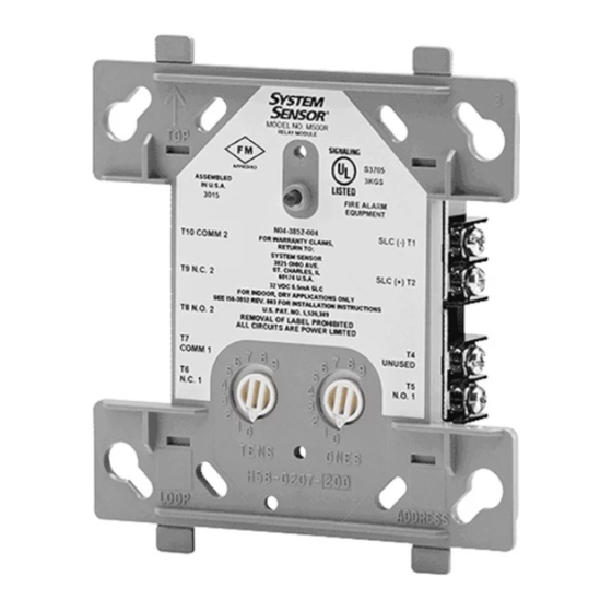
FIGURE 1A. CONTROLS AND
INDICATORS
WIRING
NOTE: All wiring must conform to applicable local codes, ordinances, and reg-
ulations. When using control modules in nonpower limited applications, the
System Sensor CB500 Module Barrier must be used to meet UL requirements
for the separation of power-limited and nonpower-limited terminals and wir-
ing. The barrier must be inserted into a 4˝×4˝×2
control module must be placed into the barrier and attached to the junction
box (Figure 2A). The power-limited wiring must be placed into the isolated
quadrant of the module barrier (Figure 2B).
1.
Install module wiring in accordance with the job drawings and appropri-
ate wiring diagrams.
1
3825 Ohio Avenue, Illinois 60174
1-800-SENSOR2, FAX: 630-377-6495
www.systemsensor.com
APPLICATION
Non-coded
Non-coded
Coded
Non-coded
Non-coded
Non-coded
Non-coded
Non-coded
FIGURE 1B. JUMPER LOCATION
J1
C1059-00
1
/
˝ junction box, and the
8
C0910-00
I56-6790-000
8/19/2020
Advertisement
Table of Contents

Related Manuals for System Sensor M500SAP


Summary of Contents for System Sensor M500SAP
- Page 1 The barrier must be inserted into a 4˝×4˝×2 ˝ junction box, and the The M500SAP mounts directly to 4-inch square electrical boxes (see Figure 2A). The box must have a minimum depth of 2 inches. Surface mounted electri- control module must be placed into the barrier and attached to the junction cal boxes (SMB500-WH) are available from System Sensor.
- Page 2 Secure module to electrical box (supplied by installer), as shown in Figure 2A. IMPORTANT: When using the M500SAP for fire fighter telephone applica- tions, remove Jumper (J1) and discard. The Jumper is located on the back as shown in figure 1B. The module does not provide ring back when used as a fire fighter telephone circuit.
- Page 3 FIGURE 4. TYPICAL FAULT TOLERANT NOTIFICATION APPLIANCE CIRCUIT CONFIGURATION, NFPA CLASS A 24 VDC CIRCUIT CONNECT MODULES TO LISTED DO NOT LOOP WIRE ON TERMINALS 10 & 11. COMPATIBLE CONTROL PANELS ONLY BREAK WIRE RUN TO PROVIDE SUPERVISION 24 VDC POWER SUPPLY OF CONNECTIONS.
- Page 4 THREE-YEAR LIMITED WARRANTY System Sensor warrants its enclosed product to be free from defects in materials and TX 79936 USA. Please include a note describing the malfunction and suspected cause of workmanship under normal use and service for a period of three years from date of failure.
Need help?
Do you have a question about the M500SAP and is the answer not in the manual?
Questions and answers