Table of Contents
Advertisement
Quick Links
INSTALLATION AND MAINTENANCE INSTRUCTIONS
M500FP Firephone Control Module
SPECIFICATIONS
Normal Operating Voltage:
Maximum Current Draw:
Average Operating Current:
SLC Wiring Resistance:
Supervisory Wiring Resistance:
Handset Offhook Resistance:
External Supply Voltage (between Terminals T10 and T11)
Temperature Range:
Humidity:
Dimensions:
Accessories:
BEFORE INSTALLING
This information is included as a quick reference installation guide. If the
modules will be installed in an existing operational system, inform the op-
erator and local authority that the system will be temporarily out of service.
Disconnect power to the control panel before installing the modules.
NOTICE: This manual should be left with the owner/user of this equipment.
GENERAL DESCRIPTION
M500FP Firephone Control Modules are intended for use in intelligent, two-
wire systems, where the individual address of each module is selected using
the built-in rotary switches. This module is used to connect a remote fire-
fighter telephone to a centralized telephone console. A ringing sound is pro-
vided at each off-hook handset until it is connected to the console. Wiring to
individual telephone jacks and handsets is supervised, and status is reported
to the panel as NORMAL, TROUBLE, or TELEPHONE. The M500FP has two
pairs of output termination points available for fault-tolerant wiring, and in-
cludes a panel-controlled LED indicator.
COMPATIBILITY REQUIREMENTS
To ensure proper operation, this module shall be connected to Listed compat-
ible system control panels only.
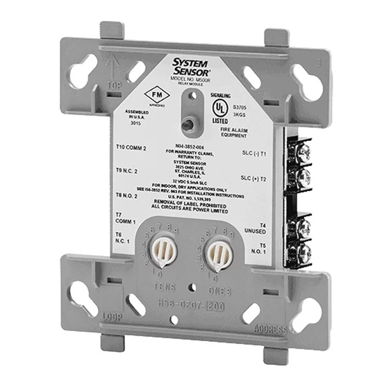
MOUNTING
This module mounts directly to 4" square electrical boxes (see Figure 2A).
The box must have a minimum depth of 2
(SMB500) are available.
WIRING
NOTE: All wiring must conform to applicable local codes, ordinances and
regulations.
1.
Install module wiring in accordance with the job drawings and appropri-
ate wiring diagrams (Figures 3-4).
2.
Set the address on the module per job drawings.
3.
Secure module to electrical box (supplied by installer), as shown in
Figure 2.
15 to 32 VDC
7.5mA (LED on)
2.4mA (LED flashing)
40 Ohms
50 Ohms
400 to 1,500 Ohms
Regulated 24VDC
32˚F to 120˚F (0˚C to 49˚C)
10% to 93% Non-condensing
4.5" H x 4.275" W x 1.4"D (Mounts to a 4" square by 2
SMB500 Electrical Box; CB500 Barrier
". Flush mounted electrical boxes
1
/
8
1
/
" deep box.)
8
FIGURE 1. CONTROLS AND INDICATORS
FIGURE 2. MODULE MOUNTING:
1
3825 Ohio Avenue, St. Charles, Illinois 60174
1-800-SENSOR2, FAX: 630-377-6495
www.systemsensor.com
C1059-02
C1070-03
I56-3870-002
03-11
Advertisement
Table of Contents

Subscribe to Our Youtube Channel
Related Manuals for System Sensor M500FP


Summary of Contents for System Sensor M500FP
- Page 1 Wiring to individual telephone jacks and handsets is supervised, and status is reported to the panel as NORMAL, TROUBLE, or TELEPHONE. The M500FP has two pairs of output termination points available for fault-tolerant wiring, and in- cludes a panel-controlled LED indicator.
- Page 2 C1077-07 THREE-YEAR LIMITED WARRANTY System Sensor warrants its enclosed product to be free from defects in materials and TX 79936 USA. Please include a note describing the malfunction and suspected cause of workmanship under normal use and service for a period of three years from date of failure.
Need help?
Do you have a question about the M500FP and is the answer not in the manual?
Questions and answers