Table of Contents
Advertisement
Quick Links
INSTALLATION AND MAINTENANCE INSTRUCTIONS
M502MA Interface Module
SPECIFICATIONS
Normal Operating Voltage:
Maximum Current Draw:
Average Operating Current:
EOL Resistance:
Maximum IDC Wiring Resistance:
IDC Supply Voltage (between Terminals T10 and T11)
Regulated DC Voltage:
Ripple Voltage:
Alarm Current:
Standby Current:
Temperature Range:
Humidity:
Dimensions:
Accessories:
BEFORE INSTALLING
This information is included as a quick reference installation guide. Refer to the con-
trol panel installation manual for detailed system information. If the modules will be
installed in an existing operational system, inform the operator and local authority
that the system will be temporarily out of service. Disconnect power to the control
panel before installing the modules.
NOTICE: This manual should be left with the owner/user of this equipment.
GENERAL DESCRIPTION
The M502MA Interface Module is intended for use in intelligent, two-wire systems,
where the individual address of each module is selected using the built-in rotary
switches. This module allows intelligent panels to interface and monitor two-wire
conventional smoke detectors. It transmits the status (normal, open, or alarm) of one
full zone of conventional detectors back to the control panel. All two-wire detectors
being monitored must be ULC compatible with this module. The M502MA has a
panel controlled LED indicator. M502MA is capable of handling more than one de-
tector in alarm condition.
COMPATIBILITY REQUIREMENTS
To ensure proper operation, this module shall be connected to a compatible
System Sensor system control panel only (list available from System Sensor).
MOUNTING
The M502MA mounts directly to 4-inch square electrical boxes. (See Figure 2.) The
box must have a minimum depth of 2.125 inches. Surface mounted electrical boxes
(SMB500) are available from System Sensor.
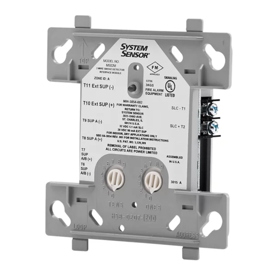
FIGURE 1. CONTROLS AND INDICATORS
15 to 32 VDC
5.1 mA (LED on)
270 µA (LED flashing)
3.9K Ohms
25 Ohms
24 VDC power limited
0.1 Volts RMS maximum
90 mA per module
13 mA Maximum @24 VDC
32˚F to 120˚F (0˚C to 49˚C)
10% to 93% Non-condensing
4.5˝ H × 4˝ W × 1.25˝ D (Mounts to a 4˝ square by 2.125˝ deep box.)
SMB500 Electrical Box
WIRING
NOTE: All wiring must conform to applicable local codes, ordinances, and regula-
tions. This module is intended for power-limited wiring only.
1.
Install module wiring in accordance with the job drawings and appropriate wir-
ing diagrams.
2.
Set the address on the module per job drawings.
3.
Secure module to electrical box supplied by installer. (See Figure 2.)
FIGURE 2. MODULE MOUNTING
C1059-00
1
3333 Unity Drive, Mississauga, ON L5L 3S6
800/736-7672, FAX: 905-812-0771
www.systemsensor.ca
ISOLATED
QUADRANT
I56-1051-002
C1066-00
7/1/2022
Advertisement
Table of Contents

Related Manuals for System Sensor M502MA


Summary of Contents for System Sensor M502MA
- Page 1 It transmits the status (normal, open, or alarm) of one full zone of conventional detectors back to the control panel. All two-wire detectors being monitored must be ULC compatible with this module. The M502MA has a panel controlled LED indicator. M502MA is capable of handling more than one de- tector in alarm condition.
- Page 2 FIGURE 3. INTERFACE TWO-WIRE CONVENTIONAL DETECTORS, NFPA CLASS B FROM OPTIONAL BRANCH CIRCUIT PANEL OR TO NEXT TO NEXT INTERFACE PREVIOUS DEVICE MODULE. MODULE POWER TO THE INTERFACE DEVICE SUPERVISES SUPPLY MODULE MUST BE EXTERNALLY VOLTAGE AND SWITCED TO RESET THE DETECTOR LOOP.
- Page 3 COMPATIBLE TWO-WIRE SYSTEM SENSOR SMOKE DETECTORS FOR USE WITH M502MA WITH ZONE IDENTIFIER A Detector Compatibility Detector Base Base Model Type Model Identifier Detectors 1451A Ionization B401A/BA 2451A Photoelectric B401A/BA 1400A Ionization — 2400A Photoelectric — 1100A Ionization — 1151A...
- Page 4 (3PL), c/o Kuehne and Nagel, 6335 Edwards Blvd., Mississauga, Ontario L5N 2W7, System Sensor warrants its enclosed device to be free from defects in materials and System Sensor warrants its enclosed device to be free from defects in materials and RA #__________.
Need help?
Do you have a question about the M502MA and is the answer not in the manual?
Questions and answers