Table of Contents
Advertisement
Quick Links
INSTALLATION AND MAINTENANCE INSTRUCTIONS
M500RAP Relay Control Module
SPECIFICATIONS
Normal Operating Voltage:
Maximum Current Draw:
Average Operating Current:
EOL Resistance:
Temperature Range:
Humidity:
Dimensions:
Accessories:
NOTE: The control module is manufactured using two configurations. Both variants offer the same functionality. Reference the section of the manual that reflects
the terminal alignment on the module you are using.
RELAY CONTACT RATINGS
CURRENT RATING
2 A
3 A
2 A
0.46 A
0.7 A
0.9 A
0.5 A
0.3 A
BEFORE INSTALLING
This information is included as a quick reference installation guide. Refer to
the control panel installation manual for detailed system information. If the
modules will be installed in an existing operational system, inform the opera-
tor and local authority that the system will be temporarily out of service. Dis-
connect power to the control panel before installing the modules.
NOTICE: This manual should be left with the owner/user of this equipment.
GENERAL DESCRIPTION
The M500RAP Relay Control Module is intended for use in intelligent, two-
wire systems where the individual address of each module is selected using
the built-in rotary switches. It allows a compatible control panel to switch
discrete contacts by code command. The relay contains two isolated sets of
Form-C contacts, which operate as a DPDT switch and are rated in accordance
with the table in the manual. Circuit connections to the relay contacts are
not supervised by the module. The module also has a panel controlled LED
indicator.
COMPATIBILITY REQUIREMENTS
To ensure proper operation, this module shall be connected to a compatible
system control panel only.
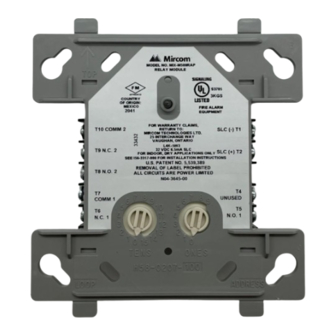
FIGURE 1. CONTROLS, INDICATORS, AND TERMINAL DEFINITIONS
RELAY COMMON 2
NORMALLY CLOSED 2
NORMALLY OPEN 2
RELAY COMMON 1
NORMALLY CLOSED 1
NORMALLY OPEN 1
Note: For legacy terminal designations, see Figure 4.
15 to 32 VDC
6.5 mA (LED on)
230μA direct poll; 255μA group poll
Not used
32˚F to 120˚F (0˚C to 49˚C)
10% to 93% Non-condensing
4.675" H x 4.275" W x 1.4" D (119 mm H x 108 mm W x 36 mm D) (Mounts to a 4" square by 2
SMB500 Series Electrical Box
MAXIMUM VOLTAGE
25 VAC
30 VDC
30 VDC
30 VDC
70.7 VAC
125 VDC
125 VAC
125 VAC
COMMUNICATION
LINE (NEGATIVE)
COMMUNICATION
LINE (POSITIVE)
C2241-01
LOAD DESCRIPTION
PF = 0.35
Resistive
Resistive
(L/R = 20ms)
PF = 0.35
Resistive
PF = 0.75
PF = 0.35
MOUNTING
The M500RAP mounts directly to 4-inch square electrical boxes. (See Figure
2). The box must have a minimum depth of 2
mounted electrical boxes (SMB500-WH) are available from System Sensor.
The module can also mount to the DNR(W) duct housing.
FIGURE 2. MODULE MOUNTING
1
3825 Ohio Avenue, Illinois 60174
1-800-SENSOR2, FAX: 630-377-6495
www.systemsensor.com
1
/
" deep box.)
8
APPLICATION
Non-coded
Non-coded
Coded
Non-coded
Non-coded
Non-coded
Non-coded
Non-coded
1
/
inches (54 mm). Surface
8
C2250-00
I56-6789-001
04/26/2022
Advertisement
Table of Contents

Related Manuals for System Sensor M500RAP


Summary of Contents for System Sensor M500RAP
- Page 1 NOTICE: This manual should be left with the owner/user of this equipment. GENERAL DESCRIPTION The M500RAP Relay Control Module is intended for use in intelligent, two- wire systems where the individual address of each module is selected using the built-in rotary switches. It allows a compatible control panel to switch discrete contacts by code command.
- Page 2 NORMALLY OPEN 1 C1071-01 NOTE: Refer to pages 3 and 4 of this instruction manual for complete information regarding the legacy M500RAP configuration. THREE-YEAR LIMITED WARRANTY System Sensor warrants its enclosed product to be free from defects in materials and TX 79936 USA.
- Page 3 NOTICE: This manual should be left with the owner/user of this equipment. GENERAL DESCRIPTION The M500RAP Relay Control Module is intended for use in intelligent, two- wire systems, where the individual address of each module is selected using the built-in rotary decade switches. It allows a compatible control panel to switch discrete contacts by code command.
- Page 4 C0924-03 THREE-YEAR LIMITED WARRANTY System Sensor warrants its enclosed product to be free from defects in materials and TX 79936 USA. Please include a note describing the malfunction and suspected cause of workmanship under normal use and service for a period of three years from date of failure.
Need help?
Do you have a question about the M500RAP and is the answer not in the manual?
Questions and answers