Table of Contents
Advertisement
Quick Links
Advertisement
Table of Contents

Related Manuals for SGM i-6


Summary of Contents for SGM i-6
- Page 1 USER MANUAL Product Version 1.0 | Document Revision A | Released 2022-4-21...
-
Page 2: I-6 Series Dimensions
All dimensions in millimeters and inches. Drawing not to scale This manual covers installation, use, and maintenance of the SGM i-6 Series. A digital version is available at www.sgmlight.com or upon request via support@sgmlight.com. The information in this document is subject to change without notice. -
Page 3: I-6 Rgbw / I-6 White Poi
RGBW / i-6 WHITE POI 502mm 19,76in 440mm 17,32in 406mm 166mm 15,99in 6,53in 200mm 150mm 5,91in 7,87in 320mm 12,60in 220mm 8,66in 81mm 3,19in 401mm 111mm 15,77in 4,37in 468mm 150mm 18,41in 5,91in 326mm 12,82in 172mm 6,78in All dimensions in millimetres and inches. Drawing not to scale... -
Page 4: Table Of Contents
CONTENT 2 i-6 SERIES DIMENSIONS 2 i-6 RGBW / i-6 White standard 3 i-6 RGBW / i-6 White POI 6 SAFETY INFORMATION 7 BEFORE INSTALLING THIS PRODUCT 8 INSTALLATION STANDARD FIXTURE 8 Identification and terminology 9 Unpacking 9 Application considerations 9 Transport handling 9 Rigging 10 ... - Page 5 32 Supported RDM functions 32 Sensors 33 ACCESSORIES 33 Anti-glare shields 33 MAINTENANCE 33 SGM Vacuum Test kit 34 Firmware Updates 35 Cleaning 35 Maintenance Schedule i-6 35 Maintenance Notes 36 TROUBLESHOOTING 37 FIXTURES AND ACCESSORIES 37 Ordering information 38 SUPPORT HOTLINE 38 APPROVALS AND CERTIFICATIONS 39 USER NOTES Product Version 1.0 | Revision A | Released 2022-4-21...
-
Page 6: Safety Information
WARNING! READ THE FOLLOWING SAFETY PRECAUTIONS CAREFULLY BE- FORE UNPACKING, INSTALLING, POWERING OR OPERATING THE DEVICE. SGM fixtures are intended for professional use only. They are not suitable for household use. Les fixtures SGM sont impropre à l’usage domestique. Uniquement à usage professionnel. -
Page 7: Before Installing This Product
EXTERNAL CLEANING AND VISUAL INSPECTION OF THE FIXTURE All users of the SGM fixtures should regularly clean those parts of the fixture directly exposed to the elements, such as the external housing and front lenses. Additionally, all owners of the SGM fixtures must periodically check the external housing of the fixture for structural breaks, deteri- oration, cracked lenses, or loose screws. -
Page 8: Installation Standard Fixture
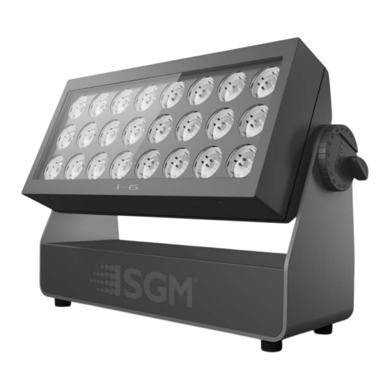
INSTALLATION STANDARD FIXTURE IDENTIFICATION AND TERMINOLOGY A: 24 LEDs 5 Red, 5 Green, 5 Blue, 9 White B: Tilt lock C: Cooling fans D: Control panel (POI n/a) OLED Display (POI n/a) F: Rubber feet (POI n/a) G: GORE-TEX membrane H: Power in and out I: DMX in and out J: Handle... -
Page 9: Unpacking
Always use the supplied packaging or suitable flight case for transportation and storage. Never carry the fixture by connected cables or wires. RIGGING The i-6 may be installed in any orientation, on the ceiling or on a wall 106 mm surface. -
Page 10: Rigging Process Using Sgm Omega Brackets
3. Align the omega bracket with the i-6 Series base. For standard Omega Bracket, insert the fasteners into the i-6 Series base bracket, and turn both levers a full 1/4 turn clockwise to lock. When using the POI Omega Bracket, insert the included M-10 screws through the bracket holes and tighten them with a M-10 key until they are Product Version 1.0 | Revision A | Released 2022-4-21... -
Page 11: Tilt Lock
POWER REQUIREMENTS The i-6 can operate on any 100–277 V, 50/60 Hz AC mains power supply, and draws a maximum of 250W. Connect the fixture to AC power by installing a power connector to the bare end side of the supplied power cable. -
Page 12: Connecting Power
CAUSE DAMAGE CONNECTING DATA The i-6 is controllable using a DMX control device, and it can be connected using either a DMX cable, or via the fix- ture’s built-in CRMX wireless receiver system (POI only). When using a cabled DMX system, connect the DMX-In cable to the input connector and DMX-Out cable to the out- put, both on the rear of the fixture’s base (chassis mounted male and female 5-pin XLR plugs). -
Page 13: Installation Poi Fixture
INSTALLATION POI FIXTURE IDENTIFICATION AND TERMINOLOGY A: 24 LEDs 5 Red, 5 Green, 5 Blue, 9 White B: Tilt lock C: Cooling fans D: Rubber feet (POI n/a) E: GORE-TEX membrane F: Power in and out G: DMX in and out H: LED Indicator (POI only) I: Barndoors attachment points (x2) J: Handle... -
Page 14: Unpacking
• Connect the green/yellow wire to ground (earth) CONNECTING TEMPORARY SIGNAL The i-6 is compatible with DMX512 (ANSI E1.11 – 2008) only. It can be connected using either the SGM POI up-loader ca- ble, or via the fixture’s built-in CRMX wireless receiver sys- tem. -
Page 15: Settings And Fixture Defaults
POI fixture. But on POI, these settings are changed through the Addressing Tool. Figure 11: SGM Addressing tool STEP 1: Launch SGM RDM Addressing Tool. Click Full Discovery and look for the green light to illuminate on the fixture. If the green light does not appear, cycle power or refer to troubleshooting. -
Page 16: Wireless Data Connection
In order to do so, make sure the fixture is powered on be- fore taking the following steps: STEP 1: Using a SGM magnetic spanner tool, place the mag- net close to the LED indicator, and wait for 3 seconds. The LED indicator will blink orange for 1-2 seconds, before switching to static green again. -
Page 17: Mounting
MOUNTING All SGM POI fixtures have M10 size attachment points to mount the supplied brackets or directly to a structure. The POI wash fixture may be installed in any orientation and it might take up to two brackets per fixture. Depending on the structure, please use appropriate and secure methods for mounting the Omega brackets. -
Page 18: Flat Bracket Attachment
FLAT BRACKET ATTACHMENT M10 Countersunk Bolts Flat Bracket 8mm or smaller screw or bolt to structure 8mm or smaller screw or bolt to structure Fixture OMEGA BRACKET ATTACHMENT M10 Stainless Steel Bolts 13mm / 0.5in hole diameter for attachment point POI Omega Bracket Fixture Product Version 1.0 | Revision A | Released 2022-4-21... -
Page 19: Universal Bracket Attachment
PLEASE NOTE! THE UNIVERSAL BRACKET HAS DIFFERENT SLOT CURVES FOR 6/8 SERIES FIXTURES AND 10 SE- RIES FIXTURES. WHEN ATTACHING THE BRACKET TO THE I-6, MAKE SURE THE SLOT WITH “6/8 SERIES” LABEL IS FACING AWAY FROM THE CENTER OF THE FIXTURE. BOLTS TO MOUNTING SURFACE WILL USE THIS SLOT. -
Page 20: Wall Bracket Attachment
WALL BRACKET ATTACHMENT Medium 6/8 Series Attach and align the bracket to a surface. The shorter side of the bracket is the side that attaches to a wall surface. There are two slots provided to align the bracket. Using appropriate fas- teners, align and level the bracket. -
Page 21: Poi Tilt Lock
• Lock the position by tightening the tilt lock knobs clockwise with the same pig-nose key. Figure 13: P-6 POI Tilt lock The i-6 POI includes a spanner with a magnet, which function is to establish connection between the fixture and the wireless transmitter. -
Page 22: Permanently Connecting Power & Data
DMX signal, like to RS-485 signal protocol. DMX in and DMX out are in the same cable. See more in figure above about the SGM POI DMX cable. For permanent installations, have a qualified electrician wire the mains cable directly to a suitable branch circuit. -
Page 23: Wireless
In order to do so, make sure the fixture is powered on before taking the following steps: • STEP 1: Using a SGM magnetic spanner tool, place the magnet close to the LED indicator, and wait for 3 sec- onds. The LED indicator will blink orange for 1-2 seconds, before switching to static green again. The fixture can now be paired to a new transmitter. -
Page 24: User Interface
USER INTERFACE The i-6 Series can be set up by using the control panel and OLED multi-line display on fixture’s head or through RDM. PLEASE NOTE! IN POI VERSIONS THE DISPLAY IS REPLACED BY AN INDICATOR LIGHT. THE ADJUSTMENTS ARE MADE THROUGH RDM. -
Page 25: Display
DMX address The DMX signal indicator will flash when the DMX signal is received. Figure 17: i-6 Display EXTERNAL DATA PROTOCOL (D) Shows the external data protocol (CRMX™ or DMX). • When ‘DMX’ is displayed: the fixture responds to data received through cabled DMX. -
Page 26: Configuring The Device For Dmx Control
For independent control, each i-6 must be assigned its own DMX start address. For example, if the first i-6 RGBW is set to 6ch CTC DMX mode with a start DMX address of 101, the following i-6 RGBW in the DMX chain should then be set to a DMX address of 107. -
Page 27: Setting A Static Color Manually
SETTING A STATIC COLOR MANUALLY The i-6 standard can be configured to display a predefined and static color. To set up a static color select ENTER → MANUAL → QUICK COLOR. Note that, once the MANUAL → QUICK COLOR settings are changed, the fixture will be set, by default, to automatical- ly start in quick color mode whenever it is powered on. -
Page 28: Fixture Properties
Linear control provides uniform adjustment throughout the control action, whereas gamma corrected dimming pro- vides finer control at low light levels, where the eye is more sensitive to change. By default, the i-6 uses gamma cor- rected dimming. For a uniform response, set all fixtures to the same dimming curve. - Page 29 LEDs and cameras are not synchronized. In order to avoid flickering and horizontal banding (rolling shutter) the i-6 offers the ability to adjust the refresh rate (frequency) in order to achieve flicker-free performance. In the Q-7 menu, go to SETTINGS → REFRESH RATE. Here you are able to set the refresh rate (frequency) of the LEDs to be: •...
-
Page 30: Control Menu
Product Type Displays product type. Firmware Version Displays installed firmware version. Hardware Revi- sion Serial Number Displays SGM serial#. RDM ID Displays RDM ID (Unique RDM ID for identification). DMX View Up to 504 DMX addresses Displays received DMX levels. Temperatures MAIN TEMP Displays fixture temperatures. - Page 31 LEVEL 1 LEVEL 2 LEVEL 3 FUNCTION Manual* Macro Color Macro color Editor High Speed High speed mode Editor Program Program Editor Quick Color Run Macro Run High Speed Run Program Run 1, 2 or 3 Run internal sequence 1, 2 or 3. Stop Stop current running internal sequence or Quick Color.
-
Page 32: Rdm
SUPPORTED RDM FUNCTIONS The i-6 Series features support for various RDM functions. RDM (Remote Device Management) is a protocol enhancement to USITT DMX512 that allows bi-directional commu- nication between the fixtures and the controller over a standard DMX line. This protocol will allow configuration, sta- tus monitoring, and management. -
Page 33: Accessories
The Vacuum Test Kit is an accessory suitable for all SGM IP-rated fixtures, made for testing the IP integrity upon reassembly. In order to ensure the IP-rating of the i-6 Series, it’s highly recom- mended that the fixture is always vacuum tested after installing or swapping any part that might compromise the IP-rating, e.g.,... -
Page 34: Firmware Updates
USB - POI UPLOADER CABLE The SGM USB to DMX cable is an accessory used mainly to update the fixture with the latest SGM firmware. See below how to update the fixture with the latest firmware. The SGM Uploader cable is also used for controlling the DMX val- ues channel by channel through the Firmware Uploader Tool soft- ware (available for download at www.sgmlight.com). -
Page 35: Cleaning
CLEANING SGM fixtures with IP65 or IP66-rating do not need any cleaning procedures inside the fixture. However, cleaning the front lens may be needed to achieve the maximum light output after exposure to dust, sand, or dirt. The exterior housing can also be cleaned to get a better look. To maintain adequate cooling, fans must be cleaned periodically. -
Page 36: Troubleshooting
Color is uneven in low output The minimum values is out of calibration. Contact your local SGM dealer or support@sgmlight. The SGM Calibration Data set has been lost Contact your local SGM dealer or support@sgmlight. Product Version 1.0 | Revision A | Released 2022-4-21... -
Page 37: Fixtures And Accessories
FIXTURES AND ACCESSORIES PLEASE NOTE! THE LIST BELOW IS SUBJECT TO CHANGE WITHOUT NOTICE. ORDERING INFORMATION i-6 RGBW, 2.3deg, Std BL P/N: 80031700 i-6 RGBW, 2.3deg, Std, CU P/N: 80031702 i-6 RGBW, 2.3deg, Std, WH P/N: 80031701 i-6 RGBW, 3.4deg, Std BL P/N: 80031720 i-6 RGBW, 3.4deg, Std, CU... -
Page 38: Support Hotline
SUPPORT HOTLINE SGM offers 24/7 technical support. Worldwide: +45 3840 3840 US: +1 407-242-6217 support@sgmlight.com APPROVALS AND CERTIFICATIONS Conforms to 2014/35/EU: Low Voltage Directive Conforms to 2014/30/EU: EMC Directive Conforms to 2011/65/EU: RoHS2 Directive Pending ANSI/UL Std. 1573 Pending CSA Std. C22.2 No. 166 RoHS The information in this document is subject to chance without notice. -
Page 39: User Notes
USER NOTES Product Version 1.0 | Revision A | Released 2022-4-21... - Page 40 SGM LIGHT A/S Sommervej 23 8210 Aarhus V Denmark Tel: +45 70 20 74 00 info@sgmlight.com www.sgmlight.com Product Version 1.0 | Revision A | Released 2022-4-21...
Need help?
Do you have a question about the i-6 and is the answer not in the manual?
Questions and answers