Julabo CORIO CP Original Operating Manual
Heating immersion circulator, open bath heating circulator, refrigerated circulator
Hide thumbs
Also See for CORIO CP:
- Original operating manual (76 pages) ,
- Original operating instructions (64 pages) ,
- Original operating manual (72 pages)

Related Manuals for Julabo CORIO CP


Summary of Contents for Julabo CORIO CP
- Page 1 Heating immersion circulator, open bath heating circulator, refrigerated circulator Original operating manual 1.950.0900.us.V04 04/2022...
- Page 2 Legal JULABO USA, Inc. 884 Marcon Boulevard Allentown, PA 18109 Phone: +1(610) 231-0250 Fax.: +1(610) 231-0260 Info@julabo.us www.julabo.us The content of this operating manual is protected by copyright. Information, including texts, images, and other contents may not be reproduced, distributed, transmitted, stored or otherwise used in any form without prior explicit written consent.
-
Page 3: Table Of Contents
Foreword ..................... 6 About this manual ................7 Original JULABO spare parts ............7 Accessories ..................7 Warnings ..................8 Symbols used .................. 9 Intended use ..................9 Safety ....................10 General Safety Instructions for the operating company ....10 General Safety Instructions for the operator ......... - Page 4 7.1.2 Connect refrigerated circulator ..........39 Connecting an external system ............. 40 7.2.1 Connect an external system with screw connections ....41 7.2.2 Connect an external system with barbed fittings...... 43 Set high temperature safety function ..........44 Fill device ..................45 Set up power supply for the refrigerated circulator .......
- Page 5 Emptying..................58 Clean device .................. 59 Device storage ................60 Technical Service ................60 Warranty ..................61 Disposal ..................... 63 10.1 Device disposal ................63 Appendix ................... 64 11.1 Interface commands ..............64 11.1.1 IN commands ................65 11.1.2 OUT commands ............... 66 11.1.3 Status commands ..............
-
Page 6: Foreword
Foreword Congratulations! You have made an excellent choice. JULABO would like to thank you for the trust you have placed in our company and products. This operating manual will help you become acquainted with the use of our units. Read the operating manual carefully. Keep the operating manual handy at... -
Page 7: About This Manual
Please note that JULABO cannot provide a warranty service if non-original JULABO spare parts are used. Accessories JULABO offers a wide range of accessories for the devices. Accessories are not described in this manual. The complete range of accessories for the devices described in this manual can be found on our website www.julabo.com. -
Page 8: Warnings
About this manual Warnings The manual contains warnings to increase safety when using the device. Warnings must always be observed. A warning sign displayed in signal color precedes the signal word. The signal word, highlighted in color, specifies the severity of the hazard. CAUTION This signal word designates a danger with a low level of risk which, if it not prevented, may result in minor to moderate injuries. -
Page 9: Symbols Used
This section defines the purpose of the unit so that the operator can operate the unit safely and avoid misuse. JULABO circulators are laboratory devices that are designed for temperature control applications with liquid media in a bath tank or with a cooling machine. -
Page 10: Safety
Safety Safety General Safety Instructions for the operating company This section outlines the General Safety Instructions that must be observed by the operator to ensure safe operation. • The operator is responsible for the qualifications of its operating personnel. • The operator must ensure that the operating personnel has been instructed in use of the device. -
Page 11: General Safety Instructions For Device Operation
Safety • Protect device from dirt • Protect device direct UV radiation General Safety instructions for device operation This section lists the General Safety Instructions for device operation. These Safety Instructions must be followed to ensure safe operation. • Vapors may escape during the temperature control application. Operate the device in a well-ventilated location. -
Page 12: Safety Function
Safety Safety function Technical protective devices provide for safe operation. If a safety function is triggered, the operator is alerted with a message on the display and an acoustic signal. Adjustable high temperature cut-off The high temperature cut-off prevents overheating of the heater. •... -
Page 13: Product Description
Refrigerated circulator circulator Circulator with closed Circulator with cooling CORIO CP circulator stainless steel bath tank. machine. Example: CORIO CP-BC4 for Example: CORIO CP-300F for temperature control standard temperature application in the bath or an applications external application Function description This section describes the function of the device. -
Page 14: Operating And Functional Elements
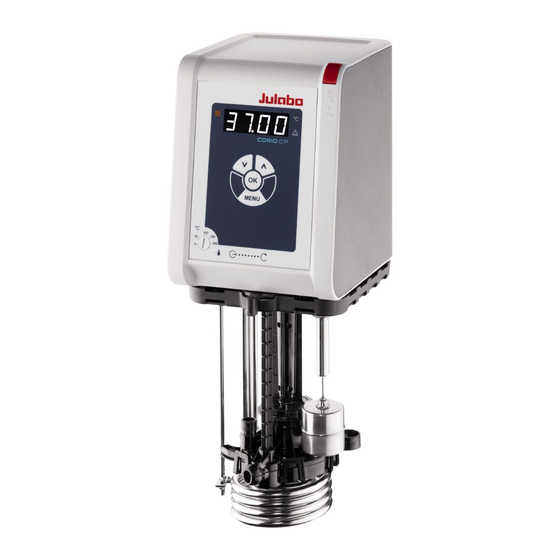
Product description Operating and functional elements The following figure shows the operating and functional elements and their position on the unit. Fig. 1: Control and function elements Mains switch Heating control LED LED display Alarm control LED Cooling control LED Keypad with display Service key (covered) High temperature cut-off setting... -
Page 15: Key Description
Product description 5.3.1 Key description The device is operated using the key panel. This is used to control all menu functions and make entries. Function The [OK] key is used to start a temperature control application or to stop a running temperature control application. - Page 16 Product description RS232 interface factory setting Parity straight Baud rate 4800 baud Handshake Hardware Data bit Stop bit...
-
Page 17: Operating Interface
Product description Operating interface The device is operated using the four navigation keys. The figure shows the menu structure of the user interface. Menu structure... -
Page 18: Alarm Messages
Product description Alarm messages Alarms and warnings are indicated on the display using error codes. Important error code descriptions can be found in the appendix. If you are unable to rectify a fault, contact Technical Service. Alarm: In the event of an alarm, the control LED lights up. The temperature control is stopped. -
Page 19: Main Menu
Product description Main menu The [MENU] key is used to access the main menu. The Main menu is divided into menu options, which respectively contain more submenus or in which settings can be specified. The main menu can be exited by pressing the [OK] key or by pressing the [MENU] key again. -
Page 20: Technical Data
Product description Technical data Performance specifications measured in accordance with DIN12876. Cooling capacities up to 20°C measured with ethanol; over 20°C with thermal oil unless specified otherwise. Performance specifications apply at an ambient temperature of 20°C. Performance values may differ with other bath fluids. Grouping of the device acc. - Page 21 Product description Technical data CORIO CP Working temperature range °C +20 … +200 Temperature stability °C ± 0.03 Temperature resolution °C 0.01 Temperature control PID1 Temperature setting Digital ATC sensor adjustment 3-point adjustment Pump Volume flow rate at 0 bar l/min 8…...
-
Page 22: Material Of Parts That Come Into Contact With The Medium
Product description 5.8.1 Material of parts that come into contact with the medium The table lists parts that could come into contact with the bath fluid as well as the material that the parts are made of. This data can be used to check the compatibility of the parts with the bath fluid used. -
Page 23: Technical Data For Refrigerated Circulators
Product description 5.8.2 Technical data for refrigerated circulators This section lists the technical data of the refrigerated circulator. Technical data CORIO CP-200F Working temperature range °C -20 … +200 Cooling capacity °C 0.20 0.17 0.15 0.10 0.02 Refrigerant R134A Dimensions... - Page 24 Product description Technical data CORIO CP-201F Working temperature range °C -20 … +200 Cooling capacity °C 0.20 0.17 0.15 0.10 0.02 Refrigerant R134A Dimensions Dimensions (W x D x H) 44 x 41 x 44 Usable bath opening 13 x 15 Bath depth Volumes min.
- Page 25 Product description Technical data CORIO CP-300F Working temperature range °C -25 … +200 Cooling capacity °C 0.30 0.30 0.27 0.19 0.08 Refrigerant R134A Dimensions Dimensions (W x D x H) 24 x 42 x 66 Usable bath opening 13 x 15 Bath depth Volumes min.
- Page 26 Product description Technical data CORIO CP-310F Working temperature range °C -30… +200 Cooling capacity °C 0.30 0.27 0.21 0.12 0.02 Refrigerants R449A, R290 Dimensions Dimensions (W x D x H) 23 x 40 x 65 Usable bath opening 13 x 15 Bath depth Volumes min.
- Page 27 Product description Technical data CORIO CP-450F Working temperature range °C -30… +200 Cooling capacity °C 0.44 0.37 0.27 0.16 0.06 Refrigerants R449A, R290 Dimensions Dimensions (W x D x H) 23 x 40 x 65 Usable bath opening 13 x 15 Bath depth Volumes min.
- Page 28 Product description Technical data CORIO CP-600F Working temperature range °C -35… +200 Cooling capacity °C R452A* 0.60 0.54 0.50 0.33 0.19 0.07 R449A 0.60 0.54 0.44 0.27 0.16 0.04 Refrigerants R449A, R452A** Dimensions Dimensions (W x D x H) 33 x 47 x 69...
- Page 29 Product description Technical data CORIO CP-601F Working temperature range °C -35… +200 Cooling capacity °C R452A* 0.60 0.54 0.50 0.33 0.19 0.07 R449A 0.60 0.54 0.44 0.27 0.16 0.04 Refrigerants R449A, R452A** Dimensions Dimensions (W x D x H) 36 x 46 x 74...
- Page 30 Product description Technical data CORIO CP-900F Working temperature range °C -38 … +200 Cooling capacity °C 0.90 0.85 0.80 0.52 0.31 0.11 Refrigerant R449A Dimensions Dimensions (W x D x H) 39 x 62 x 75 Usable bath opening 26 x 35 Bath depth Volumes min.
- Page 31 Product description Technical data CORIO CP-1000F Working temperature range °C -50 … +200 Cooling capacity °C 1.00 0.96 0.73 0.51 0.25 0.11 Refrigerant R449A Dimensions Dimensions (W x D x H) 42 x 49 x 74 Usable bath opening 18 x 13 Bath depth Volumes min.
- Page 32 Product description Technical data CORIO CP-1000FW Working temperature range °C -50… +200 Cooling capacity °C 1.00 0.96 0.73 0.51 0.25 0.11 Refrigerant R449A Dimensions Dimensions (W x D x H) 42 x 49 x 70 Usable bath opening 18 x 13 Bath depth Volumes min.
- Page 33 Product description Technical data CORIO CP-1001F Working temperature range °C -38… +100 Cooling capacity °C 1.00 0.95 0.85 0.60 0.32 0.12 Refrigerant R449A Dimensions Dimensions (W x D x H) 45 x 64 x 95 Usable bath opening 35 x 41 Bath depth Volumes min.
-
Page 34: Bath Fluids
Recommended bath fluids and further information can be found on our website NOTE No liability accepted for usage of bath fluids that are not suitable! Unsuitable bath fluids that are not approved by JULABO can damage the water bath. • Use bath fluids that are recommended by JULABO •... -
Page 35: Hoses
Product description 5.8.4 Hoses Hoses for connection of an external system must suit the working temperature range and the respective temperature control application. Hoses for every area of application can be found on our website. Hoses must meet the following requirements: •... -
Page 36: Transport And Installation
Transport and installation Transport and installation This section describes how to transport the unit safely. Transporting the device A circulator can be transported with the cooling machine when mounted. CAUTION Risk of crushing by falling device! A device that is not secured appropriately can fall down during improper transport and cause crushing injuries. -
Page 37: Install The Device At The Operating Location
Transport and installation Install the device at the operating location This section describes how the device is set up at the installation location. The device has been transported to the operation location. The size and infrastructure of the operation location are suitable for device operation. -
Page 38: Initial Operation
Initial operation Initial operation Connect the device to the power supply 7.1.1 Connect bridge mounted or heating circulator This section describes how the circulator is connected as a bridge mounted circulator or heating circulator. The circulator is mounted as a bridge mounted or heating circulator. ... -
Page 39: Connect Refrigerated Circulator
Initial operation 7.1.2 Connect refrigerated circulator This section describes how the circulator is connected as a refrigerated circulator. The circulator is mounted on a refrigeration unit. The connection cable, mains cable and CAN bus cable are ready for use. 1. -
Page 40: Connecting An External System
Initial operation Connecting an external system The device is designed for tempering external, closed loop systems. An external system is connected to the unit’s pump connections. CAUTION Risk of burns due to damaged temperature control hoses! Hot bath fluid can escape from damaged temperature control hoses and cause serious burns when it comes into contact with skin. -
Page 41: Connect An External System With Screw Connections
Initial operation NOTE Overflowing bath fluid due to externally connected systems! If the externally connected system is higher than the temperature control system, bath fluid can flow back and overflow when switched off. • Position the connected external system on the same level or lower than the temperature control system •... - Page 42 Initial operation 3. Screw the hoses onto the pump connectors by hand. Pay attention to the supply and runback position. 4. Screw on the pump connections carefully with a maximum of 3 Nm torque. 5. Set the flow direction adjustment lever to external circulation. ...
-
Page 43: Connect An External System With Barbed Fittings
Initial operation 7.2.2 Connect an external system with barbed fittings This section describes how to connect an external, closed system to the device using barbed fittings. Open-end wrench, 17 mm Open-end wrench, 19 mm The circulator is equipped with the optional assembly frame or pump set. ... -
Page 44: Set High Temperature Safety Function
Initial operation Set high temperature safety function Before each new temperature application, the temperature must be set for the tank and internal reservoir high temperature cut-off. Set a value that is at least 25 K below the flash point of the bath fluid being used. The surface temperature of the bath fluid must not exceed the flash point at any time. -
Page 45: Fill Device
Initial operation Fill device This section describes how the device should be filled with bath fluid during initial operation. Specifications for filling volume can be found in the technical data. The drain valve is closed. The device is switched off. 1. -
Page 46: Adjusting The Flow Of The Bath Fluid
Initial operation Adjusting the flow of the bath fluid The flow direction of the bath fluid is set using the lever on the front control: • Lever position left (external): The bath fluid is mainly fed into the external application. •... -
Page 47: Set Chiller Mode
Initial operation Set chiller mode For a refrigerated circulator, the chiller mode is preset ex works to automatic operation. Three different chiller modes can be selected in the operating menu: • Auto: The controller calculates the duration of the heating process in the event of a setpoint change of more than +5 K. -
Page 48: Operation
Operation Operation Switch on the unit This section describes how to switch on the device. The device is connected and ready for operation. 1. Switch the device on at the mains switch. All display elements light up briefly, the software boots and starts the device. -
Page 49: Start Temperature Control Application
The temperature control application can be stopped with the [OK] key. Observe the following for heating circulators: For temperature control applications near or below the ambient temperature: Use a cooling coil or JULABO immersion cooler. -
Page 50: Activate Autostart Function
Operation Activate autostart function The autostart function makes it possible to start a temperature control application directly using the mains switch or via an intermediate timer. The device is configured ex works in such a ways that it switches to a safe operating status in the event of power failure. -
Page 51: Reading Out Blackbox Data
Operation The recording of measurement data is started and indicated on the display by a flashing dot. Use the arrow keys to select <OFF> and stop data recording and confirm with [OK]. 8.6.2 Reading out blackbox data The blackbox stores all relevant data from the last 20 minutes. In addition, the black box logs alarms and warnings. -
Page 52: Remote Control Device Using Usb Interface
1. Connect the circulator (USB port type B) to the computer with a standard USB cable. 2. Download the suitable USB driver from the download area of the website www.julabo.com. Depending on the operating system used by the connected computer, it may be necessary to install the USB driver. -
Page 53: Remote Control Device Using Rs232 Interface
Operation The display flashes briefly. 8. Use the arrow keys to select <PAr> (parity) and confirm with [OK]. 9. Use the arrow keys to select <nonE> (no parity), <odd> (odd), or <EvEn> (even) and confirm with [OK]. If parity is <nonE>, the number of data bits is set to 8. ... -
Page 54: Setting The Timer
Operation Setting the timer The timer can be used to program the duration of a temperature control application from 0 to 999 minutes. The setpoint temperature is maintained for the programmed time. After the set duration has elapsed, the device switches to standby mode. -
Page 55: Adjust Internal Temperature Sensor
Operation • 2-point adjustment: When the temperature is controlled between two setpoints. The slope of the temperature curve is adjusted between two points. • 3-point adjustment: When temperature is controlled within a temperature range. This results in an arched temperature curve. 8.10.1 Adjust internal temperature sensor This section describes how to adjust the internal temperature sensor of the device. -
Page 56: Enabling Atc Function
Operation 8.10.2 Enabling ATC function For regular operation, the correction values saved for an adjustment can be enabled in the menu. The device is switched on. Correction values are saved. 1. Press the [MENU] key. 2. Use the arrow keys to select the menu option <Atc> and confirm with [OK]. -
Page 57: Maintenance
1. Check the safety signs on the device for legibility and completeness. 2. Replace defective or missing safety markings. Safety signs can be reordered from JULABO. The safety signs on the device have been checked. Check the functionality of high temperature cut-off This section describes how you can test that the high temperature safety function is operational. -
Page 58: Test The Low Liquid Level Safety Function
See type plate for mains voltage and current value. We recommend only using original JULABO spare parts. Emptying The device must be completely drained if it is to be sent in for technical service or is to be properly disposed of. -
Page 59: Clean Device
Maintenance CAUTION Risk of burns from hot bath fluid! Bath fluid can become very hot during a temperature control process. Contact with hot bath fluid can cause scalding. • Before draining the device, let it cool to room temperature • Avoid direct contact with hot bath fluid •... -
Page 60: Device Storage
The device is protected and can be safely stored there. It can be put into operation again as needed. Technical Service If the unit shows faults you cannot resolve, please contact our Technical Service. JULABO Technical Service Tel.: +1(610) 231-0250 Option 3 Fax: +1(610) 231-260 Email: Service@julabo.us... -
Page 61: Warranty
Warranty The following Warranty Provisions shall apply to products sold in North America by Julabo (“Seller”) to the entity shown as buyer (“Buyer”) on Seller’s invoice. Initial Warranty Upon Seller’s receipt of payment in full for the products and subject to Buyer’s... - Page 62 Maintenance be extended. All repairs or replacements performed by Seller pursuant to these Warranty Provisions shall be performed at one of the Seller’s facility in Allentown, Pennsylvania, U.S.A. or at the facility of an authorized representative of Seller, which location shall be determined by Seller in its sole discretion; provided, however, that Seller may, in its sole discretion perform such repairs or replacements at Buyer’s facility in which case Buyer shall pay Seller’s travel, living and related expenses incurred by Seller in performing the repairs or...
-
Page 63: Disposal
The same exclusions that apply to the regular warranty also apply to OBF classification. For example, JULABO will not be liable for transport damage, damage inflicted by the customer or any other party, or defects arising from improper installation or usage. -
Page 64: Appendix
Appendix 11 Appendix 11.1 Interface commands Interface commands allow the device to be remote controlled. Parameters can be retrieved and the current status can be queried. To do this, the device must be connected to the master computer via a digital interface. Interface commands are entered using a terminal program. -
Page 65: In Commands
Appendix 11.1.1 IN commands IN commands retrieve device parameters. Process values System response in_pv_00 Actual value in_pv_01 Current variable (%) in_pv_03 Current temperature of the temperature safety sensor in_pv_04 Current setting of the high temperature safety function Setpoints and warning System response limits in_sp_00... -
Page 66: Out Commands
Appendix 11.1.2 OUT commands OUT commands set device parameters. Remote control mode must be active. Parameter Parameter Setting settings out_sp_00 xxx.xx Setting for the setpoint temperature out_sp_03 xxx.xx Setting for the high temperature out_sp_04 xxx.xx Setting of the low temperature out_sp_07* Set pump to preset levels 1…5 out_sp_27... -
Page 67: Status Messages
Appendix 11.1.4 Status messages Possible status messages from the device for a status query. Status message Explanation 00 MANUAL STOP Device in standby mode manual operation 01 MANUAL START Device in manual mode 02 REMOTE STOP Device in standby mode, remote control operation 03 REMOTE START Device in remote control mode -08 INVALID... -
Page 68: Alarms And Warnings
Appendix 11.2 Alarms and Warnings If the device is connected to a network and remotely controlled, a status query via interface command will output any pending alarms or warnings as text. Alarm and warning messages are described in the table. If a displayed error code is not described in the table or the error is still pending after switching off and on again, please contact Technical Service. - Page 69 Appendix Error code Description Solution Communication error between • Check CAN bus cable for damage and circulator and connected refrigeration replace if necessary. Switch the unit on unit. again. If the fault has not been remedied, contact Technical Service. • Alternatively: Deactivate the refrigeration unit.
- Page 70 Appendix Error code Description Solution • For water-cooled units: Check cooling water temperature and supply. • If the fault has not been remedied, contact Technical Service. • -431 The maximum permissible current Check mains voltage for nominal consumption at the compressor has voltage.
-
Page 71: Error Messages In Configuration Process
Appendix 11.3 Error messages in configuration process If errors occur during a configuration process or during a firmware update, these are shown on the display as error codes in ticker text. Error code Description Solution CFG error Error during configuration. •...
Need help?
Do you have a question about the CORIO CP and is the answer not in the manual?
Questions and answers