
Subscribe to Our Youtube Channel
Related Manuals for Julabo Corio CP


Summary of Contents for Julabo Corio CP
- Page 1 Heating immersion circulator, heating circulator with open bath, refrigerated circulator Operating manual 1.950.0900.us.V03 12/2021...
- Page 2 Legal JULABO USA, Inc. 884 Marcon Boulevard Allentown, PA 18109 Phone: +1(610) 231-0250 Fax.: +1(610) 231-0260 Info@julabo.us www.julabo.us The content of this operating manual is protected by copyright. Information, including texts, images, and other contents may not be reproduced, distributed, transmitted, stored or otherwise used in any form without prior explicit written consent.
-
Page 3: Table Of Contents
Foreword .................... 6 About this manual ................7 Accessories ..................7 Warnings ..................7 Symbols used ................. 8 Intended use ..................9 Safety ....................10 General Safety Instructions for the operating company....10 General Safety Instructions for the operator ......... 10 General Safety instructions for device operation ...... - Page 4 Connecting an external system ............ 37 7.2.1 Connect an external system with screw connections ....38 7.2.2 Connect an external system with barbed fittings ..... 40 Set high temperature safety function ..........41 Fill device ..................42 Set up power supply for the refrigerated circulator ....... 42 Adjusting the flow of the bath fluid ..........
- Page 5 Device storage ................57 Technical Service ................. 58 Warranty ..................58 Disposal ................... 61 10.1 Device disposal ................61 Appendix ..................62 11.1 Interface commands ..............62 11.1.1 IN commands ................63 11.1.2 OUT commands ..............64 11.1.3 Status commands ..............64 11.1.4 Status messages ..............
-
Page 6: Foreword
Foreword Congratulations! You have made an excellent choice. JULABO would like to thank you for the trust you have placed in our company and products. This operating manual will help you become acquainted with the use of our units. Read the operating manual carefully. Keep the operating manual handy at... -
Page 7: About This Manual
Read the Safety section of this manual before using the equipment for the first time. Accessories JULABO offers a wide range of accessories for the devices. Accessories are not described in this manual. The complete range of accessories for the devices described in this manual can be found on our website www.julabo.com. -
Page 8: Symbols Used
About this manual DANGER This signal word designates a danger with a high level of risk which, if it not prevented, will result in death or serious injuries. NOTE This signal word designates a possibly harmful situation. If it is not avoided, the system or objects in its vicinity may be damaged. -
Page 9: Intended Use
This section defines the purpose of the unit so that the operator can operate the unit safely and avoid misuse. JULABO circulators are laboratory devices that are designed for temperature control applications with liquid media in a bath tank or with a cooling machine. -
Page 10: Safety
Safety Safety General Safety Instructions for the operating company This section outlines the General Safety Instructions that must be observed by the operator to ensure safe operation. • The operator is responsible for the qualifications of its operating personnel. • The operator must ensure that the operating personnel has been instructed in use of the device. -
Page 11: General Safety Instructions For Device Operation
Safety • Do not remove safety symbols • Have all service and repair work carried out by authorized specialists only • Protect device from dirt • Protect device direct UV radiation General Safety instructions for device operation This section lists the General Safety Instructions for device operation. These Safety Instructions must be followed to ensure safe operation. -
Page 12: Safety Symbols
Safety Safety symbols There are safety symbols included with the device, which should be attached to the device before initial operation. Safety Description symbols Warning of a danger zone. Note operating manual Warning about hot surface Warning of cold surface Read operating manual before switching on Safety function Technical protective devices provide for safe operation. - Page 13 Safety Overheating protection The overheating protection prevents overheating of the heater. • The protective mechanism is triggered when the device recognizes a temperature difference of more than 20 K between the working temperature sensor and the safety temperature sensor. Am error message appears on the display.
-
Page 14: Product Description
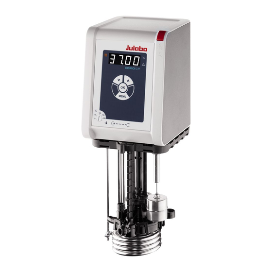
Refrigerated circulator circulator CORIO CP circulator Circulator with closed Circulator with cooling stainless steel bath tank. machine. Example: CORIO CP-BC4 for Example: CORIO CP-300F for temperature control standard temperature application in the bath or an applications external application Function description This section describes the function of the device. -
Page 15: Operating And Functional Elements
Product description Operating and functional elements The following figure shows the operating and functional elements and their position on the unit. Fig. 1: Control and function elements Mains switch Heating control LED LED display Alarm control LED Cooling control LED Membrane keypad with key panel Service key (covered) High temperature cut-off setting... -
Page 16: Key Description
Product description 5.3.1 Key description The device is operated using the key panel. This is used to control all menu functions and make entries. Function The [OK] key is used to start a temperature control application or to stop a running temperature control application. -
Page 17: Operating Interface
Product description Operating interface The device is operated using the four navigation keys. The figure shows the menu structure of the user interface. Menu structure... -
Page 18: Main Menu
Product description Main menu The [MENU] key is used to access the main menu. The Main menu is divided into menu options, which respectively contain more submenus or in which settings can be specified. The main menu can be exited by pressing the [OK] key or by pressing the [MENU] key again. -
Page 19: Interfaces
Product description Interfaces 5.7.1 RS232 interface The RS232 interface is a 9-pin D-Sub socket for connecting the device to a PC. RS232 plug RS232 interface pin assignment Pin 2 RxD receive data Pin 7 RTS request to send Pin 3 TxD transmit data Pin 8 CTS clear to send... -
Page 20: Technical Data
Product description Technical data Performance specifications measured in accordance with DIN12876. Cooling capacities up to 20°C measured with ethanol; over 20°C with thermal oil unless specified otherwise. Performance specifications apply at an ambient temperature of 20°C. Performance values may differ with other bath fluids. Grouping of the device acc. - Page 21 Product description Technical data CORIO CP Working temperature range °C +20 … +200 Temperature stability °C ± 0.03 Temperature resolution °C 0.01 Temperature control PID1 Temperature setting Digital ATC sensor adjustment 3-point adjustment Pump Volume flow rate at 0 bar l/min 8 …...
-
Page 22: Material Of Parts That Come Into Contact With The Medium
Product description 5.8.1 Material of parts that come into contact with the medium The table lists parts that could come into contact with the bath fluid as well as the material that the parts are made of. This data can be used to check the compatibility of the parts with the bath fluid used. -
Page 23: Technical Data For Refrigerated Circulators
Product description 5.8.2 Technical data for refrigerated circulators This section lists the technical data of the refrigerated circulator. Technical data CORIO CP-200F Working temperature range °C -20 … +200 Cooling capacity °C 0.20 0.17 0.15 0.10 0.02 Refrigerant R134A Dimensions... - Page 24 Product description Technical data CORIO CP-201F Working temperature range °C -20 … +200 Cooling capacity °C 0.20 0.17 0.15 0.10 0.02 Refrigerant R134A Dimensions Dimensions (W x D x H) 44 x 41 x 44 Usable bath opening 13 x 15 Bath depth Volumes min.
- Page 25 Product description Technical data CORIO CP-300F Working temperature range °C -25 … +200 Cooling capacity °C 0.30 0.30 0.27 0.19 0.08 Refrigerant R134A Dimensions Dimensions (W x D x H) 24 x 42 x 66 Usable bath opening 13 x 15 Bath depth Volumes min.
- Page 26 Product description Technical data CORIO CP-600F Working temperature range °C -35 … +200 Cooling capacity °C R452A* 0.60 0.54 0.50 0.33 0.19 0.07 R449A 0.60 0.54 0.44 0.27 0.16 0.04 Refrigerant R449A, R452A* Dimensions Dimensions (W x D x H)
- Page 27 Product description Technical data CORIO CP-601F Working temperature range °C -35 … +200 Cooling capacity °C R452A* 0.60 0.54 0.50 0.33 0.19 0.07 R449A 0.60 0.54 0.44 0.27 0.16 0.04 Refrigerant R449A, R452A* Dimensions Dimensions (W x D x H)
- Page 28 Product description Technical data CORIO CP-900F Working temperature range °C -38 … +200 Cooling capacity °C 0.90 0.85 0.80 0.52 0.31 0.11 Refrigerant R449A Dimensions Dimensions (W x D x H) 39 x 62 x 75 Usable bath opening 26 x 35 Bath depth Volumes min.
- Page 29 Product description Technical data CORIO CP-1000F Working temperature range °C -50 … +200 Cooling capacity °C 1.00 0.96 0.73 0.51 0.25 0.11 Refrigerant R449A Dimensions Dimensions (W x D x H) 42 x 49 x 74 Usable bath opening 18 x 13 Bath depth Volumes min.
- Page 30 Product description Technical data CORIO CP-1001F Working temperature range °C -38 … +100 Cooling capacity °C 1.00 0.95 0.85 0.60 0.32 0.12 Refrigerant R449A Dimensions Dimensions (W x D x H) 45 x 64 x 95 Usable bath opening 35 x 41 Bath depth Volumes min.
-
Page 31: Bath Fluids
Recommended bath fluids and further information can be found on our website NOTE No liability accepted for usage of bath fluids that are not suitable! Unsuitable bath fluids that are not approved by JULABO can damage the water bath. • Use bath fluids that are recommended by JULABO •... -
Page 32: Hoses
Product description 5.8.4 Hoses Hoses for connection of an external system must suit the working temperature range and the respective temperature control application. Hoses for every area of application can be found on our website. Hoses must meet the following requirements: •... -
Page 33: Transport And Installation
Transport and installation Transport and installation This section describes how to transport the unit safely. Transporting the device A circulator can be transported with the cooling machine when mounted. CAUTION Risk of crushing by falling device! A device that is not secured appropriately can fall down during improper transport and cause crushing injuries. -
Page 34: Install The Device At The Operating Location
Transport and installation Install the device at the operating location This section describes how the device is set up at the installation location. The device has been transported to the operation location. The size and infrastructure of the operation location are suitable for device operation. -
Page 35: Initial Operation
Initial operation Initial operation Connect the device to the power supply 7.1.1 Connect bridge mounted or heating circulator This section describes how the circulator is connected as a bridge mounted circulator or heating circulator. The circulator is mounted as a bridge mounted or heating circulator. ... -
Page 36: Connect Refrigerated Circulator
Initial operation 7.1.2 Connect refrigerated circulator This section describes how the circulator is connected as a refrigerated circulator. The circulator is mounted on a cooling machine. The network extension cable, power cable and CAN bus cable are ready for use. -
Page 37: Connecting An External System
Initial operation Connecting an external system The device is designed for tempering external, closed loop systems. An external system is connected to the unit’s pump connections. CAUTION Risk of burns due to damaged temperature control hoses! Hot bath fluid can escape from damaged temperature control hoses and cause serious burns when it comes into contact with skin. -
Page 38: Connect An External System With Screw Connections
Initial operation NOTE Overflowing bath fluid due to externally connected systems! If the externally connected system is higher than the temperature control system, bath fluid can flow back and overflow when switched off. • Position the connected external system on the same level or lower than the temperature control system •... - Page 39 Initial operation 1. Disassemble the union nuts on the pump connectors. 2. Remove the sealing plugs. 3. Screw the hoses onto the pump connectors by hand. Pay attention to the supply and runback position. 4. Screw on the pump connections carefully with a maximum of 3 Nm torque. 5.
-
Page 40: Connect An External System With Barbed Fittings
Initial operation 7.2.2 Connect an external system with barbed fittings This section describes how to connect an external, closed system to the device using barbed fittings. Open-end wrench, 17 mm Open-end wrench, 19 mm The circulator is equipped with the optional assembly frame or pump set. ... -
Page 41: Set High Temperature Safety Function
Initial operation Set high temperature safety function Before each new temperature application, the temperature must be set for the tank and internal reservoir high temperature cut-off. Set a value that is at least 25 K below the flash point of the bath fluid being used. The surface temperature of the bath fluid must not exceed the flash point at any time. -
Page 42: Fill Device
Initial operation Fill device This section describes how the device should be filled with bath fluid during initial operation. Specifications for filling volume can be found in the technical data. The drain valve is closed. The device is switched off. 1. -
Page 43: Adjusting The Flow Of The Bath Fluid
Initial operation 5. Select <On> or <OFF> and confirm with [OK]. <On> when device combination is connected to same power supply. The heating power limit is activated. Depending on the total current consumption, it limits the heating power of the circulator and prevents overloading of the power supply. -
Page 44: Set Chiller Mode
Initial operation Set chiller mode For a refrigerated circulator, the chiller mode is preset ex works to automatic operation. Three different chiller modes can be selected in the operating menu: • Auto: The controller calculates the duration of the heating process in the event of a setpoint change of more than +5°K. - Page 45 Initial operation 5. Use the arrow keys to set the decimal point and confirm with [OK]. The set value is confirmed by flashing briefly. The display switches to <tHi>. 6. Use the arrow keys to switch to the low temperature limit <tLo> then repeat steps 3 and 4 for the lower temperature limit.
-
Page 46: Operation
Operation Operation Switch on the unit This section describes how to switch on the device. The device is connected and ready for operation. 1. Switch the device on at the mains switch. All display elements light up briefly, the software boots and starts the device. -
Page 47: Activate Autostart Function
Operation 3. Use the arrow keys to set the value after the decimal point and confirm with [OK]. The set value is applied. The new setpoint temperature flashes briefly. The setpoint temperature is set and active. Setpoint temperature configuration can be interrupted using the [MENU] key. -
Page 48: Record Data
Operation Record data 8.5.1 Record measurement data Measurement data for an ongoing temperature control application can also be recorded onto a USB stick at the same time. The target value temperature, actual value temperature, and the percentage output are documented every second in the record. -
Page 49: Adjust Pump
1. Connect the circulator (USB port type B) to the computer with a standard USB cable. 2. Download the suitable USB driver from the download area of the website www.julabo.com. Depending on the operating system used by the connected computer, it may be necessary to install the USB driver. -
Page 50: Set Interface Parameters
Operation 9. Start the terminal program on the computer. 10. Use the terminal program to select the COM port of the circulator and establish a connection. Remote control via the USB interface is activated. You can now remote control the circulators using interface commands from the computer. 8.7.2 Set interface parameters The interface parameters cannot be changed during remote control mode. -
Page 51: Request Device Status
Operation 5. Use the arrow keys to select the menu option <rEM> and confirm with [OK]. 6. Use the arrow keys to select <232> and confirm with [OK]. 7. Start the terminal program on the computer. 8. Enter the interface parameters into the terminal program. ... -
Page 52: Adjusting The Temperature Sensor (Atc)
Operation 4. Confirm with [OK]. The display flashes briefly. The timer is programmed and active. The decimal point flashes on the display until the setpoint temperature is reached. The timer starts once the setpoint temperature has been reached. The actual temperature and remaining operating time are now displayed in turns. -
Page 53: Adjust Internal Temperature Sensor
Operation 8.9.1 Adjust internal temperature sensor This section describes how to adjust the internal temperature sensor of the device. The bath tank is filled. The device is switched on. The ATC function is disabled. 1. Hang the calibrated thermometer in the bath tank and place the bath lid on top. -
Page 54: Device Reset
Operation 4. Use the arrow keys to select <On> and confirm with [OK]. The display flashes briefly. The ATC function is activated. The stored correction values are offset against the temperature measured internally. 8.10 Device Reset The function resets the device to the factory settings. ... -
Page 55: Maintenance
1. Check the safety signs on the device for legibility and completeness. 2. Replace defective or missing safety markings. Safety signs can be reordered from JULABO. The safety signs on the device have been checked. Check the functionality of high temperature cut-off This section describes how you can test that the high temperature safety function is operational. -
Page 56: Replace Detachable Power Cord
See type plate for mains voltage and current value. We recommend only using original JULABO spare parts. Emptying The device must be completely drained if it is to be sent in for technical service or is to be properly disposed of. -
Page 57: Clean Device
Maintenance Clean device The circulator and bath tank, and also a cooling machine if connected, should be cleaned from time to time. In addition to this, the device must be appropriately decontaminated if hazardous substances have been spilled on or into the device. ... -
Page 58: Technical Service
Warranty The following Warranty Provisions shall apply to products sold in North America by Julabo (“Seller”) to the entity shown as buyer (“Buyer”) on Seller’s invoice. Initial Warranty Upon Seller’s receipt of payment in full for the products and subject to Buyer’s... - Page 59 Maintenance Exclusions The Initial Warranty does not include damage to the product resulting from accident, misuse, improper installation or operation, unauthorized or improper repair, replacement or alteration (including but not limited to repairs, replacements, or alterations made or performed by persons other than Seller’s employees or authorized representatives), failure to provide (or use of improper) maintenance, unreasonable or unintended use or abuse of the product, or failure to follow written installation or operating instructions.
- Page 60 The same exclusions that apply to the regular warranty also apply to OBF classification. For example, JULABO will not be liable for transport damage, damage inflicted by the customer or any other party, or defects arising from improper installation or...
-
Page 61: Disposal
Disposal 10 Disposal 10.1 Device disposal When disposing of the device, the applicable country-specific guidelines must be observed. The circulator combination is switched off and disconnected from the mains voltage. 1. Empty the bath tank or cooling machine completely. 2. -
Page 62: Appendix
Appendix 11 Appendix 11.1 Interface commands Interface commands allow the device to be remote controlled. Parameters can be retrieved and the current status can be queried. To do this, the device must be connected to the master computer via a digital interface. Interface commands are entered using a terminal program. -
Page 63: In Commands
Appendix 11.1.1 IN commands IN commands retrieve device parameters. Process values System response in_pv_00 Actual value in_pv_01 Current variable (%) in_pv_03 Current temperature of the temperature safety sensor in_pv_04 Current setting of the high temperature safety function Setpoints and warning System response limits in_sp_00... -
Page 64: Out Commands
Appendix 11.1.2 OUT commands OUT commands set device parameters. Remote control mode must be active. Parameter Parameter Setting settings out_sp_00 xxx.xx Setting for the setpoint for temperature control out_sp_03 xxx.xx Setting for the high temperature out_sp_04 xxx.xx Setting of the low temperature out_sp_07* Set pump to preset levels 1…5 out_sp_27... -
Page 65: Status Messages
Appendix 11.1.4 Status messages Possible status messages from the device for a status query. Status message Explanation 00 MANUAL STOP Device in standby mode manual operation 01 MANUAL START Device in manual mode 02 REMOTE STOP Device in standby mode, remote control operation 03 REMOTE START Device in remote control mode -08 INVALID... -
Page 66: Alarms And Warnings
Appendix 11.2 Alarms and Warnings If the device is connected to a network and remotely controlled, a status query via interface command will output any pending alarms or warnings as text. Alarm and warning messages are described in the table. If a displayed error code is not described in the table or the error is still pending after switching off and on again, please contact Technical Service. - Page 67 Appendix Error code Description Solution Internal write/read error • Switch off the device at the mains switch, wait 4 seconds and then switch the device on again. Communication error between • Check CAN bus cable for damage and circulator and connected refrigeration replace if necessary.
- Page 68 Appendix Error code Description Solution • Check condenser for soiling and clean as necessary. • Switch off the device at the mains switch, wait 4 seconds and then switch the device on again. • For water-cooled units: Check cooling water temperature and supply. •...
- Page 69 Appendix • -1431 Compressor defective or no voltage Check the mains voltage and align it on compressor. with the nominal voltage of the device. • Check the mains cable of the refrigeration unit for damage and replace if necessary. • Check ambient temperature and reduce if necessary.
-
Page 70: Error Messages In Configuration Process
Appendix 11.3 Error messages in configuration process If errors occur during a configuration process or during a firmware update, these are shown on the display as error codes in ticker text. Error code Description Solution • CFG error Error during configuration. Repeat the process.
Need help?
Do you have a question about the Corio CP and is the answer not in the manual?
Questions and answers