Table of Contents
Advertisement
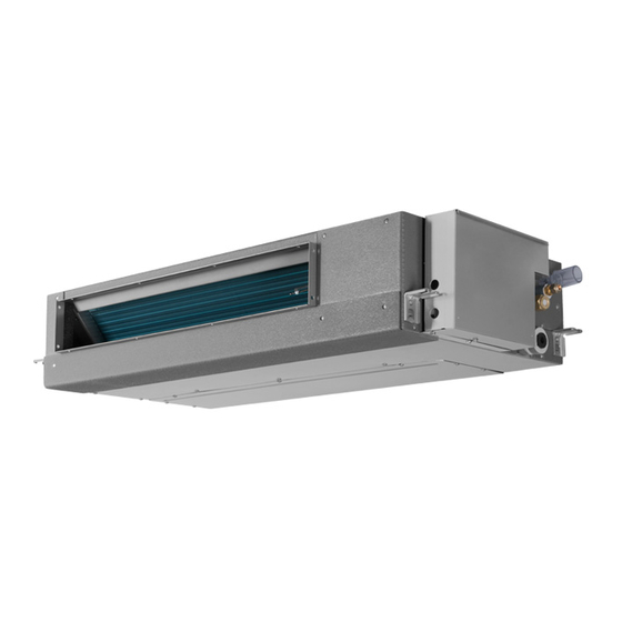
RPIZ-0.8HNDTS1Q
RPIZ-1.0HNDTS1Q
Low-Height
Ceiling Ducted
RPIZ-1.3HNDTS1Q
Type
RPIZ-1.5HNDTS1Q
RPIZ-1.8HNDTS1Q
RPIZ-2.0HNDTS1Q
This manual is exclusively prepared for
R410A indoor unit. Please read this manual
in conjunction with corresponding manual for
outdoor unit.
RPIZ-2.3HNDTS1Q
RPIZ-2.5HNDTS1Q
P01976Q
ORIGINAL INSTRUCTIONS
Advertisement
Table of Contents

Related Manuals for Hitachi RPIZ-0.8HNDTS1Q


Summary of Contents for Hitachi RPIZ-0.8HNDTS1Q
- Page 1 RPIZ-0.8HNDTS1Q RPIZ-2.3HNDTS1Q RPIZ-1.0HNDTS1Q RPIZ-2.5HNDTS1Q Low-Height Ceiling Ducted RPIZ-1.3HNDTS1Q Type RPIZ-1.5HNDTS1Q RPIZ-1.8HNDTS1Q RPIZ-2.0HNDTS1Q This manual is exclusively prepared for R410A indoor unit. Please read this manual in conjunction with corresponding manual for outdoor unit. P01976Q ORIGINAL INSTRUCTIONS...
- Page 3 This declaration becomes invalid, if technical or operational modifications are introduced without the manufacturer's consent. Johnson Controls Hitachi Air Conditioning Europe SAS is authorized to compile technical file or relevant technical documentation. Address : Rue de Lombardie, Parc Aktiland II – 69800 Saint Priest, France...
- Page 5 This manual describes and introduces this heat pump air conditioner in a unified manner, so it's applicable for your and other air conditioners. ● Hitachi pursues a policy of continuous improvement in design and performance of products. The right is therefore reserved to change specifications without notice. ●...
- Page 6 DANGER ● Please don't perform installation works such as refrigerant piping connection, drain pipe connection, and wiring connection. Violations may result in system leakage, electrical failure or fire. In the case of fire, please turn off the power immediately; please don't touch electrical parts with the hands, or electric shock may arise. ●...
-
Page 7: Checking Product Received
● This appliance can be used by children aged from 8 years and above and persons with reduced physical, sensory or mental capabilities or lack of experience and knowledge if they have been given supervision or instruction concerning use of the appliance in a safe way and understand the hazards involved. Children shall not play with the appliance. - Page 9 Unit Description Part Name 3.1 Indoor Unit 3.2 Remote Control Before Operation Automatic Control Section2 Installation & Maintenance Manual...
- Page 10 Protection and Control Devices Field Operation 10.3 Setting of External Static Pressure...
-
Page 11: Before Operation
3. Part Name 3.1 Indoor Unit Refer to Fig. 3.1 "Low-height ceiling Ducted indoor unit" Do not have the indoor unit or outdoor unit exposed to water. All these parts are designed 3.2 Remote Control with electronic components that may cause Refer to the remote control instruction manual for operation short circuit when exposed to water. - Page 12 Models: 0.8~1.3 Model: 1.5 Models: 1.8~2.5 Fig. 3.1 Low-height ceiling Ducted Indoor Unit...
-
Page 13: Automatic Defrosting
5. Auto Control Automatic Defrosting Press "Run/Stop" key to stop heating. The outdoor This system is designed with the following features. unit can automatically detect frost and automatically perform defrosting for up to 10 minutes. NOTE Overload Protection Please keep the main power supply ON unless the system is left unused for long. - Page 15 Note: When in immediate contact with refrigerant, please use the installation tools and instruments dedicated to the new refrigerant. DANGER Since the pressure of new refrigerant R410A is 1.4 times that of traditional refrigerant, its performance is susceptible to impurities like moisture, scale and grease, etc. It's essential to remove the moisture, dust, other refrigerants or refrigerant oils from the refrigeration system.
- Page 16 Install the indoor unit as per national standard. Please contact the dealer if the accessories are not delivered with machine. Magnet Ring...
- Page 17 Models: 0.8~2.5 Electric Box Back Service Access (≥450) Install suspension bolts as shown in Fig. 4.2. 1. Where the ceiling is not removable, please arrange a necessary service access under the For Concrete Slab For Steel Beam indoor unit. 2. The service Insert 150 to 160mm (100 to150kg)
-
Page 18: Installation Of Indoor Unit
4.3.3 Installation of Indoor Unit 4.3.2 Suspension Bolt and Pipe Connection Points Indoor unit is installed as shown in Fig. 4.4. Installation of Field-Supplied Parts (1) Indicate the location of suspension bolt, and the connection points of refrigerant pipe and drain Suspension Bolt 4-M10 or W3/8 pipe. -
Page 19: Air Duct Connection
4.3.5 Air Duct Connection (2) Installation of Indoor Unit Air duct is connected to indoor unit via canvas hose Place the left bracket on the nut and washer of to effectively isolate noise and vibration. Indoor unit suspension bolt as shown in the figure below. is designed with flange with hole connectible to air Make sure the left bracket is properly placed duct. -
Page 20: Piping Connection
Pipe Diameter (a) Flaring Diameter As shown in Fig. 5.4, two spanners shall be used for tightening the nut. 12.7mm Fig. 5.4 Nut Tightening Torque (3) Select copper pipes based on Fig. 5.2. Insulate the refrigeration piping with field-supplied 5.2 Piping Connection insulating pipe as shown in Fig. -
Page 21: Drain Pipe
Where the relative humidity of air inlet or Excessive and inadequate refrigerant is a ambient air exceeds 80%, an auxiliary drain pan leading cause of system anomaly. Please shall be fabricated at installation site and placed inject the right amount of refrigerant. under the indoor unit, as shown in Fig. - Page 22 ● Turn OFF the main power switch to the indoor unit and the outdoor unit and wait for at least 10 minutes before electrical wiring work or a periodical check is performed. ● Check to ensure that the indoor fan and the outdoor fan have stopped before electrical wiring work or a periodical check is performed.
- Page 23 Terminal Block (TB) Entwine the magnetic ring 3 turns at wires L and N of power cord The View of D Direction Cord Clamps Power Wire Communication Wire Remote Controller Wire Wired Remote Enlarged View of P Part Control Wire Terminal Block (TB) Wiring Communication...
-
Page 24: Field Operation
10. Field Operation 10.1 Field Minimum Wire Size for Power Source Line Electrical Parameters and Wire Size of Indoor Unit Rated Power Cord Signal Wire Indoor Unit Capacity (HP) Power Supply Specifications Specifications Current 0.50A 1.0~1.3 0.50A 220-240V 50/60Hz 0.50A 1.8~2.0 0.90A 2.3~2.5... - Page 25 (1) DIP switch must be set with power sources (c) Model code setting (DSW4) of the indoor and outdoor units in OFF state. No setup is required. The code is set before delivery. Otherwise, the settings are invalid. (2) DIP switch positions are shown in the figure below.
-
Page 26: Setting Of External Static Pressure
10.3 Setting of External Static Pressure The static pressure can be changed by setting the external static pressure ("C5") on the wired remote control. Please refer to the installation and maintenance manual for wired remote control. External Pressure Settings of Wired Indoor Unit Remote Control Capacity (HP) - Page 28 1154120 Qingdao Hisense Hitachi Air-conditioning Systems Co., Ltd. Add.: No. 218, Qianwangang Road, Economic and Technological Development Zone, Qingdao, China The Company is committed to continuous product improvement. We reserve the right, therefore, to alter the product information at any time and without prior announcement.
Need help?
Do you have a question about the RPIZ-0.8HNDTS1Q and is the answer not in the manual?
Questions and answers