Inverter-driven multi-split system heat pump air conditioners (22 pages)
Summary of Contents for Hitachi RPI-2.0FSR
Page 1
INVERTER-DRIVEN MULTI-SPLIT SYSTEM AIR-COOLED HEAT PUMP AIR CONDITIONERS
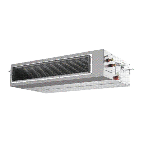
 Ducted Type INDOOR UNITS MODELS HIGH STATIC PRESSURE TYPE RPI-2.0FSR, RPI-2.5FSR, RPI-3.0FSR, RPI-4.0FSR, RPI-5.0FSR, RPI-6.0FSR MEDIUM STATIC PRESSURE TYPE RPIM-0.8FSR, RPIM-1.0FSR, RPIM-1.5FSR, RPIM-2.0FSR, RPIM-2.5FSR, RPIM-3.0FSR, RPIM-4.0FSR, RPIM-5.0FSR, RPIM-6.0FSR EN OPERATION MANUAL Original Instructions...
Important Notice ● HITACHI pursues a policy of continuing improvement in design and performance in its products. As such, HITACHI reserves the right to make changes at any time without prior notice. ● HITACHI cannot anticipate every possible circumstance that might involve a potential hazard.
TABLE OF CONTENTS 1. Introduction ..............................1 2. Safety Instructions ............................1 3. Before Operation .............................9 3.1 Working Range ............................9 3.2 Efficient Use of Indoor Unit ........................9 3.3 Efficient Use of Cooling and Heating ......................9 4. Names of Parts .............................10 4.1 Ducted Type ............................10 4.2 Wired Controller (PC-ARF1) ......................... 11 5. Operation Method ............................12 5.1 Basic Operation ............................12 5.2 Cooling / Heating / Fan Operation ......................13 5.3 Temperature Setting ..........................14...
Refer back to these safety instructions as needed. ● This system should be installed by personnel certified by HITACHI. Personnel must be qualified according to local, state and national building and safety codes and regulations. Incorrect installation could cause leaks, electric shock, fire or explosion. In areas where "Seismic Performance" requirements are specified, the appropriate measures should be taken during installation to guard against possible damage or injury that might occur in an earthquake if the unit is not installed correctly, injuries may occur due to a falling unit.
Page 6
This unit is the pressurized system. Never loosen threaded joints while the system is under pressure and never open pressurized system parts. ● HITACHI will not assume any liability for injuries or damage caused by not following steps outlined or described in this manual. Unauthorized modifications to HITACHI products are prohibited as they… ◦...
Installation Precautions To reduce the risk of serious injury or death, the following installation precautions must be followed. ● When installing the unit into… ◦ A wall: Make sure the wall is strong enough to hold the unit’s weight. It may be necessary to construct a strong wood or metal frame to provide added support.
When shielded cable is applied, proper bonding and termination of the cable shield is required as per HITACHI guidelines. Plenum and riser ratings for communication cables must be considered per application and local code requirements.
Page 9
● Turn OFF and disconnect the unit from the power supply when handling the service connector. Do not open the service cover or access panel to the indoor or outdoor units without turning OFF the main power supply. ● After stopping operation, be sure to wait at least five minutes before turning off the main power switch. Otherwise, water leakage or electrical breakdown may result. Disconnect the power supply completely before attempting any maintenance for electrical parts. Check to ensure that no residual voltage is present after disconnecting the power supply. ● Do not clean with, or pour water into, the controller as it could cause electric shock and/or damage the unit.
● Proper handling of this unit requires two-people. Safe handling and installing the indoor unit requires the strength of two people. Mounting the unit alone may cause injury due to fall of the unit. Although the unit may be girded with steel banding, do not use it for transportation. Avoid contact with finned surfaces of the heat exchanger as sharp edges can cause severe injury to hands and fingers. Use appropriate work gloves for the job. NOTICE ● Check to ensure that the condensate hose discharges moisture properly. If connected incorrectly, it can result in leakage and damage to furniture. ● Make sure to use the factory-supplied condensate hose and hose clamp. Other makes can cause moisture leakage.
Page 11
Operation WARNING ● Do not insert fingers or objects into an air inlet/outlet. Injury can result from rotating fan blades or energized electrical components. ● Do not touch the wired controller with wet hands. It can result in a malfunction of the wired controller or an electrical shock. ● Hair spray, insecticides, lacquers, and other pressurized substances should not be used within 3.3ft (1m) of any air conditioning unit. It can react with energized electrical components and cause fire. ● Do not install the indoor unit anywhere discharge airflow can pass directly toward nearby heating appliances (space heaters). It may interfere with the combustion process in these units. ● When the indoor unit is operated in an area with heat sources, ventilate a room sufficiently. Any leaked refrigerant gases that happen to come into contact with any heat source can become toxic on contact which can cause asphyxiation in the immediate area.
Page 12
Other WARNING ● Turn OFF all power at the main power source before performing maintenance work. Failure to do so can result in damage to internal components with severe or fatal electrical shock. ● Insulate all electrical components and connections from exposure to moisture. Failure to do so can result in an electrical short circuit and fire. ● Do not tamper with or attempt to "repair" electrical wiring or connections. Call your installer or electrical contractor. Serious or fatal injury can occur. ● Perform all maintenance work on a firm and stable foundation to minimize the risk of injury. ● Do not attempt to "clean" indoor unit components with liquid or powdered cleaning agents during maintenance. Electric shock, sparks, flame, and serious or fatal injury can occur. ● Inside piping is charged with refrigerant and highly pressurized. ● Do not spray deodorant inside the indoor unit. The copper pipe will corrode and cause gas leakage. ● Hold the air filter and the air inlet grille firmly when attaching or removing it. Carelessness can result in accident or injury. ● Do not operate the unit without the air filter set in place. If the air filter is not installed, dust may accumulate and breakdown may result.
Before Operation NOTICE Power is turned on. Apply power to the outdoor unit(s) at least 12 hours prior to operation of the system for preheating of the compressor oil. Make sure that the outdoor unit is not covered with snow or ice. If it is, remove it by using hot water that is approximately 50 If the water temperature is higher than 50 C, it will cause damage to plastic parts.
Names of Parts Ducted Type Air Filter The mounting position may Air Inlet Duct Canvas Duct be different depend on the (Field-Supply) (Field-Supply) (Field-Supply) installation condition Air Outlet Duct (Field-Supply) Air Outlet Grille (Field-Supply) Air Inlet Grille Canvas Duct (Field-Supply) (Field-Supply) Indoor Unit Location of Indoor Wired Controller Unit Model Indication (Optional)
4.2 Wired Controller (PC-ARF1) The example below references the control panel and all adjustable settings. The wired controller display may be Display Part different during actual operation. Fan Speed Indicator Schedule Timer Indicator It is indicated when the schedule timer function is set. (*) Operation Mode Indicator Operation Lock Indicator The indications of...
Operation Method Basic Operation By pressing “ ”or “ ”, the icon “ ” will move between “MODE”, “SPEED”, “LOUV.” and “TEMP”. Menu Item Back/Help Selection With (“MODE”, “SPEED”, “LOUV.” or “TEMP”) selected, press “ ” or “ ”. Menu The setting will be changed. Change of Back/Help Settings ● For the ducted unit, “LOUV.” is not displayed on Liquid Crystal Display (LCD).
5.2 Cooling / Heating / Fan Operation Heating Operation is for VRF system only and is not available for other systems. <Function> * Cooling Operation: To decrease the room temperature. * Heating Operation: To increase the room temperature. * Dry Operation: To decrease the humidity in the room. * Cooling/Heating Automatic Operation (AUTO): To cooling and heating automatic changeover. * Fan Operation: To circulate the air in the room. ● Dry operation may not be performed properly if there are other heat sources which exceed the capacity of the unit.
Temperature Setting Press “ ” or “ ” and select “TEMP”. Menu Back/Help By pressing “ ”, the temperature is increased by 0.5°C. (Max. 30°C) Menu By pressing “ ”, the temperature is decreased by 0.5°C. Back/Help COOL, DRY, FAN operation: Min. 19°C HEAT operation: Min. 17°C ●...
5.4 Fan Speed Press “ ” or “ ” and select “SPEED”. Menu Back/Help By pressing “ ” or “ ”, the fan speed will be changed as follows. Menu Back/Help HIGH 2 HIGH AUTO ● During the dry operation, the fan speed is automatically changed to “LOW” and cannot be changed to any other fan speed.
Motion Sensor This setting is available only for the motion sensor kit. <Function> * The motion sensor detects a human activity by the change of the infrared light. This function saves the air conditioning capacity (adjusting the set temperature and the air flow volume) automatically depending on a situation. * The operation after the motion sensor detects as absence can be selected from “Running”, “Stand-by” or “Stop”...
5.6.1 Details for Motion Sensor Control The motion sensor control adjusts automatically the following items depending on a situation. ● Setting Temperature: The temperature is adjusted 1°C or 2°C for saving capacity. ● Air Flow Volume: The air flow volume is adjusted to lower one volume or to “Slo” (except during the dry operation). 5.6.2 Descriptions for Setting Items ● Motion Sensor Setting * ON: The operating control function by the motion sensor is activated.
5.6.3 Setting of Motion Sensor Press “Menu”. Menu 15:10(Fri) Select “Motion Sensor Setting” from the Adjusting Date/Time Daylight Saving Time menu by pressing “ ” or “ ” and press Menu 15:10(Fri) Screen Display Setting Function 19 Individual Louver Setting “OK”.
Page 23
Press “ ” or “ ” and select “Check Menu Motion Sensor Setting interval”. Sensor ALL MODES Back/Help If absent Check interval 30min Sel. Adj. Entr Rtrn Back The display is switched “30min”, “60min”, Menu Motion Sensor Setting “90min”, “120min” and “180min” in order Sensor ALL MODES by pressing “...
Cold Draft Control during Cooling Operation (1) Function This function controls the overcooling airflow to prevent of cold draft. (2) Setting Items * OFF : This function is not available. * LOW : The over-cooling airflow temperature is controlled low degree. * MID : The over-cooling airflow temperature is controlled medium degree. * HIGH : The over-cooling airflow temperature is controlled high degree. (The default setting is “OFF”) (3) Supplement of Function • The discharge air temperature is elevated higher in “HIGH” > “MID” > “LOW” order. • The recommended discharge air temperature setting is “LOW”. (When feeling cold at "LOW", change the setting to “MID” or “HIGH”.) * This function also reduces the formation of dew condensation on the decorative panel when the discharge air temperature is lower than the inlet air temperature in a very humid room.
A setback operation requires extra settings. Refer to the “Installation & Maintenance Manual” for the wired controller and the “Service Manual” for details. Automatic Heating/Cooling Operation In case dual setpoint is selected in automatic heating/cooling operation, during auto mode both cooling setpoint and heating setpoint can be selected.
Automatic Control This air conditioner automatically starts the following operations according to the indoor conditions. The system is equipped with the following functions. ▪ Enforced Stoppage: The compressor remains off for at least three minutes once it has stopped. If the system is started within approximately three minutes after it has stopped, the RUN indicator is activated. However, the cooling operation or the heating operation remains off and does not start until after three minutes has elapsed. Three-Minute Guard ▪ Enforced Operation: If all indoor units of the system are Thermo-OFF within approximately...
Maintenance WARNING ● Turn OFF the power source before the maintenance work. If the power source is not turned OFF, the result may be an electric shock or fire. ● Perform the maintenance work with a stable foothold or foundation. This may prevent falling or injury. ● When cleaning, do not allow water inside the air conditioner. Water on electrical equipment may cause electric shock. ● Do not wash the interior of the indoor unit yourself. Use of commercially available cleaning agents may cause cracking of resin parts, deterioration of internal parts, and clogging of drainage channels, causing water leakage and electric shock. ● Do not spray deodorant inside the indoor unit. The copper pipe will corrode and cause gas leakage. ● Hold the air filter and the air inlet grille securely by hand when attaching or removing it. If not, it may cause the product to fall, resulting in an injury. 7.1 Cleaning Air Filter Clean the air filter when the filter sign is turned ON.
(3) Reset the filter sign. NOTE If the accumulated operation time is shorter than the filter sign setting, the indication “ ” is turned ON and “Setting Disabled” will be displayed. • Press “Menu”. Select “Reset Filter Sign Time” from the menu and press “OK”. The confirmation screen will be displayed. Menu 15:10(Fri) Simple Timer Reset Filter Sign Time Operation Schedule Elevating Grille Power Saving Setting Sel. Entr Back Rtrn • Select “Yes” by pressing “ ” or “ ” and press “OK”. The indication of “FLTR” will be turned OFF and the screen will return to the normal mode.
Troubleshooting This is Not Abnormal Phenomenon Cause All indication lights on the The micro-computer is activated to protect the wired controller are turned device from electromagnetic waves. Restart the OFF. operation. It is because “If absent: Stop” is selected in the motion sensor setting and the operation is “Motion Sensor ON”...
Before Contacting a Contractor Refer to the information below before contacting a contractor. Trouble Check Point Action Check that the main power Turn ON the main power source for the air source is turned ON. conditioner. Check that the fuse is not Operation Unavailable Replace the fuse or reset the circuit breaker.
Contact Distributor If problem still remains even after checking previous issues or other problems not mentioned in the previous issues occur, stop using the product and contact your distributor or contractor. WARNING If an abnormality such as a burnt odor or something similar occurs, stop the operation and turn OFF the main power source immediately.
Need help?
Do you have a question about the RPI-2.0FSR and is the answer not in the manual?
Questions and answers