Table of Contents
Advertisement
Quick Links
2020/02/04 22:49:28 (GMT+09:00)
SERVICE MANUAL
Ver. 1.1 2020.01
Product name
(Model name)
Focal length (mm)
35mm equivalent
focal length*
Lens groups-elements
Angle of view*
Minimum focus*
Maximum magnification (X) 0.2
Minimum aperture
Filter diameter (mm)
Dimensions (maximum
diameter × height)
(approx., mm (in.))
Mass (approx., g (oz))
SteadyShot
Conditions of Use:
(1)
Please use this information only for the purpose of performing repair, maintenance and/or confi guration services of the Sony products (hereinafter the "Repair services") under the
service agreement entered into with the Sony group company (hereinafter the "Service agreement"). Using this information for any purpose other than the purpose described foregoing
is forbidden.
(2)
Only the Authorized Servicer's offi cers, employees or subcontractors (including their offi cers and employees) whose duties justify a need-to-know and who have agreed to hold
confi dential this information (collectively hereinafter the "Permitted users") are permitted to access and use this information. To disclose or disseminate to any person other than the
Permitted users is forbidden.
(3)
Destroy or erase any and all portion of this information promptly in an irrecoverable and secure fashion after achieving the purpose described in Section (1) above.
(4)
Do not copy, replicate, reproduce, alter, translate, transmit, sell, lease, or distribute this information in whole or in part without the prior written permission of the author.
(Notwithstanding foregoing, it is permitted to copy and distribute this information to the Permitted users.)
(5)
Please notify immediately any leakage, loss, theft, misappropriation, or other misuse of this information by e-mail to the following address:
somk-gcs-tissnexim-adm@jp.sony.com
(6)
In addition to the above, the terms and conditions of the Service agreement shall be applied to using this information.
Revision of Information:
This information may be changed or updated at any time without any prior notice. Please confi rm that this information is up-to-date before using it.
9-896-861-12
2020A33-1
©
2020.01
Sony Imaging Products & Solutions Inc.
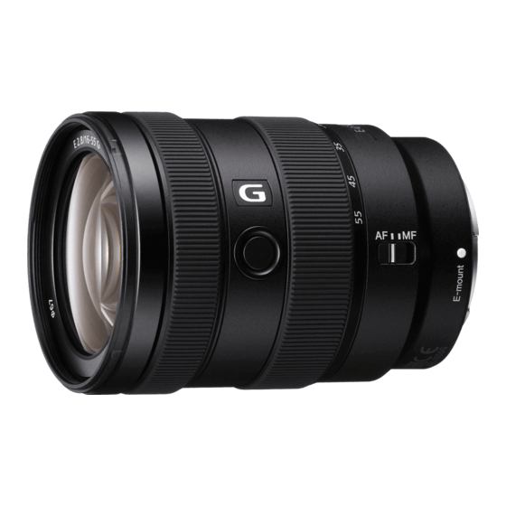
E 16-55mm F2.8 G
(SEL1655G)
16-55
24-82.5
1
(mm)
12-17
2
83°-29°
3
(m (feet)) 0.33 (1.09)
f/22
67
73 × 100
(2 7/8 × 4)
494 (17.5)
No
SEL1655G
(E 2.8/16-55 G) (E 16-55mm F2.8 G)
SPECIFICATIONS
*
1
This is the equivalent focal length in 35mm format
when mounted on an Interchangeable Lens Digital
Camera equipped with an APS-C sized image sensor.
*
2
Angle of view is the value for Interchangeable Lens
Digital Cameras equipped with an APS-C sized image
sensor.
*
3
Minimum focus is the distance from the image sensor
to the subject.
• Depending on the lens mechanism, the focal length
may change with any change in shooting distance.
The focal lengths given above assume the lens is
focused at infinity.
Included items
(The number in parentheses indicates the number
of pieces.)
Lens (1), Front lens cap (1), Rear lens cap (1),
Lens hood (1), Lens case (1), Set of printed
documentation
Design and specifications are subject to change
without notice.
and
are trademarks of Sony Corporation.
INTERCHANGEABLE LENS
US Model
Canadian Model
AEP Model
Chinese Model
E-mount
SYS SET
Advertisement
Table of Contents

Related Manuals for Sony SEL1655G


Summary of Contents for Sony SEL1655G
- Page 1 Conditions of Use: Please use this information only for the purpose of performing repair, maintenance and/or confi guration services of the Sony products (hereinafter the “Repair services”) under the service agreement entered into with the Sony group company (hereinafter the “Service agreement”). Using this information for any purpose other than the purpose described foregoing is forbidden.
-
Page 2: Service Note
DE FONCTIONNEMENT. NE REMPLACER CES COMPO- • Be sure to control soldering iron tips used for unleaded solder SANTS QUE PAR DES PIÈCES SONY DONT LES NUMÉ- and those for leaded solder so they are managed separately. ROS SONT DONNÉS DANS CE MANUEL OU DANS LES Mixing unleaded solder and leaded solder will cause detach- SUPPLÉMENTS PUBLIÉS PAR SONY. - Page 3 2020/02/04 22:49:28 (GMT+09:00) SEL1655G 1-5. NOTE ON REPLACEMENT OF MAIN BOARD To replace the Main Board (CL-1075 board), connect the E-mount lens to the ILCE-6300, and read/write of the adjustment data in the following procedure. • Before main board replacement “Read/Write Select” of Lens adjustment program (SEL1655G_ Service_Tool) is set to [Read] to implement the [AjustData- Backup].
-
Page 4: Disassembly And Assembly
2020/02/04 22:49:28 (GMT+09:00) SEL1655G 2. DISASSEMBLY & ASSEMBLY OPERATION NOTES Make sure that the conductive side of a flexible board does not have any stain or foreign materials. Do not touch the conductive side of flexible boards with bare hands. Plug in a flexible board straight, fully into the connector until it reaches the end inside. (Fig. 1, Fig. 2, Fig. 3) - Page 5 2020/02/04 22:49:28 (GMT+09:00) SEL1655G 2-1. CONSTITUTION DIAGRAM Red arrow direction : Shown the front (lens) side Black arrow direction : Shown the rear (mount) side back adjustment washer 1st group assy 1st moving frame assy front outer assy cam follower A cam follower A...
- Page 6 2020/02/04 22:49:28 (GMT+09:00) SEL1655G 2-2. DISASSEMBLY • Disassembled in the order shown in the fl owchart below. 2-2-1. DISASSEMBLY FLOW FRONT SIDE (LENS SIDE) REAR SIDE (MOUNT SIDE) 2-2-2. ORNAMENT PLATE 2-2-5. MOUNT ASSY RESOLVING POWER (Page 2-4) (Page 2-6) (PARTIAL BLUR) ADJUSTMENT RESOLVING POWER 2-2-3.
- Page 7 2020/02/04 22:49:28 (GMT+09:00) SEL1655G Note: Disassemble in the order indicated by the numbers assigned to the parts in the fi gures such as 1. 2-2-2. ORNAMENT PLATE 1 Soak alcohol between the Note 1: Remove the ornament plate using the service tool.
- Page 8 2020/02/04 22:49:28 (GMT+09:00) SEL1655G 2-2-3. FRONT OUTER ASSY 1 three tapping screws (1.4 1 three tapping screws (1.4 screw position 2 front outer assy boss Note: Take care not to damage the boss. front outer assy screw position (from front (lens) side)
- Page 9 2020/02/04 22:49:28 (GMT+09:00) SEL1655G 2-2-5. MOUNT ASSY 1 four tapping screws (2 mount block 4 mount assy 2 Lift up the mount assy Note 1: Take care not to damage the flexible board. Note 2: Take care not to lose the M pin A and the ring click2 spring.
- Page 10 2020/02/04 22:49:28 (GMT+09:00) SEL1655G 2-2-7. REAR COVER ASSY 1 four tapping screws (1.7 screw position 2 rear cover assy rear cover assy screw position (from rear (mount) side) rear (mount) side front (lens) side 2-2-8. TORQUE ADJUST PLATE BLOCK torque adjust sheet...
- Page 11 2020/02/04 22:49:28 (GMT+09:00) SEL1655G 2-2-9. ZMR ASSY 2 ZMR assy (potentiometer part) Note: Take care not to damage the flexible board. 1 two tapping screws (1.4 rear (mount) side front (lens) side 3 two tapping screws (1.4 3.5) 4 ZMR assy (ZMR holder part) Note: Take care not to damage the flexible board.
- Page 12 2020/02/04 22:49:28 (GMT+09:00) SEL1655G 2-2-10. ZOOM RING RUBBER (B) 1 zoom ring rubber (B) 2 FPC repair tape A (7-7) rear (mount) side 3 guard tape Z front (lens) side SYS SET...
- Page 13 2020/02/04 22:49:28 (GMT+09:00) SEL1655G 2-2-11. ZOOM RING ASSY 1 cam pin A zoom linkage pin 1 cam pin A rear (mount) side front (lens) side 2 Rotate the zoom ring assy in the direction of the arrow from the hole to the position where you can see the zoom linkage pin.
- Page 14 2020/02/04 22:49:28 (GMT+09:00) SEL1655G 2-2-12. MID COVER ASSY 2 Remove by rotating the mid cover stopper in the direction of the arrow. STA barrel assy rear (mount) side 1 Pour alcohol into the gap between the mid cover stopper and STA barrel assy.
- Page 15 2020/02/04 22:49:28 (GMT+09:00) SEL1655G 2-2-13. APPEARANCE BLOCK 1 three screws (M1.7 3.5) screw position 2 appearance block Note: Take care not to damage the flexible board. appearance block (from rear (mount) side) rear (mount) side front (lens) side 2-2-14. FOCUS RING RUBBER (B)
- Page 16 2020/02/04 22:49:28 (GMT+09:00) SEL1655G 2-2-15. FOCUS RING ASSY 3 focus ring key 2 tapping screw (1.4 2.5) 3 focus ring key 2 tapping screw (1.4 2.5) focus ring assy 2 tapping screw (1.4 2.5) 3 focus ring key 2 tapping screw (1.4 2.5)
- Page 17 2020/02/04 22:49:28 (GMT+09:00) SEL1655G 2-2-16. 6TH GROUP ASSY 1 three screws (M1.7 3.5) 2 6th group assy 3 three back adjustment washers Note: Take note of the amount of washers. rear (mount) side front (lens) side 2-14 SYS SET...
- Page 18 2020/02/04 22:49:28 (GMT+09:00) SEL1655G 2-2-17. 3-5 GROUP BLOCK 3 cam pin 1 two screws (M1.4 2 Lift up the main FPC plate. 4 cam follower A 3 cam pin 3 cam pin 4 cam follower A rear (mount) side 4 cam follower A...
- Page 19 2020/02/04 22:49:28 (GMT+09:00) SEL1655G 2-2-18. IRIS, 3-5 GROUP ASSY 3 iris cover front (lens) side rear (mount) side 2 two claws 2 claw 6 iris 1 iris flexible board 4 Lift up the iris. 7 three gom bushs B Note 2: The gom bush B may be stuck to iris.
- Page 20 2020/02/04 22:49:28 (GMT+09:00) SEL1655G 2-2-19. 1ST MOVING FRAME ASSY 1 cam pin A 1 cam pin A 1 cam pin A rear (mount) side front (lens) side 3 two cam pin shaft (M) blocks 3 cam pin shaft (M) block cam pin shaft (M)
- Page 21 2020/02/04 22:49:28 (GMT+09:00) SEL1655G 2-2-20. 2ND LENS BARREL ASSY, Z CAM BAR ASSY Note 1: The 2nd shading sheet and the G7 mask 3 2nd lens barrel assy can not be replaced. Be careful not to peel it off or damage it.
- Page 22 2020/02/04 22:49:28 (GMT+09:00) SEL1655G 2-3. ASSEMBLY • Assemble in the order shown in the fl owchart below. 2-3-1. ASSEMBLY FLOW Z CAM BAR ASSY 2-3-2. CAM FOLLOWER I_A (4.0), 3-5 GROUP ASSY ZM STRAIGHT 2G MASK (Page 2-20) 2-3-5. MAIN FPC PLATE 2-3-3.
- Page 23 2020/02/04 22:49:28 (GMT+09:00) SEL1655G Assemble in the order indicated by the numbers assigned to the parts in the fi gures such as 1. Note: 2-3-2. CAM FOLLOWER I_A (4.0), ZM STRAIGHT 2G MASK 2 three cam followers I_A (4.0) 3 cam pin I_A Note 1: When replacing the cam follower I_A (4.0),...
- Page 24 2020/02/04 22:49:28 (GMT+09:00) SEL1655G 2-3-3. 2ND LENS BARREL ASSY 3 Install the 2nd lens barrel assy Note 1: The 2nd shading sheet and the G7 mask 2 Align the 2nd lens barrel assy to the to the Z cam bar block. can not be replaced.
- Page 25 2020/02/04 22:49:28 (GMT+09:00) SEL1655G 2-3-4. 1ST MOVING FRAME ASSY 4 cam pin shaft (M) block 1 Align the groove on the Z cam bar block. Note 2: Install the cam pin shaft (M) as shown in the direction of figure below. rear (mount) side...
- Page 26 2020/02/04 22:49:28 (GMT+09:00) SEL1655G 2-3-5. MAIN FPC PLATE 1 3-5 group assy boss Note 1: A protective part (iris cover and part of 6th lens assy) is attached. When replacing, remove them before use. Note 2: Take care not to damage the boss.
- Page 27 2020/02/04 22:49:28 (GMT+09:00) SEL1655G 2-3-6. IRIS 2 iris 5 Install the iris. 1 Install the gom bush B to the boss. 4 boss 1 Install the gom bush B boss to the boss. 1 Install the gom bush B to the boss.
- Page 28 2020/02/04 22:49:28 (GMT+09:00) SEL1655G 2-3-7. 3-5 GROUP BLOCK 2 Set the lever in the direction 3 Align the lever with the groove inside the Z cam barrel of the arrow. and insert the 3-5 group block. 4 Insert the 3-5 group block to the position shown below.
- Page 29 2020/02/04 22:49:28 (GMT+09:00) SEL1655G 2-3-8. 6TH GROUP ASSY 2 Temporarily fasten the three screws (M1.7 3.5). 1 6th group assy rear (mount) side front (lens) side 3 three back adjustment washers Note 1: Install exactly as recorded during disassembly. 5 Fix the three screws with adhesive bonds.
- Page 30 2020/02/04 22:49:28 (GMT+09:00) SEL1655G 2-3-9. FOCUS RING ASSY 2 focus ring assy 1 STA barrel assy 6 tapping screw (1.4 2.5) (total six pieces) 5 boss 5 boss front (lens) side convex part rear (mount) side 4 focus ring key (total six pieces) Note: Be careful of the direction of installation.
- Page 31 2020/02/04 22:49:28 (GMT+09:00) SEL1655G 2-3-10. FOCUS RING RUBBER (B) 2 focus ring rubber (B) focus ring block guard tape Z pasting reference 1 guard tape Z front (lens) side rear (mount) side 2-3-11. APPEARANCE BLOCK 2 three screws (M1.7 3.5) appearance block...
- Page 32 2020/02/04 22:49:28 (GMT+09:00) SEL1655G 2-3-12. MID COVER ASSY 1 Align the position of the button part and install the mid cover assy. Note: Take care so that the flexible board is not pinched. button part rear (mount) side front (lens) side 3 Install by rotating the mid cover stopper in the direction of the arrow.
- Page 33 2020/02/04 22:49:28 (GMT+09:00) SEL1655G 2-3-13. ZOOM RING ASSY STA barrel assy 1 Apply grease to 3 places (all around) of the STA barrel assy. G-85 rear (mount) side front (lens) side 2 Align the three convex parts with the three notches to install the zoom ring assy.
- Page 34 2020/02/04 22:49:28 (GMT+09:00) SEL1655G 2-3-14. ZOOM LINKAGE PIN 1 Rotate "55" on the zoom ring assy to the G badge position and align the hole with the cam groove. hole “55” zoom ring assy zoom ring assy rear (mount) side cam groove...
- Page 35 2020/02/04 22:49:28 (GMT+09:00) SEL1655G 2-3-15. ZOOM RING RUBBER (B) zoom ring assy guard tape Z pasting reference 1 guard tape Z rear (mount) side front (lens) side 3 zoom ring rubber (B) 2 FPC repair tape A (7-7) 2-32 SYS SET...
- Page 36 2020/02/04 22:49:28 (GMT+09:00) SEL1655G 2-3-16. ZMR ASSY 3 two bosses 4 two tapping screws (1.4 3.5) 2 ZMR assy (ZMR holder part) 1 Set the zoom ring Note: Take care not to damage to the TETE end. the flexible board. rear (mount) side...
- Page 37 2020/02/04 22:49:28 (GMT+09:00) SEL1655G 2-3-17. TORQUE ADJUST PLATE 3 Align the hole positions and install the torque adjust sheet. Note: Make sure that torque adjust rubber does not protrude from the torque adjust sheet. hole hole 2 Place the torque adjust rubber on the center of the torque adjust plate.
- Page 38 2020/02/04 22:49:28 (GMT+09:00) SEL1655G 2-3-19. CL-1075 BOARD 2 CL-1075 board 3 MR flexible board 5 zoom flexible board 1 Crease the main flexible board. : Mountain fold 4 main flexible board : Valley fold rear (mount) side front (lens) side main flexible board...
- Page 39 2020/02/04 22:49:28 (GMT+09:00) SEL1655G 2-3-20. MOUNT RUBBER 1 mount block 2 three C tapes Note: C tapes cannot be reused. Be sure to replace them with new parts. 3 mount rubber rear (mount) side front (lens) side 2-36 SYS SET...
- Page 40 2020/02/04 22:49:28 (GMT+09:00) SEL1655G 2-3-21. MOUNT ASSY Note 1: Be careful of the direction of installation. M pin A rear (mount) side 2 M pin A front (lens) side 1 ring click2 spring 2 M pin A 1 ring click2 spring rear (mount) side...
- Page 41 2020/02/04 22:49:28 (GMT+09:00) SEL1655G 2-3-22. 1ST GROUP ASSY 2 Temporarily fasten the three tapping screws (1.7 1 Align the marking with “A” to install the 1st group assy. marking 1st group assy “A” (from front (lens) side) front (lens) side rear (mount) side...
- Page 42 2020/02/04 22:49:28 (GMT+09:00) SEL1655G 2-3-23. FRONT OUTER ASSY 3 three tapping screws (1.4 3 three tapping screws (1.4 1 Align the index and install the front outer assy. index 2 boss front (lens) side index rear (mount) side 2-3-24. ORNAMENT PLATE 3 Paste the ornament plate block...
-
Page 43: Exploded Views
2020/02/04 22:49:28 (GMT+09:00) SEL1655G 3. EXPLODED VIEWS Note: • -XX and -X mean standardized parts, so they may have some diff erence from the original one. • Items marked “*” are not stocked since they are seldom required for routine service. Some delay should be anticipated when ordering these items. - Page 44 2020/02/04 22:49:28 (GMT+09:00) SEL1655G 3-2. MOUNT SECTION Refer to half assy section. Red arrow direction : Shown the front (lens) side Black arrow direction : Shown the rear (mount) side Refer to appearance assy section. (Note 3) (Note 4) (Size 7 7 mm)
- Page 45 2020/02/04 22:49:28 (GMT+09:00) SEL1655G 3-3. APPEARANCE ASSY SECTION Red arrow direction : Shown the front (lens) side Black arrow direction : Shown the rear (mount) side Ref. No. Part No. Description Ref. No. Part No. Description 474116601 MID COVER STOPPER (8005) A5007404A...
- Page 46 2020/02/04 22:49:28 (GMT+09:00) SEL1655G Ver. 1.1 3-4. HALF ASSY SECTION Red arrow direction : Shown the front (lens) side Black arrow direction : Shown the rear (mount) side (Note 1) (Note 1) not supplied (Note 1) (Note 1) (Note 1) (Note 1)
- Page 47 2020/02/04 22:49:28 (GMT+09:00) SEL1655G Ver. 1.1 3-5. SELECTION PARTS Ref. No. 7 BACK ADJUSTMENT WASHER Ref. No. 162 CAM FOLLOWER I_A (4.0) (for resolving power adjustment) Perform an operation check of the relevant locations, and select an This part is for resolving power adjustment.
-
Page 48: Supplied Accessories
2020/02/04 22:49:28 (GMT+09:00) SEL1655G 4. SUPPLIED ACCESSORIES Note: • Items marked “*” are not stocked since they are seldom required for routine service. Some delay should be anticipated when ordering these items. Ref. No. Part No. Description 474118001 MANUAL, INSTRUCTION (JAPANESE, ENGLISH,... - Page 49 2020/02/04 22:49:28 (GMT+09:00) SEL1655G 5. ADJUSTMENTS Note: When disassembled the lens, after the assembly has been completed, perform adjustments by referring to this chapter. 5-1. BEFORE STARTING ADJUSTMENTS 5-1-1. Adjustment Items after Replacing Parts When replacing main parts and boards, adjust or check the items indicated by z in the following table.
- Page 50 2020/02/04 22:49:28 (GMT+09:00) SEL1655G 5-1-2. Adjustment/Check Procedure Flow Chart After the parts replacement Lens adjustment program (1) PRESET ADJ 5-5. SEL1655G_ Service_Tool (2) PRESET2 ADJ 5-2-3. Optical Axis 5-2-2. Optical Axis Adjustment Check Peripheral/ 5-3-6. Partial Blur Check Partial Blur 5-3. Resolving Power...
- Page 51 2020/02/04 22:49:28 (GMT+09:00) SEL1655G 5-1-3. List of Service Tools and Equipment Service Tools/Equipments Part No. Fig. No. Remarks LensLauncher_Ver[][][][].exe LensLauncher for DF ― ― Version: 2.1.2 or higher Partial_blur_adjustment_SEL1655G_Ver[][][][].exe DF Tool ― ― Version: 1.0.1 or higher ServiceAppLauncher_Ver[][][].zip Version: 1.0.1 or higher ServiceAppLauncher ―...
- Page 52 2020/02/04 22:49:28 (GMT+09:00) SEL1655G Service Tools/Equipments Part No. Fig. No. Remarks The SeusEX must be installed in the PC. The Excel 2010 or later must be installed in the PC. Windows 10 recommended USB port: USB 2.0 recommended (also compatible with 1.1) Personal computer ―...
- Page 53 2020/02/04 22:49:28 (GMT+09:00) SEL1655G Service Tools/Equipments Part No. Fig. No. Remarks Combination of the A-E mount conversion attachment and the E-Mount A-E mount attachment J-6082-798-A Extension Jig A-E mount conversion attachment J-6082-845-A E-Mount Extension Jig J-6082-799-A Flange back gauge (43.50 mm) J-6082-608-A Extension Jig (47.00 mm)
- Page 54 2020/02/04 22:49:28 (GMT+09:00) SEL1655G 5-2. OPTICAL AXIS CHECK/ Setting of the Flange Back Tester 1. Set the equipment as shown in the following figure. ADJUSTMENT Dial Gauge A-mount attachment (Min. scale: 0.01 mm) 5-2-1. Setting/Preparation of the Flange Back (f’F) Objective lens (10x)
- Page 55 • Shake Compensation: OFF runs normally and USB is connectable. • Aperture: Open Note 2: For adjustment of the SEL1655G, prepare a version 1.1.4.S or 2. Attach the extension jig (47.00 mm) to the objective lens (10x) higher of the BLG-TestProgram.
- Page 56 2020/02/04 22:49:28 (GMT+09:00) SEL1655G 5. When starting and finishing the BLG-TestProgram, perform the following procedure. • Starting the BLG-TestProgram • Finishing the BLG-TestProgram Procedure of Starting Procedure of Finishing (1) Mount a checking lens to the lens mount block. (1) Click [Power] to turn off the power to the lens.
- Page 57 2020/02/04 22:49:28 (GMT+09:00) SEL1655G 6. Start the lens adjustment program “BLG-TestProgramV[][][].exe”. 7. When [Open] is clicked and communication between personal computer and B-L Control Box is connected, the button name changes to [Close] and the [Power] button is made active. 8. Click [Power] to supply power to the checking lens.
- Page 58 2020/02/04 22:49:28 (GMT+09:00) SEL1655G 9. Align the plane mirror with the center projected image on the screen, and confirm again that the reflected light illuminates the center of the checking lens. If the reflected light position is deviated, re-adjust the lens projector position.
- Page 59 2020/02/04 22:49:28 (GMT+09:00) SEL1655G 5-2-2. Optical Axis Check Checking Procedure 1. Adjust the optical axis while observing the microscope until the chart image can be seen in the center. 2. Perform steps (1) to (6) and check that the AS and CB values are within specifications.
-
Page 60: Optical Axis Adjustment
2020/02/04 22:49:28 (GMT+09:00) SEL1655G 7. Apply the adhesive bond (B-110) to the following 3 places. 5-2-3. Optical Axis Adjustment Note: Optical Axis Adjustment is done by moving the lens in the 3-5 B-110 group assy. Refer to “2-2. DISASSEMBLY”, disassemble the lens, and move the lens in the 3-5 group assy using the adjuster pin. -
Page 61: Setting Procedure
2020/02/04 22:49:28 (GMT+09:00) SEL1655G 5-3. RESOLVING POWER CHECK 5-3-1. Setting/Preparation of the Lens Test Projector Preparations of Using a Camera (General E-mount Interchangeable Lens Digital Camera) Equipment and Tools • Camera (General E-mount interchangeable lens digital camera) • Lens Test Projector (F) •... - Page 62 Note 1: Personal computer must have the condition that Windows 10 runs normally and USB is connectable. Note 2: For adjustment of the SEL1655G, prepare a version 1.1.4.S or higher of the BLG-TestProgram. Note 3: Attach the E-mount FF/APSC jig for Lens Test Projector (F) suitable for the type of checking lens (FF/APSC) to the Lens Test Projector.
- Page 63 2020/02/04 22:49:28 (GMT+09:00) SEL1655G (2) Starting and Finishing the BLG-TestProgram Starting the BLG-TestProgram Procedure of Finishing 1. Mount a checking lens to the lens mount block. 1. Click [Power] to turn off the power to the lens. 2. Connect the D-sub 15-pin cable to the lens mount block, and 2.
- Page 64 2020/02/04 22:49:28 (GMT+09:00) SEL1655G (3) Setting Method Setting Procedure 1. Start the lens adjustment program “BLG-TestProgramV[][][].exe”. 2. When [Open] is clicked and communication between personal computer and B-L Control Box is connected, the button name changes to [Close] and the [Power] button is made active.
- Page 65 2020/02/04 22:49:28 (GMT+09:00) SEL1655G 4. Align the plane mirror with the center projected image on the screen, and confirm again that the reflected light illuminates the center of the checking lens. If the reflected light position is deviated, re-adjust the lens projector position.
-
Page 66: Checking Procedure
2020/02/04 22:49:28 (GMT+09:00) SEL1655G 5-3-2. Projective Resolving Power Check Reference value: Number of projective resolving power lines (lines/mm) Focal length f Distance (m) (mm) Peripheral (y' = 10) Peripheral (y' = 12) Center (y' = 0) 0.64 0.96 More than More than... - Page 67 2020/02/04 22:49:28 (GMT+09:00) SEL1655G 4. Read the value of the number of projective resolving power lines (maximum resolving power) of the center projected image (y’ = 0). 5. Read the value (the number of projective resolving power lines) of the thinnest line (resolution limit) that allows recognition of contrast of the sagittal (S) image and meridional (M) image (three lines) of the peripheral projected image (y’...
-
Page 68: Equipment And Tools
2020/02/04 22:49:28 (GMT+09:00) SEL1655G 5-3-3. Setting/Preparation of the Resolution Picture Frame Check 1. Select the “Diag. + Square Grid” from the “Grid Line” in the Check Chart camera menu items. For this lens, it is necessary to check the photographic resolving 2. Confirm that the following standard are satisfied when checking power with two kinds of focal length (16 mm, 55 mm). - Page 69 2020/02/04 22:49:28 (GMT+09:00) SEL1655G 5-3-4. Photographic Resolving Power Check 5-3-5. Preparation of DF Tool Equipment and Tools Equipment and Tools • Camera (ILCE-7RM2/7M3/7RM3) • Camera (ILCE-7RM2/7M3/7RM3) • Resolution check chart (ILC) • Personal Computer (See Note 1) • Tape measure • HASP key (SeusEX) •...
- Page 70 2020/02/04 22:49:28 (GMT+09:00) SEL1655G 5. The installer confirm screen appears, then click the [Next] button (1) Installation of LensLauncher for DF to start the installation. Prepare a version 2.1.2 or higher of the LensLauncher for DF. Note: Perform the installation by administrator privileges.
-
Page 71: Procedure Of Installation
2020/02/04 22:49:28 (GMT+09:00) SEL1655G 5. The installer confirm screen appears, then click the [Next] button (2) Installation of DF Tool to start the installation. Prepare a version 1.0.1 or higher of the DF Tool. Note: Perform the installation by administrator privileges. Do not change the installation folder. - Page 72 2020/02/04 22:49:28 (GMT+09:00) SEL1655G (3) Method of Starting and Finishing for DF Tool Procedure of Finishing SeusEX will start when the DF Tool is started. 1. Click the [CLOSE] button on the RACS screen to close the RACS screen. Procedure of Starting 2.
- Page 73 2020/02/04 22:49:28 (GMT+09:00) SEL1655G 5. When writing the washer thickness, enter the washer thickness (4) SHIM DATA W/R and click the [SHIM DATA <<WRITE>>] button. The washer thickness data saved on the main board can be read/ written. Read/Write Procedure 1. Click the [SHIM DATA W/R] button on the DF Tool.
- Page 74 2020/02/04 22:49:28 (GMT+09:00) SEL1655G 7. The following screen is displayed, set the SteadyShot of camera’s 5-3-6. Partial Blur Check (DF Tool) MENU items to “OFF” and press the ENTER key. (1) Shooting Shoot to total of 42 images of WIDE: 21 images and TELE: 21 im- ages for the partial blur check.
- Page 75 2020/02/04 22:49:28 (GMT+09:00) SEL1655G 13. When shooting is completed, “CAPTURE OK” is displayed. (3) Partial Blur Check Press the ENTER key. Analyze 42 captured image files and check the partial blur. Checking Procedure 1. Remove the SD card from the camera and capture the 42 image files to the PC.
- Page 76 2020/02/04 22:49:28 (GMT+09:00) SEL1655G 4. Analysis of each image file is automatically started. 8. Analysis of each image file is automatically started. [][][][] [][][][] [][][][][][][][][][][] [][][][][][][][][][][] 5. When the analysis is completed, “<TELE> OK” is displayed on 9. When the analysis is completed, “<WIDE> OK” is displayed on the message.
- Page 77 2020/02/04 22:49:28 (GMT+09:00) SEL1655G 11. If there is a priority zoom position in partial blur adjustment, set 16. Click the [START SHIM CALCULATION] button and the the zoom position in the adjust balance select area. ShimCaluc screen is appeared. Input the recorded current washer thickness in the current area.
- Page 78 2020/02/04 22:49:28 (GMT+09:00) SEL1655G 5. Click the [SHIM DATA <<WRITE>>] button. 5-3-7. Write the Thickness of Washer (DF Tool) After performing the “(2) Curvature Adjustment” of “5-4-2. Resolv- ing Power Adjustment (mount assy)”, the thickness of the washer needs to be stored on the main board of the lens.
- Page 79 2020/02/04 22:49:28 (GMT+09:00) SEL1655G 4. Replace the back adjustment washer so that it has the specified 5-4. RESOLVING POWER ADJUSTMENT thickness. Note: Resolving Power Adjustment is done by increasing or decreas- back adjustment ing the thickness of the washer. washer (ShimB) Refer to “2-2. DISASSEMBLY”, disassemble the lens, and change the thickness of the washer.
-
Page 80: Adjusting Procedure
2020/02/04 22:49:28 (GMT+09:00) SEL1655G 5-4-2. Resolving Power Adjustment (mount assy) (2) Curvature Adjustment Adjusting Procedure (1) Partial Blur Adjustment 1. Remove the mount assy, referring to the “2-2. DISASSEMBLY”. 2. Increase or decrease equally the thickness of the four back washer Adjusting Procedure to adjust the curvature. - Page 81 2020/02/04 22:49:28 (GMT+09:00) SEL1655G 5-5. SEL1655G_Service_Tool 5-5-1. Preparations Set the equipment and the checking lens as shown below. Equipment and Tools When the subject is a small pattern box • Personal Computer (See Note 1, 2) • HASP key (SeusEX) Small pattern box (PTB-1450) •...
- Page 82 2020/02/04 22:49:28 (GMT+09:00) SEL1655G 5. The installer confirm screen appears, then click the [Next] button (1) Installation of ServiceAppLauncher to start the installation. Prepare a version 1.0.1 or higher of the ServiceAppLauncher. Note: Perform the installation by administrator privileges. Do not change the installation folder.
- Page 83 2020/02/04 22:49:28 (GMT+09:00) SEL1655G 5. The installer confirm screen appears, then click the [Next] button (2) Installation of EEPROM_LogViewer to start the installation. Prepare a version 1.0.0 or higher of the EEPROM_LogViewer. Note: Perform the installation by administrator privileges. Do not change the installation folder.
- Page 84 2020/02/04 22:49:28 (GMT+09:00) SEL1655G 5. The installer confirm screen appears, then click the [Next] button (3) Installation of SEL1655G_Service_Tool to start the installation. Prepare a version 1.0.0 or higher of the SEL1655G_Service_Tool. Note: Perform the installation by administrator privileges. Do not change the installation folder.
-
Page 85: Precautions For Use
C drive. • ErrorCodeList.xlsx [Message Clear] button Message area 3. Select “SEL1655G” from the “Select Lens model”, and click [OK] to start the SEL1655G_Service_Tool. [].[].[].[] • When the error occurs in the flange back adjustment, the Error- CodeDisplay screen is appeared. -
Page 86: Adjusting Method
2020/02/04 22:49:28 (GMT+09:00) SEL1655G 4. After get of the zoom end AD value is completed, starts the 5-5-4. Adjustment Method of Each Item switch inspection. Message screen is displayed in the following. Operate the focus hold button in accordance with the message. - Page 87 2020/02/04 22:49:28 (GMT+09:00) SEL1655G 7. Starts the focusing ring adjustment/inspection. Set for the focus- 14. When the focusing ring adjust/inspection is completed, automatic ing ring to the position of the tape etc. stuck by “Preparations” adjustment of the focus MR sensor is started.
- Page 88 2020/02/04 22:49:28 (GMT+09:00) SEL1655G 18. When the ENTER key is pressed, message screen is displayed (2) PRESET2 ADJ in the following. Set the zooming ring to the WIDE end (focal • Perform focus actuator inspection. length: 16 mm). Subject Not required Operation on Lens side...
- Page 89 2020/02/04 22:49:28 (GMT+09:00) SEL1655G 4. When the ENTER key is pressed, automatically starts the adjust- (3) F NO ADJ ments. • Adjust the F number. Small pattern box (PTB-1450) Subject + Clear chart • Zooming ring Operation on Lens side • Focus mode switch...
- Page 90 2020/02/04 22:49:28 (GMT+09:00) SEL1655G 4. “PLEASE CHANGE TO - WIDE” is displayed, set the zooming (4) FB ADJ ring to the WIDE end (focal length: 16 mm). • Adjust the flange back of inner focus lens. Flange back adjustment jig Subject + FB adjustment chart (10 mm) •...
- Page 91 2020/02/04 22:49:28 (GMT+09:00) SEL1655G 7. When the ENTER key is pressed, automatic adjustment of TELE 14. Rotate the zooming ring to the WIDE side until the background end is started. color of the value (hexadecimal number) at the lower left of the window changes to light blue.
- Page 92 2020/02/04 22:49:28 (GMT+09:00) SEL1655G 3. “Select the AF.” is displayed, set the focus mode switch to the (5) Focus Shift Adjustment • The focus shift due to change in the F number is corrected. • Flange back adjustment jig + Subject FB adjustment chart (10 mm) •...
- Page 93 2020/02/04 22:49:28 (GMT+09:00) SEL1655G 9. After the automatic adjustment is completed, message screen 15. When the ENTER key is pressed, message screen is displayed in is displayed in the following. Rotate the zooming ring to the the following. Set the flange back adjustment jig on the subject.
-
Page 94: Checking Method
2020/02/04 22:49:28 (GMT+09:00) SEL1655G 4. “Confirm the image is in focus while zoom. Start” is displayed, (6) FB CHK press the ENTER key. • Check the focus position. Flange back adjustment jig Subject + FB adjustment chart (10 mm) • Focus mode switch Operation on Lens side •... - Page 95 2020/02/04 22:49:28 (GMT+09:00) SEL1655G 4. Operate the zooming ring and confirm that there is no center (7) IMAGE CHK shifting, image shaking or image jumping on the camera monitor. • Check that there is no center shifting, image shaking or image When the confirmation is complete, press the ENTER key.
- Page 96 2020/02/04 22:49:28 (GMT+09:00) SEL1655G (8) ROM CHECK (10) Write the serial number • Check the data stored on the Main Board. • Write the lens serial number on the Main board. Subject Not required Subject Not required Operation on Lens side Not required...
- Page 97 2020/02/04 22:49:28 (GMT+09:00) SEL1655G (11) FOCUS Erase (13) Erase the error log • Erase the device data of the focus stored on the Main Board. • Erase the error log stored on the Main Board. Subject Not required Subject Not required Operation on Lens side...
-
Page 98: Saving Method
2020/02/04 22:49:28 (GMT+09:00) SEL1655G (14) Check the log information Checking Method • It can save/check the log information of the Main board. 1. Click the [Log Viewer] button, EEPROM_LOG_Viewer starts Subject Not required Operation on Lens side Not required Shooting Mode of the camera P mode (Program Auto) Saving Method 1. -
Page 99: Revision History
2020/02/04 22:49:28 (GMT+09:00) SEL1655G Revision History Ver. Date History Contents 2019.09 Official Release — 2020.01 Revised-1 • Correction of repair parts (Ref. No. 153) (Page 3-4, 3-5) SYS SET...
Need help?
Do you have a question about the SEL1655G and is the answer not in the manual?
Questions and answers