Sign In
Upload
Download
Table of Contents
Contents
Add to my manuals
Delete from my manuals
Share
URL of this page:
HTML Link:
Bookmark this page
Add
Manual will be automatically added to "My Manuals"
Print this page
×
Bookmark added
×
Added to my manuals
Manuals
Brands
Sony Manuals
Camera Accessories
FCB-EV7520A
Technical manual
Sony FCB-EV7520A Technical Manual
Color camera module
Hide thumbs
1
2
3
4
5
6
7
8
9
10
11
12
13
14
15
16
17
18
19
20
21
22
23
24
25
26
27
28
29
30
31
32
33
34
35
36
37
38
39
40
41
42
43
44
45
46
47
48
49
50
51
52
53
54
55
56
57
58
59
60
61
62
63
64
65
66
67
68
69
70
71
72
73
74
75
76
77
Table Of Contents
78
page
of
78
Go
/
78
Contents
Table of Contents
Bookmarks
Table of Contents
Table of Contents
Features
Precautions
Operation and Storage Locations
Phenomena Specific to CMOS Image Sensors
Rolling Shutter
Locations of Controls
Basic Functions
Overview of Functions
Timing Chart
AF Sensitivity
Auto Focus Mode
Focus
Zoom
Auto Exposure Mode (AE)
Gain Limit Setting
Shutter Priority
White Balance (WB)
AE – Manual
AE – Shutter Priority
Spot Exposure Mode
Aperture Control
Backlight Compensation
Exposure Compensation
Slow AE (Auto Exposure)
Defog Mode
High Sensitivity Mode/Flicker Reduction
HLC (Highlight Correction)
Visibility Enhancer (VE)
Contrast Adjustment Function
Image Stabilizer
Low-Illumination Chroma Suppress Mode
Temperature Reading Function
Auto ICR Mode/Camera ID
Custom Color Gain/Custom Color Phase
ICR (IR Cut-Removable) Mode
Picture Effect
Custom Preset
Memory (Position Preset)
Register Setting
User Memory Area
Title Display
Details of Setting Commands
Privacy Zone Masking Function
Non Interlock Mask
Parameters
Set PTZ Mask
Frames
Motion Detection (MD) Function
Setting Pan/Tilt Angle
Sending Alarms
Setting Commands
Extended Commands
User’s Updating
Update Procedure
Finalizing Procedure
Eclipse
Spectral Sensitivity Characteristics
Initial Settings and Backup of Camera
Lens
Mode Condition
Exposure
White Balance
Others
Command List
VISCA/RS-232C Commands
VISCA Communication Specifications
VISCA Packet Structure
Command and Inquiry
Socket Number
Command Execution Cancel
Responses for Commands and Inquiries
VISCA Device Setting Command
For VISCA Network Administration
VISCA Interface Command
VISCA Interface and Inquiry
VISCA Command/Acknowledge Protocol
VISCA Camera-Issued Messages
Acknowledge/Completion Messages
Error Messages
Network Change Message
FCB Camera Commands
Inquiry Command List
Block Inquiry Command List
VISCA Command Setting Values
Exposure Control
Digital Zoom Combine Mode
Zoom Ratio and Zoom Position
Zoom Separate Mode
Lens Control
Wide/Tele Limit Setting
Temperature Reading Conversion Value (Reference Value)
Register Setting Table
Specifications
Interface
LVDS Pixel Data Format
LVDS Receiver Circuit Example (Single Output)
LVDS Receiver IC (E.g., THC63LVD104C)
LVDS Receiver Circuit Example
LVDS Receiver IC - Pin Assigment Single Mode LVDS Input - CMOS Output
LVDS Receiver Circuit Example (Double Output)
LVDS Receiver IC (E.g., THC63LVD1024, BU90R102)
Cable Reference Specifications (Crossover)
DIGITAL Image Output Y, Cb, Cr 4:2:2 FORMAT
Color Coding Complies with BT709
Synchronized Codes
Interlace System (Comparable to SMPTE 274 M)
Progressive System (Comparable to SMPTE 274 M, 296 M)
Dimensions
Label Drawings
Pin Assignment
Advertisement
Quick Links
1
Features
2
Visca/Rs-232C Commands
3
Fcb Camera Commands
4
Specifications
Download this manual
D-023-100-11(1)
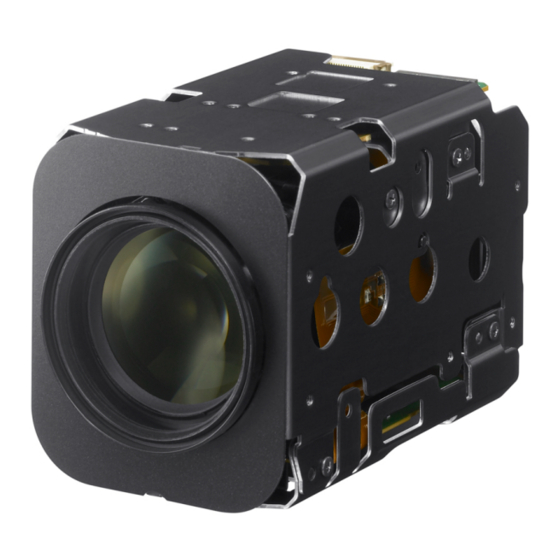
Color Camera Module
Technical Manual
FCB-EV7520A
FCB-CV7520A
2018 Sony Corporation
Table of
Contents
Previous
Page
Next
Page
1
2
3
4
5
Advertisement
Table of Contents
Need help?
Do you have a question about the FCB-EV7520A and is the answer not in the manual?
Ask a question
Questions and answers
Related Manuals for Sony FCB-EV7520A
Camera Accessories Sony FCB-IX11A Technical Manual
Sony camera accessories user manual (45 pages)
Camera Accessories Sony EX480CP Technical Manual
Color camera module (65 pages)
Camera Accessories Sony FCB-H10 Technical Manual
Hd color camera unit (38 pages)
Camera Accessories Sony FCB-CV7520A Technical Manual
Color camera module (78 pages)
Camera Accessories Sony FCB-EX78BP Technical Manual
Color camera module (63 pages)
Camera Accessories Sony FCB-CX45CP Technical Manual
Color camera module (57 pages)
Camera Accessories Sony Manual FCB-CX11DP Technical Manual
Color camera module (49 pages)
Camera Accessories Sony F23 Operation Manual
Optical fiber camera adapter (32 pages)
Camera Accessories Sony FA-WRC1M Operating Instructions Manual
Wireless radio commander (40 pages)
Camera Accessories Sony FA-WRC1M Manual
Wireless radio commander (18 pages)
Camera Accessories Sony G MASTER FE 14mm F1.8 GM Instructions Manual
(7 pages)
Camera Accessories Sony HD Super Motion HDCU3300R E3 Installation Manual
Hd camera control unit (74 pages)
Camera Accessories Sony HDVF-20A Operation Manual
Hd electronic viewfinder (34 pages)
Camera Accessories Sony CCU-M3P Operating Instructions Manual
Camera control unit (48 pages)
Camera Accessories Sony VCT-870RM Service Manual
(4 pages)
Camera Accessories Sony 870RM - Tripod w/Remote For MiniDV Operating Instructions
Remote control tripod (2 pages)
This manual is also suitable for:
Fcb-cv7520a
Table of Contents
Save PDF
Print
Rename the bookmark
Delete bookmark?
Delete from my manuals?
Login
Sign In
OR
Sign in with Facebook
Sign in with Google
Upload manual
Upload from disk
Upload from URL


Need help?
Do you have a question about the FCB-EV7520A and is the answer not in the manual?
Questions and answers