Table of Contents
Advertisement
Advertisement
Table of Contents

Related Manuals for LTS 83 K-ET Series


Summary of Contents for LTS 83 K-ET Series
- Page 1 Digital Video Recorder Quick Start Guide ...
-
Page 2: Table Of Contents
Digital Video Recorder Quick Start Guide ABLE OF CONTENTS Chapter1 Panels Description ..........................6 1.1 Front Panel ............................6 1.2 Rear Panel ............................8 Chapter 2 Installation and Connections ......................10 2.1 DVR Installation ..........................10 2.2 Hard Disk Installation ......................... 10 2.3 RS‐485 and Controller Connection ..................... 13 2.4 HDD Storage Calculation Chart ......................14 Chapter 3 Menu Operation ..........................16 3.1 Menu Structure ..........................16 ... - Page 3 Digital Video Recorder Quick Start Guide Quick Start Guide About this Manual This Manual is applicable to LTD83XXK‐ET/ETC and LTD85XXK‐ST Series HD‐TVI Digital Video Recorder (DVR). The Manual includes instructions for using and managing the product. Pictures, charts, images and all other information hereinafter are for description and explanation only. The information contained in the Manual is subject to change, without notice, due to firmware updates or other reasons. Please find the latest version in the company website. Please use this user manual under the guidance of professionals. Legal Disclaimer REGARDING TO THE PRODUCT WITH INTERNET ACCESS, THE USE OF PRODUCT SHALL BE WHOLLY AT YOUR OWN RISKS. OUR COMPANY SHALL NOT TAKE ANY RESPONSIBILITES FOR ABNORMAL OPERATION, PRIVACY LEAKAGE OR OTHER DAMAGES RESULTING FROM CYBER ATTACK, HACKER ATTACK, VIRUS INSPECTION, OR ...
- Page 4 Digital Video Recorder Quick Start Guide Regulatory Information FCC Information Please take attention that changes or modification not expressly approved by the party responsible for compliance could void the user’s authority to operate the equipment. FCC compliance: This equipment has been tested and found to comply with the limits for a Class A digital device, pursuant to part 15 of the FCC Rules. These limits are designed to provide reasonable protection against harmful interference when the equipment is operated in a commercial environment. This equipment generates, uses, and can radiate radio frequency energy and, if not installed and used in accordance with the instruction manual, may cause harmful interference to radio communications. ...
- Page 5 Digital Video Recorder Quick Start Guide Applicable Models This manual is applicable to the models listed in the following table. Series Model LTD8304K‐ET 83XXK‐ET LTD8308K‐ET LTD8316K‐ET 83XXK‐ETC LTD8308K‐ETC LTD8504K‐ST 85XXK‐ST LTD8508K‐ST LTD8516K‐ST Symbol Conventions The symbols that may be found in this document are defined as follows. Symbol Description Provides additional information to emphasize or supplement important points of the main text. Indicates a potentially hazardous situation, which if not avoided, could result in equipment damage, data loss, performance ...
- Page 6 Digital Video Recorder Quick Start Guide Safety Instructions Proper configuration of all passwords and other security settings is the responsibility of the installer and/or end‐user. In the use of the product, you must be in strict compliance with the electrical safety regulations of the nation and region. Please refer to technical specifications for detailed information. Input voltage should meet both the SELV (Safety Extra Low Voltage) and the Limited Power Source with 100~240 VAC or 12 VDC according to the IEC60950‐1 standard. Please refer to technical specifications for detailed information. Do not connect several devices to one power adapter as adapter overload may cause over‐heating or a fire hazard. Please make sure that the plug is firmly connected to the power socket. If smoke, odor or noise rise from the device, turn off the power at once and unplug the power cable, and then please contact the service center. Preventive and Cautionary Tips Before connecting and operating your device, please be advised of the following tips: Ensure unit is installed in a well‐ventilated, dust‐free environment. Unit is designed for indoor use only. Keep all liquids away from the device. Ensure environmental conditions meet factory specifications. Ensure unit is properly secured to a rack or shelf. Major shocks or jolts to the unit as a result of dropping it may cause damage to the sensitive electronics within the unit. Use the device in conjunction with an UPS if possible. ...
-
Page 7: Chapter1 Panels Description
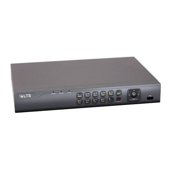
Digital Video Recorder Quick Start Guide Chapter1 Panels Description 1.1 Front Panel The front panel vaires according to different models. Please refer to the actual product. Figure 1‐1 Front Panel Table 1‐1 Description of Front Panel Name Function Description POWER: The POWER indicator turns green when NVR is powered up. STATUS: 1.The light is green when the IR remote control Status Indicators is enabled; 2.The light is red when the function of the composite keys (SHIFT) are used;... - Page 8 Digital Video Recorder Quick Start Guide Name Function Description Enter numeral “5”; Enter letters “JKL”; 5/JKL/EDIT: Delete characters before cursor; Check the checkbox and select the ON/OFF switch; Start/stop record clipping in playback. Enter numeral “6”; 6/MNO/PLAY: Enter letters “MNO”; Playback, for direct access to playback interface. Enter numeral “7”;...
-
Page 9: Rear Panel
Digital Video Recorder Quick Start Guide Name Function Description And in auto sequence view mode, the buttons can be used to pause or resume auto sequence. Receiver for IR remote. IR Receiver 1.2 Rear Panel The rear panel vaires according to different models. Please refer to the actual product. Rear Panel 1 Figure 1‐2 Rear Panel of LTD83XXK‐ET/ETC Rear Panel 2 Figure 1‐3 Rear Panel of LTD85XXK‐ST Table 1‐2 Description of Rear Panel ... - Page 10 Digital Video Recorder Quick Start Guide AUDIO IN RCA connector Connector for RS-485 devices. RS-485 DC 12V power supply. Power Supply Power Switch Switch for turning on/off the device. Ground. Alarm In/Out Connector for alarm input/output. ...
-
Page 11: Chapter 2 Installation And Connections
Digital Video Recorder Quick Start Guide Chapter 2 Installation and Connections 2.1 DVR Installation During installation of the DVR: Use brackets for rack mounting. Ensure ample room for audio and video cables. When routing cables, ensure that the bend radius of the cables are no less than five times than its diameter. Connect the alarm cable. Allow at least 2 cm (≈0.75‐inch) of space between racks mounted devices. Ensure the DVR is grounded. Environmental temperature should be within the range of ‐10 to +55º C, +14 to +131º F. Environmental humidity should be within the range of 10% to 90%. 2.2 Hard Disk Installation Before you start Before installing a hard disk drive (HDD), please make sure the power is disconnected from the DVR. A factory recommended HDD should be used for this installation. One or two SATA hard disks can be installed depending on different models. Tools Required: Screwdriver. As the installation steps of HDD are similar among different models, here we just take an example. Step 1 Remove the cover from the DVR by unfastening the screws on the back and side. ... - Page 12 Digital Video Recorder Quick Start Guide Figure 2‐1 Remove Cover Step 2 Connect one end of the data cable to the motherboard of DVR and the other end to the HDD. Figure 2‐2 Connect Data Cable Step 3 Connect the power cable to the HDD. Figure 2‐3 Connect Power Cable Step 4 Place the HDD on the bottom of the device and then fasten the screws on the bottom to fix the HDD. ...
- Page 13 Digital Video Recorder Quick Start Guide Figure 2‐4 Fix Hard Disk Step 5 Re‐install the cover of the DVR and fasten screws. ...
-
Page 14: Rs-485 And Controller Connection
Digital Video Recorder Quick Start Guide 2.3 RS‐485 and Controller Connection Typical Connection: Figure 2‐5 Controller Connection A To connect PTZ to the DVR: Step 1 Disconnect pluggable block from the RS‐485 terminal block. Step 2 Press and hold the orange part of the pluggable block; insert signal cables into slots and release the orange part. Ensure signal cables are in tight. Step 3 Connect A+ on PTZ to D+ on terminal block and B‐ on controller to D‐ on terminal block. Fasten stop screws. Step 4 Connect pluggable block back into terminal block. Make sure both the controller and DVR are grounded. ... -
Page 15: Hdd Storage Calculation Chart
Digital Video Recorder Quick Start Guide 2.4 HDD Storage Calculation Chart The following chart shows an estimation of storage space used based on recording at one channel for an hour at a fixed bit rate. ... - Page 16 Digital Video Recorder Quick Start Guide Bit Rate Storage Used 128K 160K 192K 224K 256K 112M 320K 140M 384K 168M 448K 196M 512K 225M 640K 281M ...
-
Page 17: Chapter 3 Menu Operation
Digital Video Recorder Quick Start Guide Chapter 3 Menu Operation 3.1 Menu Structure The menu structure varies according to different models. Figure 3‐1 Menu Structure 3.2 Startup and Shutdown Proper startup and shutdown procedures are crucial to expanding the life of the DVR. To start your DVR: Step 1 Check the power supply is plugged into an electrical outlet. It is HIGHLY recommended that an Uninterruptible Power Supply (UPS) be used in conjunction with the device. The Power button on the front panel should be red, indicating the device is receiving the power. ... -
Page 18: Activating Your Device
Digital Video Recorder Quick Start Guide Step 2 Press the POWER button on the front panel. The Power LED should turn blue. The unit will begin to start. After the device starts up, the wizard will guide you through the initial settings, including modifying password, date and time settings, network settings, HDD initializing, and recording. To shut down the DVR: Step 1 Enter the Shutdown menu. Menu > Shutdown Figure 3‐2 Shutdown Step 2 Select the Shutdown button. Step 3 Click the Yes button. 3.3 Activating Your Device Purpose: For the first‐time access, you need to activate the device by setting an admin password. No operation is allowed before activation. You can also activate the device via Web Browser, SADP or client software. Step 1 Input the same password in the text field of Create New Password and Confirm New Password. Figure 3‐3 Set Admin Password ... - Page 19 Digital Video Recorder Quick Start Guide STRONG PASSWORD RECOMMENDED–We highly recommend you create a strong password of your own choosing (Using a minimum of 8 characters, including at least three of the following categories: upper case letters, lower case letters, numbers, and special characters.) in order to increase the security of your product. And we recommend you reset your password regularly, especially in the high security system, resetting the password monthly or weekly can better protect your product. ...
-
Page 20: Using The Unlock Pattern For Login
Digital Video Recorder Quick Start Guide Figure 3‐6 Export GUID Step 5 After exporting GUID, the Attention box pops up as below. Click Yes to duplicate the password or No to cancel it. Figure 3‐7 Duplicate the Password 3.4 Using the Unlock Pattern for Login For the Admin user, you can configure the unlock pattern for device login. After the device is activated, you can enter the following interface to configure the device unlock pattern. Step 1 Use the mouse to draw a pattern among the 9 dots on the screen. Release the mouse when the pattern is done. Figure 3‐8 Draw the Pattern ... -
Page 21: Login And Logout
Digital Video Recorder Quick Start Guide Connect at least 4 dots to draw the pattern. Each dot can be connected for once only. Step 2 Draw the same pattern again to confirm it. When the two patterns match, the pattern is configured successfully. Step 3 You can use the configured unlock pattern for future login. Figure 3‐9 Draw the Unlock Pattern 3.5 Login and Logout 3.5.1 User Login Purpose: If DVR has logged out, you must log in to the device before operating the menu and other functions. Step 1 Select the User Name in the dropdown list. Figure 3‐10 Login Step 2 Input Password. Step 3 Click OK to log in. ... - Page 22 Digital Video Recorder Quick Start Guide Clear‐text password is supported. Click the icon and you can see the clear text of the password. Click the icon again and the content of the password restores invisible. In the Login interface, for the admin, if you have entered the wrong password for 7 times, the account will be locked for 60 seconds. For the operator, if you have entered the wrong password for 5 times, the account will be locked for 60 seconds. Figure 3‐11 User Account Protection for the Admin Figure 3‐12 User Account Protection for the Operator Step 4 (Optional) If you forget the password, click Forget Password to pop up the Import GUID interface. Figure 3‐13 Import GUID 1) Select the GUID file from the USB flash disk and click Import button to pop up the Reset Password interface ...
-
Page 23: User Logout
Digital Video Recorder Quick Start Guide Figure 3‐14 Reset Password 2) Input the new password and confirm the password. 3) Click OK to save the new password. Then the Attention box pops up as shown below. Figure 3‐15 GUID File Imported 4) Click OK and the Attention box as below pops up to remind you to duplicate the password of the device to IP cameras that are connected with default protocol. Click Yes to duplicate the password or No to cancel it. Figure 3‐16 Duplicate the Password If you want to retrieve the password when you forget it, you must export the GUID file first. Once the password is reset, the GUID file becomes ineffective. You can export a new GUID file. 3.5.2 User Logout Purpose: After logging out, the monitor turns to the live view mode and if you want to perform any operations, you need to enter user name and password log in again. Step 1 Enter the Shutdown menu. ... -
Page 24: Using The Setup Wizard
Digital Video Recorder Quick Start Guide Menu > Shutdown Figure 3‐17 Logout Step 2 Click Logout. After you have logged out the system, menu operation on the screen is invalid. It is required to input a user name and password to unlock the system. 3.6 Using the Setup Wizard The Setup Wizard can walk you through some important settings of the device. By default, the Setup Wizard starts once the device has loaded. Check the checkbox to enable Setup Wizard when device starts. Click Next to continue the setup wizard. Follow the guide of the Setup Wizard to configure the system resolution, system date/time, network settings, HDD management, record settings, etc. Figure 3‐18 Wizard 3.7 Viewing Signal Input Status 5 MP long distance transmission is available for LTD85XXK‐ST series DVR. Step 1 Enter the Signal Input Status interface. Menu > Camera > Signal Input Status ... -
Page 25: Network Settings
Digital Video Recorder Quick Start Guide Figure 3‐19 View Signal Input Type Step 2 You can enable 5 MP Long Distance Transmission for the HD and AHD signal input. Follow the steps below to enable the function. 1) Click to enter the 5 MP Long Distance Transmission Settings interface. Figure 3‐20 5 MP Long Distance Transmission Settings 2) Check the checkbox to enable 5 MP Long Distance Transmission of the selected channel. 3) Click Apply to save the settings and OK to return to the Signal Input Status interface. 3.8 Network Settings Purpose: Network settings must be properly configured before you operate DVR over network. Step 1 Enter the Network Settings interface. Menu > Configuration > Network ... -
Page 26: Adding Ip Cameras
Digital Video Recorder Quick Start Guide Figure 3‐21 Network Settings Step 2 Select the General tab. Step 3 In the General Settings interface, you can configure the following settings: NIC Type, IPv4 Address, IPv4 Gateway, MTU and DNS Server. If the DHCP server is available, you can check the checkbox of DHCP to automatically obtain an IP address and other network settings from that server. Step 4 After having configured the general settings, click the Apply button to save the settings. 1 self‐adaptive 10M/100M/1000M network interface is provided for LTD8316K‐ET and LTD85XXK‐ST series DVR. 1 self‐adaptive 10M/100M network interface is provided for LTD8304K‐ET, LTD8308K‐ET/ETC series DVR. If DHCP is enabled, you can check the checkbox of Enable DNS DHCP or uncheck it and edit the Preferred DNS Server and Alternate DNS Server. 3.9 Adding IP Cameras Purpose Before you can get live video or record the video files, you should add the network cameras to the connection list of the device. Before you start Ensure the network connection is valid and correct, and the IP camera to add has already been activated. Please refer to the User Manual for activating the inactive IP camera. You can select one of the following three options to add the IP camera. OPTION 1: ... - Page 27 Digital Video Recorder Quick Start Guide Step 1 Select the Add IP Camera option from the right‐click menu in live view mode or click Menu> Camera> Camera to enter the IP camera management interface. Figure 3‐22 Add IP Camera Step 2 Select the IP camera from the list and click the button to add the camera (with the same admin password of the DVR’s). Step 3 (Optional) Check the checkbox of Enable H.265 (For Initial Access) for the connected IP camera supporting H.265. Then the IP camera will be encoded with H.265. OPTION 2: Step 1 Click the Custom Adding button to pop up the Add IP Camera (Custom) interface. Figure 3‐23 Add IP Camera Step 2 Select the detected IP camera and click the Add button to add it directly, and you can click the Search button to refresh the online IP camera manually. OPTION 3: ...
-
Page 28: Live View
Digital Video Recorder Quick Start Guide You can choose to custom add the IP camera by editing the parameters in the corresponding text field and then click the Add button to add it. 3.10 Live View Icons are provided on screen in Live View mode to indicate camera status. These icons include: Live View Icons In the live view mode, there are icons at the upper‐right corner of the screen for each channel, showing the status of the record and alarm in the channel for quick reference. Alarm (video loss, tampering, motion detection, VCA or sensor alarm) Record (manual record, continuous record, motion detection, VCA or alarm triggered record) Alarm and Record Event/Exception (event and exception information, appears at the lower‐left corner of the screen.) 3.11 Recording Settings Before you start Make sure that the disk has already been installed. If not, please install a disk and initialize it. You may refer to the user manual for detailed information. Purpose Two kinds of record types are introduced in the following section, including Instant Record and All‐day Record. And for other record types, you may refer to the user manual for detailed information. After rebooting all the manual records enabled are canceled. Step 1 On the live view window, right lick the window and move the cursor to the Start Recording option, and select Continuous Record or Motion Detection Record on your demand. Step 2 Click the Yes button in the pop‐up Attention message box to confirm the settings. All the channels will start to record in the selected mode. ... -
Page 29: Playback
Digital Video Recorder Quick Start Guide 3.12 Playback The recorded video files and pictures on the hard disk can be played back in the following modes: instant playback, all‐day playback for the specified channel, and playback by normal/event/smart/tag/system logs/sub‐periods/external file search/picture. Step 1 Enter playback interface. Menu > Playback Or select Playback from the right‐click menu. Step 2 Check the checkbox of channel(s) in the channel list and then double‐click to select a date on the calendar. Step 3 (Optional) Use the toolbar in the bottom part of Playback interface to control playing progress. Figure 3‐24 Playback Interface For LTD85XXK‐ST series DVR, you can click to show the VCA information in smart playback. Then the configured line or quadrilateral in VCA configuration and target frame(s) will be shown on the playback interface. Click to hide the VCA information. ... - Page 30 Digital Video Recorder Quick Start Guide Figure 3‐25 Show VCA Information in Smart Playback Step 4 (Optional) Select the channel(s) to execute simultaneous playback of multiple channels. ...
-
Page 31: Chapter 4 Accessing By Web Browser
Digital Video Recorder Quick Start Guide Chapter 4 Accessing by Web Browser You shall acknowledge that the use of the product with Internet access might be under network security risks. For avoidance of any network attacks and information leakage, please strengthen your own protection. If the product does not work properly, please contact with your dealer or the nearest service center. Purpose You can get access to the device via web browser. You may use one of the following listed web browsers: Internet Explorer 6.0, Internet Explorer 7.0, Internet Explorer 8.0, Internet Explorer 9.0, Internet Explorer 10.0, Apple Safari, Mozilla Firefox, and Google Chrome. The supported resolutions include 1024*768 and above. Step 1 Open web browser, input the IP address of the device and then press Enter. Step 2 Login to the device. If the device has not been activated, you need to activate the device first before login. Figure 4‐1 Set Admin Password 1) Set the password for the admin user account. 2) Click OK to login to the device. ... - Page 32 Digital Video Recorder Quick Start Guide STRONG PASSWORD RECOMMENDED–We highly recommend you create a strong password of your own choosing (Using a minimum of 8 characters, including at least three of the following categories: upper case letters, lower case letters, numbers, and special characters.) in order to increase the security of your product. And we recommend you reset your password regularly, especially in the high security system, resetting the password monthly or weekly can better protect your product. ...
Need help?
Do you have a question about the 83 K-ET Series and is the answer not in the manual?
Questions and answers
My DVR does not give me the menu options.