Table of Contents
Advertisement
Advertisement
Table of Contents

Related Manuals for LTS LTN8916


Summary of Contents for LTS LTN8916
- Page 1 Network Video Recorder User Manual...
- Page 2 User Manual of Network Video Recorder User Manual About this Manual This Manual is applicable to Network Video Recorder (NVR). The Manual includes instructions for using and managing the product. Pictures, charts, images and all other information hereinafter are for description and explanation only. The information contained in the Manual is subject to change, without notice, due to firmware updates or other reasons.
-
Page 3: Regulatory Information
User Manual of Network Video Recorder Regulatory Information FCC Information FCC compliance: This equipment has been tested and found to comply with the limits for a Class A digital device, pursuant to part 15 of the FCC Rules. These limits are designed to provide reasonable protection against harmful interference when the equipment is operated in a commercial environment. -
Page 4: Safety Instruction
User Manual of Network Video Recorder Safety Instruction These instructions are intended to ensure that user can use the product correctly to avoid danger or property loss. The precaution measure is divided into “Warnings” and “Cautions” Warnings: Serious injury or death may occur if any of the warnings are neglected. Cautions: Injury or equipment damage may occur if any of the cautions are neglected. -
Page 5: Preventive And Cautionary Tips
User Manual of Network Video Recorder Preventive and Cautionary Tips Before connecting and operating your device, please be advised of the following tips: • Ensure unit is installed in a well-ventilated, dust-free environment. • Unit is designed for indoor use only. •... - Page 6 Thank you for purchasing our product. If there is any question or request, please do not hesitate to contact dealer. The figures in the manual are for reference only. This manual is applicable to the models listed in the following table. Model LTN8916 LTN8916-P16 LTN8932 LTN8932-P16...
-
Page 7: Product Key Features
User Manual of Network Video Recorder Product Key Features General Connectable to network cameras, network dome and encoders. Connectable to the third-party network cameras like ACTI, Arecont, AXIS, Bosch, Brickcom, Canon, PANASONIC, Pelco, SAMSUNG, SANYO, SONY, Vivotek and ZAVIO, and cameras that adopt ONVIF or PSIA protocol. - Page 8 One self-adaptive 10M/100M/1000M network interface for LTN89XX-P16. Sixteen independent PoE network interfaces for LTN8916-P16/LTN8932-P16.. IPv6 is supported. TCP/IP protocol, PPPoE, DHCP, DNS, DDNS, NTP, SADP, SMTP, SNMP, NFS, and iSCSI are supported.
- Page 9 User Manual of Network Video Recorder The ANR (Automatic Network Replenishment) function is supported, it enables the IP camera save the recording files in the local storage when the network is disconnected, and synchronizes the files to the NVR when the network is resumed. ...
-
Page 10: Table Of Contents
User Manual of Network Video Recorder TABLE OF CONTENTS Product Key Features ..........................6 Chapter 1 Introduction ........................13 Front Panel ............................ 14 IR Remote Control Operations ....................... 16 USB Mouse Operation ........................18 Input Method Description ......................19 Rear Panel ............................20 Chapter 2 Getting Started ....................... - Page 11 User Manual of Network Video Recorder Configuring Parameters ......................... 60 Configuring Recording and Capture Schedule ................63 Configuring Motion Detection Recording and Capture ..............66 Configuring Alarm Triggered Recording and Capture ..............68 Manual Recording and Continuous Capture .................. 69 Configuring Holiday Recording and Capture ..................
- Page 12 User Manual of Network Video Recorder Setting Alarm Response Actions ....................114 Triggering or Clearing Alarm Output Manually ................116 Chapter 9 VCA Alarm ........................118 Line Crossing Detection ....................... 119 Intrusion Detection ........................120 People Gathering Detection ......................122 Chapter 10 VCA Search ........................
- Page 13 User Manual of Network Video Recorder Chapter 14 NVR Management and Maintenance ................167 14.1 Viewing System Information ....................... 168 14.2 Searching & Exporting Log Files ....................168 14.3 Importing/Exporting IP Camera Info.................... 170 14.4 Importing/Exporting Configuration Files ..................170 14.5 Upgrading System ........................
-
Page 14: Chapter 1 Introduction
User Manual of Network Video Recorder Chapter 1 Introduction... -
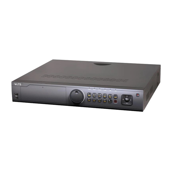
Page 15: Front Panel
User Manual of Network Video Recorder 1.1 Front Panel Figure 1. 1 Front Panel Table 1. 1 Description of Interfaces Name Function Description POWER Turns green when NVR is powered up. READY The LED is green when the device is running normally. The light is green when the IR remote control is enabled;... - Page 16 User Manual of Network Video Recorder Name Function Description Enter numeral “1”; 1/MENU Access the main menu interface. Enter numeral “2”; Enter letters “ABC”; The F1 button when used in a list field will select all items in the 2/ABC/F1 list.
-
Page 17: Ir Remote Control Operations
User Manual of Network Video Recorder Name Function Description Universal Serial Bus (USB) ports for additional devices such as USB USB Interfaces mouse and USB Hard Disk Drive (HDD). IR Receiver IR receiver interface 1.2 IR Remote Control Operations The NVR may also be controlled with the included IR remote control, shown in Figure 1. 2. Batteries (2×AAA) must be installed before operation. - Page 18 User Manual of Network Video Recorder Name Description REC Button Same as REC/SHOT button on front panel. PLAY Button Same as the PLAY/AUTO button on front panel. INFO Button Reserved. VOIP/MON Button Same as the MAIN/SPOT/ZOOM- button on front panel. MENU Button Same as the MENU/WIPER button on front panel.
-
Page 19: Usb Mouse Operation
User Manual of Network Video Recorder 1.3 USB Mouse Operation A regular 3-button (Left/Right/Scroll-wheel) USB mouse can also be used with this NVR. To use a USB mouse: 1. Plug USB mouse into one of the USB interfaces on the front panel of the NVR. 2. -
Page 20: Input Method Description
User Manual of Network Video Recorder 1.4 Input Method Description Figure 1. 3 Soft Keyboard (1) Figure 1. 4 Soft Keyboard (2) Description of the buttons on the soft keyboard: Table 1. 4 Description of the Soft Keyboard Icons Icons Description Icons Description... -
Page 21: Rear Panel
User Manual of Network Video Recorder 1.5 Rear Panel Figure 1. 5 LTN89XX Figure 1. 6 LTN89XX-P16 Table 1. 5 Description of Rear Panel Interfaces Item Description LAN Interface 2 network interfaces AUDIO OUT RCA connector for audio output. LINE IN RCA connector for audio input. -
Page 22: Chapter 2 Getting Started
User Manual of Network Video Recorder Chapter 2 Getting Started... -
Page 23: Starting Up And Shutting Down The Nvr
User Manual of Network Video Recorder 2.1 Starting Up and Shutting Down the NVR Purpose: Proper startup and shutdown procedures are crucial to expanding the life of the NVR. Before you start: Check that the voltage of the extra power supply is the same with the NVR’s requirement, and the ground connection is working properly. -
Page 24: Activating Your Device
User Manual of Network Video Recorder 2.2 Activating Your Device Purpose: For the first-time access, you need to activate the device by setting an admin password. No operation is allowed before activation. You can also activate the device via Web Browser, SADP or Client Software. Steps: 1. -
Page 25: Using The Wizard For Basic Configuration
User Manual of Network Video Recorder 2.3 Using the Wizard for Basic Configuration By default, the Setup Wizard starts once the NVR has loaded, as shown in Figure 2. 4. Figure 2. 4 Start Wizard Interface Operating the Setup Wizard: 1. - Page 26 User Manual of Network Video Recorder Figure 2. 6 Network Setting Two self-adaptive 10M/100M/1000M network interfaces provided for LTN89XX series, and two working modes are configurable: multi-address and network fault tolerance,. And 1 self-adaptive 10M/100M/1000M network interface for LTN89XX-P series. 4.
- Page 27 User Manual of Network Video Recorder Figure 2. 8 Advanced Network Parameters 6. Click Next button after you configured the network parameters, which takes you to the HDD Management window, shown in Figure 2. 9. Figure 2. 9 HDD Management 7.
- Page 28 User Manual of Network Video Recorder Figure 2. 10 Search for IP Cameras 10. Click Next button. Configure the recording for the added IP Cameras. Figure 2. 11 Record Settings 11. Click OK to complete the startup Setup Wizard.
-
Page 29: Login And Logout
User Manual of Network Video Recorder 2.4 Login and Logout 2.4.1 User Login Purpose: If NVR has logged out, you must login the device before operating the menu and other functions. Steps: 1. Select the User Name in the dropdown list. Figure 2. - Page 30 User Manual of Network Video Recorder Figure 2. 14 Logout 2. Click Logout. After you have logged out the system, menu operation on the screen is invalid. It is required to input a user name and password to unlock the system.
-
Page 31: Adding And Connecting The Ip Cameras
User Manual of Network Video Recorder 2.5 Adding and Connecting the IP Cameras 2.5.1 Activating the IP Camera Purpose: Before adding the camera, make sure the IP camera to be added is in active status. Steps: 1. Select the Add IP Camera option from the right-click menu in live view mode or click Menu> Camera> Camera to enter the IP camera management interface. -
Page 32: Adding The Online Ip Cameras
User Manual of Network Video Recorder Figure 2. 17 Set New Password Create New Password: If the admin password is not used, you must create the new password for the camera and confirm it. STRONG PASSWORD RECOMMENDED– We highly recommend you create a strong password of your own choosing (using a minimum of 8 characters, including upper case letters, lower case letters, numbers, and special characters) in order to increase the security of your product. - Page 33 User Manual of Network Video Recorder Figure 2. 18 Quick Adding IP Camera Interface 3. Select the detected IP camera and click the Add button to add it directly, and you can click the Search button to refresh the online IP camera manually. Or you can choose to custom add the IP camera by editing the parameters in the corresponding textfiled and then click the Add button to add it.
- Page 34 User Manual of Network Video Recorder Figure 2. 20 Selecting Multiple Channels OPTION 3: Steps: 1) On the IP Camera Management interface, click the Custom Adding button to pop up the Add IP Camera (Custom) interface. Figure 2. 21 Custom Adding IP Camera Interface 2) You can edit the IP address, protocol, management port, and other information of the IP camera to be added.
-
Page 35: Editing The Connected Ip Cameras And Configuring Customized Protocols
User Manual of Network Video Recorder Figure 2. 22 Successfully Added IP Cameras Table 2. 1 Explanation of the icons Icon Explanation Icon Explanation Edit basic parameters of the camera Add the detected IP camera. The camera is disconnected; you can click the icon to get the exception Delete the IP camera information of camera. - Page 36 User Manual of Network Video Recorder Figure 2. 23 Edit the Parameters Channel Port: If the connected device is an encoding device with multiple channels, you can choose the channel to connect by selecting the channel port No. in the dropdown list. 2.
- Page 37 User Manual of Network Video Recorder Figure 2. 25 Password Configuration of the Camera 3. Click OK to save the settings and exit the interface. Configuring the customized protocols Purpose: To connect the network cameras which are not configured with the standard protocols, you can configure the customized protocols for them.
-
Page 38: Editing Ip Cameras Connected To The Poe Interfaces
User Manual of Network Video Recorder Example: rtsp://192.168.1.55:554/ch1/main/av_stream. Protocol Name: Edit the name for the custom protocol. Enable Substream: If the network camera does not support sub-stream or the sub-stream is not needed leave the checkbox empty. Type: The network camera adopting custom protocol must support getting stream through standard RTSP. - Page 39 User Manual of Network Video Recorder 1. Enter the Camera Management interface. Menu> Camera> Camera Figure 2. 28 List of Connected Cameras The cameras connecting to the PoE interface cannot be deleted in this menu. 2. Click the button, and select the Adding Method in the drop-down list. •...
- Page 40 User Manual of Network Video Recorder Figure 2. 30 Edit IP Camera Interface - Manual...
-
Page 41: Chapter 3 Live View
User Manual of Network Video Recorder Chapter 3 Live View... -
Page 42: Introduction Of Live View
User Manual of Network Video Recorder 3.1 Introduction of Live View Live view shows you the video image getting from each camera in real time. The NVR automatically enters Live View mode when powered on. It is also at the very top of the menu hierarchy, thus pressing the ESC many times (depending on which menu you’re on) brings you to the Live View mode. -
Page 43: Operations In Live View Mode
User Manual of Network Video Recorder 3.2 Operations in Live View Mode In live view mode, there are many functions provided. The functions are listed below. • Single Screen: showing only one screen on the monitor. • Multi-screen: showing multiple screens on the monitor simultaneously. •... -
Page 44: Using An Auxiliary Monitor
User Manual of Network Video Recorder list. Multi-screen Adjust the screen layout by choosing from the dropdown list. Previous Screen Switch to the previous screen. Next Screen Switch to the next screen. Start/Stop Auto-switch Enable/disable the auto-switch of the screens. Start Recording Start continuous recording or motion detection recording of all channels. -
Page 45: Quick Setting Toolbar In Live View Mode
User Manual of Network Video Recorder 3.2.4 Quick Setting Toolbar in Live View Mode On the screen of each channel, there is a quick setting toolbar which shows when you single click the mouse in the corresponding screen. Figure 3. 2 Quick Setting Toolbar Table 3. - Page 46 User Manual of Network Video Recorder Figure 3. 4 Image Settings- Customize Live View Strategy can be selected to set strategy, including Real-time, Balanced, Fluency. Figure 3. 5 Live View Strategy Move the mouse onto the icon to show the real-time stream information, including the frame rate, bitrate, resolution and stream type.
-
Page 47: Adjusting Live View Settings
User Manual of Network Video Recorder 3.3 Adjusting Live View Settings Purpose: Live View settings can be customized according to different needs. You can configure the output interface, dwell time for screen to be shown, mute or turning on the audio, the screen number for each channel, etc. Steps: 1. - Page 48 User Manual of Network Video Recorder Figure 3. 8 Live View- Camera Order Select a View mode in , including 1/4/6/8/16/25/32/36/64-window division modes are supported depending on different models. Select the small window, and double-click on the channel number to display the channel on the window.
-
Page 49: Channel-Zero Encoding
User Manual of Network Video Recorder 3.4 Channel-zero Encoding Purpose: Sometimes you need to get a remote view of many channels in real time from web browser or CMS (Client Management System) software, in order to decrease the bandwidth requirement without affecting the image quality, channel-zero encoding is supported as an option for you. -
Page 50: Chapter 4 Ptz Controls
User Manual of Network Video Recorder Chapter 4 PTZ Controls... -
Page 51: Configuring Ptz Settings
User Manual of Network Video Recorder 4.1 Configuring PTZ Settings Purpose: Follow the procedure to set the parameters for PTZ. The configuring of the PTZ parameters should be done before you control the PTZ camera. Steps: 1. Enter the PTZ Settings interface. Menu >Camera>... -
Page 52: Setting Ptz Presets, Patrols & Patterns
User Manual of Network Video Recorder 4.2 Setting PTZ Presets, Patrols & Patterns Before you start: Please make sure that the presets, patrols and patterns should be supported by PTZ protocols. 4.2.1 Customizing Presets Purpose: Follow the steps to set the Preset location which you want the PTZ camera to point to when an event takes place. Steps: 1. -
Page 53: Customizing Patrols
User Manual of Network Video Recorder select the PTZ option in the right-click menu to show the PTZ control panel. 2. Choose Camera in the dropdown list. 3. Click the button to show the general settings of the PTZ control. Figure 4. -
Page 54: Calling Patrols
User Manual of Network Video Recorder Figure 4. 6 Key point Configuration 4. Configure key point parameters, such as the key point No., duration of staying for one key point and speed of patrol. The key point is corresponding to the preset. The Key Point No. determines the order at which the PTZ will follow while cycling through the patrol. -
Page 55: Customizing Patterns
User Manual of Network Video Recorder 4. You can click the Stop Patrol button to stop calling it. 4.2.5 Customizing Patterns Purpose: Patterns can be set by recording the movement of the PTZ. You can call the pattern to make the PTZ movement according to the predefined path. -
Page 56: Customizing Linear Scan Limit
User Manual of Network Video Recorder Figure 4. 9 PTZ Panel - General 3. Click the Call Pattern button to call it. 4. Click the Stop Pattern button to stop calling it. 4.2.7 Customizing Linear Scan Limit Purpose: The Linear Scan can be enabled to trigger the scan in the horizantal direction in the predefined range. This function is supported by some certain models. -
Page 57: Calling Linear Scan
User Manual of Network Video Recorder The speed dome starts linear scan from the left limit to the right limit, and you must set the left limit on the left side of the right limit, as well the angle from the left limit to the right limit should be no more than 180º. -
Page 58: Ptz Control Panel
User Manual of Network Video Recorder 1. Click the button PTZ in the lower-right corner of the PTZ setting interface; Or press the PTZ button on the front panel or click the PTZ Control icon in the quick setting bar to enter the PTZ setting menu in live view mode. - Page 59 User Manual of Network Video Recorder Figure 4. 13 PTZ Panel Table 4. 1 Description of the PTZ panel icons Icon Description Icon Description Icon Description Direction button and the auto-cycle Zoom+, Focus+, Iris+ Zoom-, Focus-, Iris- button The speed of the PTZ Light on/off Wiper on/off movement...
-
Page 60: Chapter 5 Recording Settings
User Manual of Network Video Recorder Chapter 5 Recording Settings... -
Page 61: Configuring Parameters
User Manual of Network Video Recorder 5.1 Configuring Parameters Purpose: By configuring the parameters you can define the parameters which affect the image quality, such as the transmission stream type, the resolution and so on. Before you start: 1. Make sure that the HDD has already been installed. If not, please install a HDD and initialize it. (Menu>HDD>General) Figure 5. - Page 62 User Manual of Network Video Recorder Figure 5. 3 Recording Parameters 2. Parameters Setting for Recording Select Record tab page to configure. You can configure the stream type, the resolution, and other parameters on your demand. Video Encode: select the video encoding to H.265 or H.264. ...
- Page 63 User Manual of Network Video Recorder • Post-record: The time you set to record after the event or the scheduled time. For example, when an alarm triggered the recording ends at 11:00, if you set the post-record time as 5 seconds, it records till 11:00:05.
-
Page 64: Configuring Recording And Capture Schedule
User Manual of Network Video Recorder 4. Parameters Settings for Capture Select the Capture tab. Figure 5. 6 Capture Parameters Configure the parameters. Click Apply to save the settings. The interval is the time period between two capturing actions. You can configure all the parameters on this menu on your demand. - Page 65 User Manual of Network Video Recorder Figure 5. 7 Record Schedule Different recording types are marked in different color icons. Continous: scheduled recording. Event: recording triggered by all event triggered alarm. Motion: recording triggered by motion detection. Alarm: recording triggered by alarm. M/A: recording triggered by either motion detection or alarm.
- Page 66 User Manual of Network Video Recorder Figure 5. 9 Edit Schedule III. To arrange other schedule, set the Start/End time for each period. Up to 8 periods can be configured for each day. And the time periods can’t be overlapped each other. IV.
-
Page 67: Configuring Motion Detection Recording And Capture
User Manual of Network Video Recorder Figure 5. 11 Draw the Schedule Click the Apply button to validate the settings. 3. (Optional) If the settings can also be used to other channels, click Copy, and then choose the channel to which you want to copy. - Page 68 User Manual of Network Video Recorder Figure 5. 13 Motion Detection 2. Configure Motion Detection: 1) Choose camera you want to configure. 2) Check the checkbox after Enable Motion Detection. 3) Drag and draw the area for motion detection by mouse. If you want to set the motion detection for all the area shot by the camera, click Full Screen.
-
Page 69: Configuring Alarm Triggered Recording And Capture
User Manual of Network Video Recorder 5) Select the channels which you want the motion detection event to trigger recording. 6) Click Apply to save the settings. 7) Click OK to back to the upper level menu. 8) Exit the Motion Detection menu. 3. -
Page 70: Manual Recording And Continuous Capture
User Manual of Network Video Recorder Click Settings. Figure 5. 18 Alarm Settings Choose the alarm triggered recording channel. Check the checkbox to select channel. Click Apply to save settings. Click OK to back to the upper level menu. Repeat the above steps to configure other alarm input parameters. If the settings can also be applied to other alarm inputs, click Copy and choose the alarm input number. -
Page 71: Configuring Holiday Recording And Capture
User Manual of Network Video Recorder continuous capture is prior to the scheduled recording and capture. Steps: 1. Enter the Manual settings interface. Menu> Manual Or press the REC/SHOT button on the front panel. Figure 5. 20 Manual Record 2. Enable the Manual Recording. Select Record on the left bar. - Page 72 User Manual of Network Video Recorder Steps: 1. Enter the Record setting interface. Menu > Record > Holiday Figure 5. 22 Holiday Settings 2. Enable Edit Holiday schedule. 1) Click to enter the Edit interface. Figure 5. 23 Edit Holiday Settings 2) Check the checkbox after Enable Holiday.
-
Page 73: Configuring Redundant Recording And Capture
User Manual of Network Video Recorder Configuring Recording and Capture Schedule. 5.7 Configuring Redundant Recording Capture Purpose: Enabling redundant recording and capture, which means saving the record files and captured pictures not only in the R/W HDD but also in the redundant HDD, will effectively enhance the data safety and reliability. . Steps: 1. -
Page 74: Configuring Hdd Group For Recording And Capture
User Manual of Network Video Recorder Menu> Record> Parameters Select Record tab. Click More Settings to enter the following interface. Figure 5. 26 Record Parameters Select Camera you want to configure in the drop-down list. Check the checkbox of Redundant Record/Capture. Click OK to save settings and back to the upper level menu. -
Page 75: Files Protection
User Manual of Network Video Recorder please refer to Chapter 14.4 Managing HDD Group. 3. Select General in the left side menu 4. Click to enter editing interface. 5. Configuring HDD group. 1) Choose a group number for the HDD group. 2) Click Apply and then in the pop-up message box, click Yes to save your settings. - Page 76 User Manual of Network Video Recorder Figure 5. 29 Normal Playback 3. During playback, click the button to lock the current recording file. In the multi-channel playback mde, clicking the button will lock all the record files related to the playback channels.
- Page 77 User Manual of Network Video Recorder 1. Enter Export setting interface. Menu> Export Figure 5. 31 Export 2. Select the channels you want to search by checking the checkbox to 3. Configure the record type, file type start/end time. 4. Click Search to show the results. Figure 5.
-
Page 78: Setting Hdd Property To Read-Only
User Manual of Network Video Recorder 5.9.2 Setting HDD Property to Read-only Steps: 1. Enter HDD setting interface. Menu> HDD Figure 5. 34 HDD General 2. Click to edit the HDD you want to protect. Figure 5. 35 HDD General- Editing To edit HDD property, you need to set the storage mode of the HDD to Group. -
Page 79: Chapter 6 Playback
User Manual of Network Video Recorder Chapter 6 Playback... -
Page 80: Playing Back Record Files
User Manual of Network Video Recorder 6.1 Playing Back Record Files 6.1.1 Instant Playback Purpose: Play back the recorded video files of a specific channel in the live view mode. Channel switch is supported. Instant playback by channel Steps: Choose a channel in live view mode and click the button in the quick setting toolbar. -
Page 81: Playback Interface
User Manual of Network Video Recorder Pressing numerical buttons will switch playback to the corresponding channels during playback process. Playback by Time Purpose: Play back video files recorded in specified time duration. Multi-channel simultaneous playback and channel switch are supported. Steps: 1. - Page 82 User Manual of Network Video Recorder Figure 6. 4 Playback Interface Click the channel(s) to execute simultaneous playback of multiple channels. Figure 6. 5 Toolbar of Playback indicates the start/end time of the record. Playback progress bar: use the mouse to click any point of the progress bar or drag the progress bar to locate specific frames.
-
Page 83: Playing Back By Event Search
User Manual of Network Video Recorder Button Operation Button Operation Button Operation Button Operation Video type Playback type / Full screen Exit picture The playing speed of 256X is supported. 6.1.3 Playing Back by Event Search Purpose: Play back record files on one or several channels searched out by event type (e.g., alarm input, motion detection and VCA). -
Page 84: Playing Back By Tag
User Manual of Network Video Recorder 7. Click button to play back the file. Pre-play and post-play can be configured. 8. Playback interface. The toolbar in the bottom part of Playback interface can be used to control playing process. Figure 6. 7 Interface of Playback by Event You can click button to select the previous or next event. - Page 85 User Manual of Network Video Recorder Figure 6. 8 Interface of Playback by Time Click button to add default tag. Click button to add customized tag and input tag name. Max. 64 tags can be added to a single video file. 3.
-
Page 86: Playing Back By Smart Playback
User Manual of Network Video Recorder Figure 6. 10 Interface of Playback by Tag Pre-play and post-play can be configured. You can click button to select the previous or next tag. Please refer to Table 6.1 for the description of buttons on the toolbar. - Page 87 User Manual of Network Video Recorder Menu>Playback 2. Select the Smart in the drop-down list on the top-left side. 3. Select a camera in the camera list. 4. Select a date in the calendar and click the button on the left toolbar to play the video file. Figure 6.
-
Page 88: Playing Back By System Logs
User Manual of Network Video Recorder 6. You can click to configure the smart settings. Figure 6. 13 Smart Settings Skip the Non-Related Video: The non-related video will not be played if this function is enabled. Play Non-Related Video at: Set the speed to play the non-related video. Max./8/4/1 are selectable. Play Related Video at: Set the speed to play the related video. - Page 89 User Manual of Network Video Recorder Figure 6. 15 System Log Search Interface 3. Choose a log with record file and click button to enter Playback interface. If there is no record file at the time point of the log, the message box “No result found” will pop up. Figure 6.
-
Page 90: Playing Back External File
User Manual of Network Video Recorder 6.1.7 Playing Back External File Purpose: Perform the following steps to look up and play back files in the external devices. Steps: 1. Enter Tag Search interface. Menu>Playback 2. Select the External File in the drop-down list on the top-left side. The files are listed in the right-side list. -
Page 91: Playing Back Pictures
User Manual of Network Video Recorder Figure 6. 19 Interface of Sub-periods Playback According to the defined number of split-screens, the video files on the selected date can be divided into average segments for playback. E.g., if there are video files existing between 16:00 and 22:00, and the 6-screen display mode is selected, then it can play the video files for 1 hour on each screen simultaneously. -
Page 92: Auxiliary Functions Of Playback
User Manual of Network Video Recorder Figure 6. 20 Result of Picture Playback 6. The toolbar in the bottom part of Playback interface can be used to control playing process. Figure 6. 21 Picture Playback Toolbar Table 1. 1 Detailed Explanation of Picture-playback Toolbar Button Function Button... -
Page 93: Digital Zoom
User Manual of Network Video Recorder • Using the Front Panel: Click the button to set the speed to Single frame. One click on button, one click on the playback screen or Enter button on the front panel represents playback or reverse playback of one frame. 6.2.2 Digital Zoom Steps: 1. -
Page 94: Reverse Playback Of Multi-Channel
User Manual of Network Video Recorder Figure 6. 23 File Management 3. You can view the saved video clips, captured playback pictures, lock/unlock the files and edit the tags which you added in the playback mode. 4. If required, select the items and click Export All or Export to export the clips/pictures/files/tags to local storage device. - Page 95 User Manual of Network Video Recorder The record files will be marked by two lines on the process bar. The upper one indicates the record files of the selected channel; and the lower one indicates the record files of all the selected channels. 3.
-
Page 96: Chapter 7 Backup
User Manual of Network Video Recorder Chapter 7 Backup... -
Page 97: Backing Up Record Files
User Manual of Network Video Recorder 7.1 Backing up Record Files 7.1.1 Quick Export Purpose: Export record files to backup device(s) quickly. Steps: 1. Enter Video Export interface. Menu>Export>Normal Choose the channel(s) you want to back up and click Quick Export button. The time duration of record files on a specified channel cannot exceed one day. - Page 98 User Manual of Network Video Recorder Figure 7. 2 Quick Export using USB1-1 Stay in the Exporting interface until all record files are exported. Figure 7. 3 Export Finished 4. Check backup result. Choose the record file in Export interface and click button to check it.
-
Page 99: Backing Up By Normal Video/Picture Search
User Manual of Network Video Recorder Figure 7. 4 Checkup of Quick Export Result Using USB1-1 7.1.2 Backing up by Normal Video/Picture Search Purpose: The record files can be backup to various devices, such as USB devices (USB flash drives, USB HDDs, USB writer), SATA writer Backup using USB flash drives and USB HDDs Steps:... - Page 100 User Manual of Network Video Recorder The size of the currently selected files is displayed in the lower-left corner of the window. Figure 7. 6 Result of Normal Video Search for Backup 5. Export the video files or picture files. Click Export All button to export all the files.
-
Page 101: Backing Up By Event Search
User Manual of Network Video Recorder Figure 7. 8 Export Finished The backup of video files using USB writer or SATA writer has the same operating instructions. Please refer to steps described above. 7.1.3 Backing up by Event Search Purpose: Back up event-related record files using USB devices (USB flash drives, USB HDDs, USB writer), SATA writer or eSATA HDD. -
Page 102: Backing Up Video Clips Or Captured Playback Pictures
User Manual of Network Video Recorder Figure 7. 10 Result of Event Search 6. Export the video files. Please refer to step5 of Chapter 7.1.2 Backing up by Normal Video Search for details. 7.1.4 Backing up Video Clips or Captured Playback Pictures Purpose: You may also select video clips or captured pictures in playback mode to export directly during Playback, using USB devices (USB flash drives, USB HDDs, USB writer), SATA writer or eSATA HDD. -
Page 103: Managing Backup Devices
User Manual of Network Video Recorder 7.2 Managing Backup Devices Management of USB flash drives, USB HDDs and eSATA HDDs Steps: 1. Enter the Export interface. Figure 7. 12 Storage Device Management 2. Backup device management. Click New Folder button if you want to create a new folder in the backup device. Select a record file or folder in the backup device and click button if you want to delete it. -
Page 104: Setting Hot Spare Device
User Manual of Network Video Recorder each working device. Add a hot spare Add the normal Set a hot spare Start device on normal device on the hot Finish device device spare device Figure 7. 13 Building Hot Spare System 7.3.1 Setting Hot Spare Device ... -
Page 105: Managing Hot Spare System
User Manual of Network Video Recorder Figure 7. 15 Setting Working Mode for Working device 5. Click the Apply button to save the settings. 7.3.3 Managing Hot Spare System Steps: 1. Enter the Hot Spare Settings interface of the hot spare device. Menu >... - Page 106 User Manual of Network Video Recorder Figure 7. 17 No Recording When the working device gets offline, the hot spare device will record the video of the IP Camera connected to the working device for backup, and the working status of the hot spare device is displayed as Backing up. The record backing up can be functioned for 1 working device at a time.
-
Page 107: Chapter 8 Alarm Settings
User Manual of Network Video Recorder Chapter 8 Alarm Settings... -
Page 108: Setting Motion Detection Alarm
User Manual of Network Video Recorder 8.1 Setting Motion Detection Alarm Steps: 1. Enter Motion Detection interface of Camera Management and choose a camera you want to set up motion detection. Menu> Camera> Motion Figure 8. 1 Motion Detection Setup Interface 2. -
Page 109: Setting Sensor Alarms
User Manual of Network Video Recorder Figure 8. 3 Set Arming Schedule of Motion Detection 5. Click Handling tab to set up alarm response actions of motion alarm (please refer to Chapter Setting Alarm Response Actions). 6. If you want to set motion detection for another channel, repeat the above steps or just click Copy in the Motion Detection interface to copy the above settings to it. - Page 110 User Manual of Network Video Recorder Figure 8. 4 Alarm Status Interface of System Configuration 2. Set up the handling action of the selected alarm input. Check the Enable checkbox and click Settings button to set up its alarm response actions. Figure 8.
-
Page 111: Detecting Video Loss Alarm
User Manual of Network Video Recorder patterns are exclusive. Figure 8. 7 Set PTZ Linking of Alarm Input 7. If you want to set handling action of another alarm input, repeat the above steps. Or you can click the Copy button on the Alarm Input Setup interface and check the checkbox of alarm inputs to copy the settings to them. - Page 112 User Manual of Network Video Recorder Figure 8. 9 Video Loss Setup Interface 2. Set up handling action of video loss. Check the checkbox of “Enable Video Loss Alarm”, and click button to set up handling action of video loss. 3.
-
Page 113: Detecting Video Tampering Alarm
User Manual of Network Video Recorder 8.4 Detecting Video Tampering Alarm Purpose: Trigger alarm when the lens is covered and take alarm response action(s). Steps: 1. Enter Video Tampering interface of Camera Management and select a channel you want to detect video tampering. -
Page 114: Handling Exceptions Alarm
User Manual of Network Video Recorder Figure 8. 12 Set Arming Schedule of Video Tampering 4. Select Linkage Action tab to set up alarm response actions of video tampering alarm (please refer to Chapter Setting Alarm Response Actions). 5. Click the OK button to complete the video tampering settings of the channel. 8.5 Handling Exceptions Alarm Purpose: Exception settings refer to the handling action of various exceptions, e.g. -
Page 115: Setting Alarm Response Actions
User Manual of Network Video Recorder 8.6 Setting Alarm Response Actions Purpose: Alarm response actions will be activated when an alarm or exception occurs, including Event Hint Display, Full Screen Monitoring, Audible Warning (buzzer), Notify Surveillance Center, Trigger Alarm Output and Send Email. Event Hint Display When an event or exception happens, a hint can be displayed on the lower-left corner of live view image. - Page 116 User Manual of Network Video Recorder Auto-switch will terminate once the alarm stops and you will be taken back to the Live View interface. You must select during “Trigger Channel” settings the channel(s) you want to make full screen monitoring. Audible Warning Trigger an audible beep when an alarm is detected.
-
Page 117: Triggering Or Clearing Alarm Output Manually
User Manual of Network Video Recorder Figure 8. 17 Set Arming Schedule of Alarm Output 3. Repeat the above steps to set up arming schedule of other days of a week. You can also use Copy button to copy an arming schedule to other days. Click the OK button to complete the video tampering settings of the alarm output No. - Page 118 User Manual of Network Video Recorder Click Trigger All button if you want to trigger all alarm outputs. Click Clear All button if you want to clear all alarm output. Figure 8. 19 Clear or Trigger Alarm Output Manually...
-
Page 119: Chapter 9 Vca Alarm
User Manual of Network Video Recorder Chapter 9 VCA Alarm... -
Page 120: Line Crossing Detection
User Manual of Network Video Recorder The NVR supports the VCA detection alarm (face detection, vehicle detection, line crossing detection and intrusion detection, region entrance detection, region exiting detection, loitering detection, people gathering detection, fast moving detection, parking detection, unattended baggage detection, object removal detection, audio loss exception detection, sudden change of sound intensity detection, and defocus detection) sent by IP camera. -
Page 121: Intrusion Detection
User Manual of Network Video Recorder Figure 9. 1 Set Line Crossing Detection Rules Click and set two points in the preview window to draw a virtual line. You can use the to clear the existing virtual line and re-draw it. Up to 4 rules can be configured. - Page 122 User Manual of Network Video Recorder Menu> Camera> VCA Select the camera to configure the VCA. You can click the checkbox of Save VCA Picture to save the captured pictures of VCA detection. Select the VCA detection type to Intrusion Detection. Check the Enable checkbox to enable this function.
-
Page 123: People Gathering Detection
User Manual of Network Video Recorder Figure 9. 4 Draw Area for Intrusion Detection Click Apply to save the settings. 9.3 People Gathering Detection Purpose: People gathering detection alarm is triggered when people gather around in a pre-defined virtual region, and a series of actions can be taken when the alarm is triggered. -
Page 124: Chapter 10 Vca Search
User Manual of Network Video Recorder Chapter 10 VCA Search... -
Page 125: People Counting
User Manual of Network Video Recorder With the configured VCA detection, the NVR supports the VCA search for the behavior analysis, face capture, people counting and heat map results. 10.1 People Counting Purpose: The People Counting is used to calculate the number of people entered or left a certain configured area and form in daily/weekly/monthly/annual reports for analysis. -
Page 126: Chapter 11 Network Settings
User Manual of Network Video Recorder Chapter 11 Network Settings... -
Page 127: Configuring General Settings
User Manual of Network Video Recorder 11.1 Configuring General Settings Purpose: Network settings must be properly configured before you operate NVR over network. Steps: 1. Enter the Network Settings interface. Menu >Configuration>Network 2. Select the General tab. Figure 11. 1 Network Settings Interface 3. -
Page 128: Configuring Advanced Settings
User Manual of Network Video Recorder Figure 11. 2 Net Fault-tolerance Working Mode 11.2 Configuring Advanced Settings 11.2.1 Configuring PPPoE Settings Purpose: Your NVR also allows access by Point-to-Point Protocol over Ethernet (PPPoE). Steps: 1. Enter the Network Settings interface. Menu >Configuration>... -
Page 129: Configuring Pt Cloud
User Manual of Network Video Recorder 11.2.2 Configuring PT Cloud Purpose: PT Cloud provides the mobile phone application and as well the service platform page to access and manage your connected NVR, which enables you to get a convenient remote access to the surveillance system. Steps: 1. - Page 130 2) Enter the Device Domain Name. You can use the alias you registered in the LTS server or define a new device domain name. If a new alias of the device domain name is defined in the NVR, it will replace the old one registered on the server.
- Page 131 User Manual of Network Video Recorder Figure 11. 8 PeanutHull Settings Interface • NO-IP: Enter the account information in the corresponding fields. Refer to the DynDNS settings. 1) Enter Server Address for NO-IP. 2) In the Device Domain Name text field, enter the domain obtained from the NO-IP website (www.no-ip.com).
- Page 132 User Manual of Network Video Recorder Figure 11. 10 HiDDNS Settings Interface Register the device on the HiDDNS server. 1) Go to the HiDDNS website: www.hiddns.com. Figure 11. 11 Register an Account 2) Click to register an account if you do not have one and use the account to log in.
- Page 133 User Manual of Network Video Recorder Figure 11. 12 Register an Account 3) In the Device Management interface, click to register the device. Figure 11. 13 Register the Device 4) Input Device Serial No., Device Domain (Device Name) and HTTP Port. And click OK to add the device.
-
Page 134: Configuring Ntp Server
User Manual of Network Video Recorder enter http:// www.hiddns.com/alias:HTTP port in the address bar to access the device. You can refer to Chapter 9.2.11 for the mapped HTTP port No. OPTION 2: Access the devices via NVMS7000 For NVMS7000, in the Add Device window, select and then edit the device information. -
Page 135: Configuring Snmp
User Manual of Network Video Recorder • NTP Server: IP address of NTP server. • NTP Port: Port of NTP server. 5. Click the Apply button to save and exit the interface. The time synchronization interval can be set from1 to 10080min, and the default value is 60min. If the NVR is connected to a public network, you should use a NTP server that has a time synchronization function, such as the server at the National Time Center (IP Address: 210.72.145.44). -
Page 136: Configuring Https Port
User Manual of Network Video Recorder Figure 11. 17 More Settings Interface Configure the remote alarm host, server port, HTTP port, multicast, RTSP port. Alarm Host IP/Port: With a remote alarm host configured, the device will send the alarm event or exception message to the host when an alarm is triggered. - Page 137 User Manual of Network Video Recorder Example: If you set the port number as 443 and the IP address is 192.0.0.64, you may access the device by inputting https://192.0.0.64:443 via the web browser. The HTTPS port can be only configured through the web browser. Steps: 1.
-
Page 138: Configuring Email
User Manual of Network Video Recorder 2) Download the certificate request and submit it to the trusted certificate authority for signature. 3) After receiving the signed valid certificate, import the certificate to the device. 5. There will be the certificate information after you successfully create and install the certificate. Figure 11. -
Page 139: Configuring Nat
User Manual of Network Video Recorder Figure 11. 23 Email Settings Interface 5. Configure the following Email settings: Enable Server Authentication (optional): Check the checkbox to enable the server authentication feature. User Name: The user name of sender’s account registered on the SMTP server. Password: The password of sender’s account registered on the SMTP server. - Page 140 User Manual of Network Video Recorder which your device is connected. When the network working mode of the device is set as multi-address, the Default Route of the device should be in the same network segment as that of the LAN IP address of the router. Steps: 1.
- Page 141 User Manual of Network Video Recorder The value of the RTSP port No. should be 554 or between 1024 and 65535, while the value of the other ports should be between 1 and 65535 and the value must be different from each other.
-
Page 142: Configuring High-Speed Download
User Manual of Network Video Recorder Figure 11. 28 External Port Settings Dialog Box 5. Click OK to save the setting for the current port and return to the upper-level menu. 6. Click Apply button to save the settings. 7. Enter the virtual server setting page of router; fill in the blank of Internal Source Port with the internal port value, the blank of External Source Port with the external port value, and other required contents. -
Page 143: Configuring Virtual Host
User Manual of Network Video Recorder 3. Check the checkbox of Enable High-speed Download. And click the OK button in the pop-up message box to confirm the settings. Figure 11. 30 High-speed Download Settings Menu Figure 11. 31 Message Box of High-speed Download 4. -
Page 144: Checking Network Traffic
User Manual of Network Video Recorder Figure 11. 33 Connect to IP Camera 5. Click the link and the page of IP camera management appears. 11.3 Checking Network Traffic Purpose: You can check the network traffic to obtain real-time information of NVR such as linking status, MTU, sending/receiving rate, etc. -
Page 145: Configuring Network Detection
User Manual of Network Video Recorder 11.4 Configuring Network Detection Purpose: You can obtain network connecting status of NVR through the network detection function, including network delay, packet loss, etc. 11.4.1 Testing Network Delay and Packet Loss Steps: 1. Enter the Network Traffic interface. Menu >Maintenance>Net Detect 2. -
Page 146: Checking The Network Status
User Manual of Network Video Recorder Click Refresh button if the connected local backup device cannot be displayed. When it fails to detect the backup device, please check whether it is compatible with the NVR. You can format the backup device if the format is incorrect. -
Page 147: Checking Network Statistics
User Manual of Network Video Recorder Figure 11. 39 Network Status Checking If the network is normal the following message box pops out. Figure 11. 40 Network Status Checking Result If the message box pops out with other information instead of this one, you can click Network button to show the quick setting interface of the network parameters. - Page 148 User Manual of Network Video Recorder 3. Check the bandwidth of IP Camera, bandwidth of Remote Live View, bandwidth of Remote Playback, bandwidth of Net Receive Idle and bandwidth of Net Send Idle. 4. You can click Refresh to get the newest status.
-
Page 149: Chapter 12 Hdd Management
User Manual of Network Video Recorder Chapter 12 HDD Management... -
Page 150: Initializing Hdds
User Manual of Network Video Recorder 12.1 Initializing HDDs Purpose: A newly installed hard disk drive (HDD) must be initialized before it can be used with your NVR. A message box pops up when the NVR starts up if there exits any uninitialized HDD. Figure 12. -
Page 151: Managing Network Hdd
User Manual of Network Video Recorder Figure 12. 5 HDD Status Changes to Normal Initializing the HDD will erase all data on it. 12.2 Managing Network HDD Purpose: You can add the allocated NAS or disk of IP SAN to NVR, and use it as network HDD. Up to 8 network disks can be added. - Page 152 User Manual of Network Video Recorder 4) Click the OK button to add the configured NAS disk. Figure 12. 8 Add NAS Disk • Add IP SAN: 1) Enter the NetHDD IP address in the text field. 2) Click the Search button to search the available IP SAN disks. 3) Select the IP SAN disk from the list shown below.
-
Page 153: Managing Esata
User Manual of Network Video Recorder Figure 12. 10 Initialize Added NetHDD 12.3 Managing eSATA Purpose: When there is an external eSATA device connected to NVR, you can configure eSATA for the use of Record/Capture or Export, and you can manage the eSATA in the NVR. Steps: Enter the Advanced Record Settings interface. -
Page 154: Managing Hdd Group
User Manual of Network Video Recorder Figure 12. 12 Initialize Added eSATA 12.4 Managing HDD Group 12.4.1 Setting HDD Groups Purpose: Multiple HDDs can be managed in groups. Video from specified channels can be recorded onto a particular HDD group through HDD settings. Steps: 1. -
Page 155: Setting Hdd Property
User Manual of Network Video Recorder Figure 12. 15 Local HDD Settings Interface 7. Select the Group number for the current HDD. The default group No. for each HDD is 1. 8. Click the OK button to confirm the settings. Figure 12. -
Page 156: Configuring Quota Mode
User Manual of Network Video Recorder Figure 12. 17 Set HDD Property 3. Set the HDD property to R/W, Read-only or Redundancy. 4. Click the OK button to save the settings and exit the interface. 5. In the HDD Information menu, the HDD property will be displayed in the list. At least 2 hard disks must be installed on your NVR when you want to set a HDD to Redundancy, and there is one HDD with R/W property. -
Page 157: Configuring Disk Clone
User Manual of Network Video Recorder Figure 12. 19 Configure Record/Picture Quota 5. You can copy the quota settings of the current camera to other cameras if required. Click the Copy button to enter the Copy Camera menu, as shown in Figure 12. 20. Figure 12. - Page 158 User Manual of Network Video Recorder 1. Enter the HDD Advanced Setting interface: Menu > HDD > Advanced 2. Click the Disk Clone tab to enter the disk clone configuring interface. Figure 12. 21 Disk Clone Configuration Interface 3. Make sure the usage of the eSATA disk is set as Export. If not, click the Set button to set it.
-
Page 159: Checking Hdd Status
User Manual of Network Video Recorder 12.7 Checking HDD Status Purpose: You may check the status of the installed HDDs on NVR so as to take immediate check and maintenance in case of HDD failure. Checking HDD Status in HDD Information Interface Steps: 1. -
Page 160: Hdd Detection
User Manual of Network Video Recorder Figure 12. 26 View HDD Status (2) 12.8 HDD Detection Purpose: The device provides the HDD detection function such as the adopting of the S.M.A.R.T. and the Bad Sector Detection technique. The S.M.A.R.T. (Self-Monitoring, Analysis and Reporting Technology) is a monitoring system for HDD to detect and report on various indicators of reliability in the hopes of anticipating failures. - Page 161 User Manual of Network Video Recorder Figure 12. 27 S.M.A.R.T Settings Interface The related information of the S.M.A.R.T. is shown on the interface. You can choose the self-test types as Short Test, Expanded Test or the Conveyance Test. Click the start button to start the S.M.A.R.T. HDD self-evaluation. If you want to use the HDD even when the S.M.A.R.T.
-
Page 162: Configuring Hdd Error Alarms
User Manual of Network Video Recorder Figure 12. 28 Bad Sector Detection And you can click Error info button to see the detailed damage information. And you can also pause/resume or cancel the detection. 12.9 Configuring HDD Error Alarms Purpose: You can configure the HDD error alarms when the HDD status is Uninitialized or Abnormal. - Page 163 User Manual of Network Video Recorder Figure 12. 29 Configure HDD Error Alarm 4. When the Trigger Alarm Output is selected, you can also select the alarm output to be triggered from the list below. 5. Click the Apply button to save the settings...
-
Page 164: Chapter 13 Camera Settings
User Manual of Network Video Recorder Chapter 13 Camera Settings... -
Page 165: Configuring Osd Settings
User Manual of Network Video Recorder 13.1 Configuring OSD Settings Purpose: You can configure the OSD (On-screen Display) settings for the camera, including date /time, camera name, etc. Steps: 1. Enter the OSD Configuration interface. Menu > Camera > OSD 2. -
Page 166: Configuring Privacy Mask
User Manual of Network Video Recorder 13.2 Configuring Privacy Mask Purpose: You are allowed to configure the four-sided privacy mask zones that cannot be viewed by the operator. The privacy mask can prevent certain surveillance areas to be viewed or recorded. Steps: 1. -
Page 167: Configuring Video Parameters
User Manual of Network Video Recorder 13.3 Configuring Video Parameters Steps: 1. Enter the Image Settings interface. Menu > Camera >Image Figure 13. 4 Image Settings Interface 2. Select the camera to set image parameters. 3. You can click on the arrow to change the value of each parameter. 4. -
Page 168: Chapter 14 Nvr Management And Maintenance
User Manual of Network Video Recorder Chapter 14 Management Maintenance... -
Page 169: Viewing System Information
User Manual of Network Video Recorder 14.1 Viewing System Information Steps: 1. Enter the System Information interface. Menu >Maintenance>System Info 2. You can click the Device Info, Camera, Record, Alarm, Network and HDD tabs to view the system information of the device. Figure 14. - Page 170 User Manual of Network Video Recorder Minor Type. 3. Click the Search button to start search log files. 4. The matched log files will be displayed on the list shown below. Figure 14. 3 Log Search Results Up to 2000 log files can be displayed each time. 5.
-
Page 171: Importing/Exporting Ip Camera Info
User Manual of Network Video Recorder Figure 14. 5 Export Log Files 7. Select the backup device from the dropdown list of Device Name. 8. Select the format of the log files to be exported. Up to 9 formats are selectable. 9. -
Page 172: Upgrading System
User Manual of Network Video Recorder 1. Enter the Import/Export Configuration File interface. Menu > Maintenance >Import/Export Figure 14. 6 Import/Export Config File 2. Click the Export button to export configuration files to the selected local backup device. 3. To import a configuration file, select the file from the selected backup device and click the Import button. After the import process is completed, you must reboot the NVR. -
Page 173: Upgrading By Ftp
User Manual of Network Video Recorder Figure 14. 7 Local Upgrade Interface 4. Select the update file from the backup device. 5. Click the Upgrade button to start upgrading. 6. After the upgrading is complete, reboot the NVR to activate the new firmware. 14.5.2 Upgrading by FTP Before you start: Ensure the network connection of the PC (running FTP server) and the device is valid and correct. - Page 174 User Manual of Network Video Recorder Figure 14. 9 Restore Defaults 2. Select the restoring type from the following three options. Restore Defaults: Restore all parameters, except the network (including IP address, subnet mask, gateway, MTU, NIC working mode, default route, server port, etc.) and user account parameters, to the factory default settings. Factory Defaults: Restore all parameters to the factory default settings.
-
Page 175: Chapter 15 Others
User Manual of Network Video Recorder Chapter 15 Others... -
Page 176: Configuring General Settings
User Manual of Network Video Recorder 15.1 Configuring General Settings Purpose: You can configure the BNC output standard, VGA output resolution, mouse pointer speed through the Menu > Configuration > General interface. Steps: 1. Enter the General Settings interface. Menu >Configuration> General 2. -
Page 177: Configuring More Settings
User Manual of Network Video Recorder Figure 15. 2 DST Settings Interface You can check the checkbox before the Auto DST Adjustment item. Or you can manually check the Enable DST checkbox, and then you choose the date of the DST period. 15.3 Configuring More Settings Steps: 1. -
Page 178: Adding A User
User Manual of Network Video Recorder 15.4.1 Adding a User Steps: 1. Enter the User Management interface. Menu >Configuration>User Figure 15. 4 User Management Interface 2. Click the Add button to enter the Add User interface. Figure 15. 5 Add User Menu 3. - Page 179 User Manual of Network Video Recorder • Guest: The Guest user has no permission of Two-way Audio in Remote Configuration and only has the local/remote playback in the Camera Configuration by default. User’s MAC Address: The MAC address of the remote PC which logs onto the NVR. If it is configured and enabled, it only allows the remote user with this MAC address to access the NVR.
-
Page 180: Deleting A User
User Manual of Network Video Recorder and importing/exporting configuration files. • Remote Camera Management: Remote adding, deleting and editing of the IP cameras. • Remote Serial Port Control: Configuring settings for RS-232 and RS-485 ports. • Remote Video Output Control: Sending remote button control signal. •... -
Page 181: Editing A User
User Manual of Network Video Recorder 15.4.3 Editing a User For the added user accounts, you can edit the parameters. Steps: 1. Enter the User Management interface. Menu >Configuration>User 2. Select the user to be edited from the list, as shown in Figure 15. 8. 3. -
Page 182: Chapter 16 Appendix
User Manual of Network Video Recorder Chapter 16 Appendix... -
Page 183: Specifications
User Manual of Network Video Recorder 16.1 Specifications LTN8916/LTN8932 Model LTN8916 LTN8932 16-ch 32-ch IP video input Video/Audio Up to 12 MP resolution input Two-way audio 1-ch, RCA (2.0 Vp-p, 1kΩ) Incoming bandwidth 160 Mbps 320 Mbps Network Outgoing bandwidth... - Page 184 User Manual of Network Video Recorder LTN8916-P16/LTN8932-P16 Model LTN8916-P16 LTN8932-P16 16-ch 32-ch IP video input Video/Audio Up to 12 MP resolution input Two-way audio 1-ch, RCA (2.0 Vp-p, 1kΩ) Incoming bandwidth 160 Mbps 320 Mbps Network Outgoing bandwidth 160 Mbps...
-
Page 185: Glossary
User Manual of Network Video Recorder 16.2 Glossary • Dual Stream: Dual stream is a technology used to record high resolution video locally while transmitting a lower resolution stream over the network. The two streams are generated by the DVR, with the main stream having a maximum resolution of 4CIF and the sub-stream having a maximum resolution of CIF. -
Page 186: Troubleshooting
User Manual of Network Video Recorder 16.3 Troubleshooting No image displayed on the monitor after starting up normally. Possible Reasons No VGA or HDMI connections. Connection cable is damaged. c) Input mode of the monitor is incorrect. Steps 1. Verify the device is connected with the monitor via HDMI or VGA cable. If not, please connect the device with the monitor and reboot. - Page 187 User Manual of Network Video Recorder The status of the added IP camera displays as “Disconnected” when it is connected through Private Protocol. Select “Menu>Camera>Camera>IP Camera” to get the camera status. Possible Reasons Network failure, and the NVR and IP camera lost connections. The configured parameters are incorrect when adding the IP camera.
- Page 188 User Manual of Network Video Recorder Simultaneously press Ctrl and C to exit the ping command. Example: Input ping 172.6.22.131 –l 1472 –f. 4. Verify the switch is not flow control. Check the brand, model of the switch connecting IP camera and NVR, and contact with the manufacturer of the switch to check if it has the function of flow control.
- Page 189 User Manual of Network Video Recorder 3. Check if the fault is solved by the above steps. If it is solved, finish the process. If not, please contact the engineer from our company to do the further process. Live view stuck when video output remotely via the Internet Explorer or platform software. Possible Reasons: a) Poor network between NVR and IP camera, and there exists packet loss during the transmission.
- Page 190 User Manual of Network Video Recorder If the resource is not enough, please end some unnecessary processes. 4. Check if the fault is solved by the above steps. If it is solved, finish the process. If not, please contact the engineer from our company to do the further process. ...
- Page 191 User Manual of Network Video Recorder 5. Check if the fault is solved by the above steps. If it is solved, finish the process. If not, please contact the engineer from our company to do the further process. No record file found in the NVR local HDD, and prompt “No record file found”. Possible Reasons: a) The time setting of system is incorrect.
-
Page 192: List Of Compatible Ip Cameras
User Manual of Network Video Recorder 16.4 List of Compatible IP Cameras For the list, our company holds right to interpret. ONVIF compatibility refers to the camera can be supported both when it uses the ONVIF protocol and its private protocols. - Page 193 User Manual of Network Video Recorder IP Camera Manufacturer Max. Model Version Sub-stream Audio or Protocol Resolution 1920*1080 VB-H410(ONVIF compatibility) Ver.+1.0.0 × √ (1280*960) VB-S9000F Ver. 1.0.0 1920*1080 × × VB-S300D Ver. 1.0.0 1920*1080 × × Canon VB-H6100D Ver. 1.0.0 1920*1080 ×...
- Page 194 User Manual of Network Video Recorder IP Camera Manufacturer Max. Model Version Sub-stream Audio or Protocol Resolution F3106 (ONVIF compatibility) M2.1.6.03P8 1280*1024 √ (×) √ F3110 (ONVIF compatibility) M2.1.6.01 1280*720 √ (×) √ F3206 (ONVIF compatibility) MG.1.6.02c045 1920*1080 √ (×) √...
- Page 195 User Manual of Network Video Recorder IP Camera Manufacturer Max. Model Version Sub-stream Audio or Protocol Resolution DS-2CD4212FWD-I V5.3.0 build150327 1280*960 √ × DS-2CD4212FWD-IS V5.3.0 build150327 1280*960 √ √ DS-2CD4224F-I V5.3.0 build150327 1920*1080 √ × DS-2CD4232FWD-I V5.3.0 build150327 2048*1536 √ ×...
- Page 196 User Manual of Network Video Recorder IP Camera Manufacturer Max. Model Version Sub-stream Audio or Protocol Resolution DS-2CD864FWD-E V5.2.0 build 140721 1280*720 √ √ DS-2CD876MF/BF-E V4.0.3 build120913 1600*1200 √ √ DS-2CD877BF V4.0.3 build120913 1920*1080 √ √ DS-2CD886MF-E V4.0.3 build 120913 2560*1920 √...
- Page 197 User Manual of Network Video Recorder IP Camera Manufacturer Max. Model Version Sub-stream Audio or Protocol Resolution iDS-2CD9151A V3.8.2 build141121 2448*2048 √ × iDS-2CD9152-EH V3.8.2 build141121 2592*2048 √ × iDS-2CD9152-H V3.8.2 build141121 2592*2048 √ × DS-2CD9120-H V3.7.1 build140417 1600*1200 √ ×...
- Page 198 User Manual of Network Video Recorder IP Camera Manufacturer Max. Model Version Sub-stream Audio or Protocol Resolution DS-6602HCI V1.2.1 build131202 352*288 √ √ DS-6604HCI V1.2.1 build131202 352*288 √ √ DS-6601HFI(-SATA) V1.2.1 build131202 704*576 √ √ DS-6602HFI(SATA) V1.2.1 build131202 704*576 √ √...
- Page 199 User Manual of Network Video Recorder IP Camera Manufacturer Max. Model Version Sub-stream Audio or Protocol Resolution iDS-2DF7276-AH/DH/AFH V5.2.8 build150124 1280*960 √ √ DS-2DF5276-AH/DH/A3H/D3H/AFH/A3FH V5.2.8 build150124 1280*960 √ √ iDS-2DF5276-AH/DH/A3H/D3H/AFH/A3FH V5.2.8 build150124 1280*960 √ √ DS_2DF7130I5-AW V5.2.8 build150124 1280*960 √ √...
- Page 200 User Manual of Network Video Recorder IP Camera Manufacturer Max. Model Version Sub-stream Audio or Protocol Resolution DS-2AF5230-A/D V5.2.8 build150124 1920*1080 √ √ iDS-2DF5220S-D4/JY V5.2.8 build150124 1920*1080 √ √ DS-2DF7268-A V5.2.8 build150124 704*576 √ √ DS-2DF5268-A V5.2.8 build150124 704*576 √ √...
- Page 201 User Manual of Network Video Recorder IP Camera Manufacturer Max. Model Version Sub-stream Audio or Protocol Resolution DS-2DE7186-A/AE V5.2.10 build150128 1920*1080 √ √ DS-2DE5220I-A V5.2.10 build150128 1920*1080 √ √ DS-2DM5220-A V5.2.10 build150128 1920*1080 √ √ DS-2DM5230-A V5.2.10 build150128 1920*1080 √ √...
- Page 202 User Manual of Network Video Recorder IP Camera Manufacturer Max. Model Version Sub-stream Audio or Protocol Resolution DS-2ZCN3006 V5.2.7 build141107 1280*960 √ √ DS-2ZCN3006(B) V5.2.7 build141107 1280*960 √ √ DS-2ZMN2006 V5.2.7 build141107 1280*960 √ √ DS-2ZMN2006(B) V5.2.7 build141107 1280*960 √ √...
Need help?
Do you have a question about the LTN8916 and is the answer not in the manual?
Questions and answers