
Related Manuals for LTS LTD8308K-ETC


Summary of Contents for LTS LTD8308K-ETC
- Page 1 Digital Video Recorder Quick Start Guide Available from A1 Security Cameras www.a1securitycameras.com email: sales@a1securitycameras.com...
-
Page 2: Table Of Contents
Digital Video Recorder Quick Start Guide ABLE OF CONTENTS Chapter1 Panels Description ..........................6 1.1 Front Panel ............................6 1.2 Rear Panel ............................8 Chapter 2 Installation and Connections......................10 2.1 DVR Installation ..........................10 2.2 Hard Disk Installation ......................... 10 2.3 RS‐485 and Controller Connection ..................... - Page 3 Digital Video Recorder Quick Start Guide Quick Start Guide About this Manual This Manual is applicable to LTD83XXK‐ET/ETC and LTD85XXK‐ST Series HD‐TVI Digital Video Recorder (DVR). The Manual includes instructions for using and managing the product. Pictures, charts, images and all other information hereinafter are for description and explanation only. The information contained in the Manual is subject to change, without notice, due to firmware updates or other reasons.
- Page 4 Digital Video Recorder Quick Start Guide Regulatory Information FCC Information Please take attention that changes or modification not expressly approved by the party responsible for compliance could void the user’s authority to operate the equipment. FCC compliance: This equipment has been tested and found to comply with the limits for a Class A digital device, pursuant to part 15 of the FCC Rules.
- Page 5 Digital Video Recorder Quick Start Guide Applicable Models This manual is applicable to the models listed in the following table. Series Model LTD8304K‐ET 83XXK‐ET LTD8308K‐ET LTD8316K‐ET 83XXK‐ETC LTD8308K‐ETC LTD8504K‐ST 85XXK‐ST LTD8508K‐ST LTD8516K‐ST Symbol Conventions The symbols that may be found in this document are defined as follows. Symbol Description Provides additional information to emphasize or supplement...
- Page 6 Digital Video Recorder Quick Start Guide Safety Instructions Proper configuration of all passwords and other security settings is the responsibility of the installer and/or end‐user. In the use of the product, you must be in strict compliance with the electrical safety regulations of the nation and region.
-
Page 7: Chapter1 Panels Description
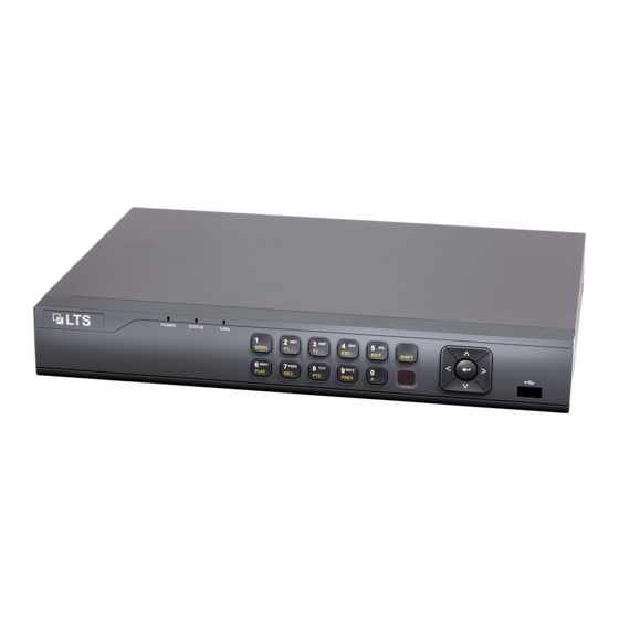
Digital Video Recorder Quick Start Guide Chapter1 Panels Description 1.1 Front Panel The front panel vaires according to different models. Please refer to the actual product. Figure 1‐1 Front Panel Table 1‐1 Description of Front Panel Name Function Description POWER: The POWER indicator turns green when NVR is powered up. - Page 8 Digital Video Recorder Quick Start Guide Name Function Description Enter numeral “5”; Enter letters “JKL”; 5/JKL/EDIT: Delete characters before cursor; Check the checkbox and select the ON/OFF switch; Start/stop record clipping in playback. Enter numeral “6”; 6/MNO/PLAY: Enter letters “MNO”; Playback, for direct access to playback interface.
-
Page 9: Rear Panel
Digital Video Recorder Quick Start Guide Name Function Description And in auto sequence view mode, the buttons can be used to pause or resume auto sequence. Receiver for IR remote. IR Receiver 1.2 Rear Panel The rear panel vaires according to different models. Please refer to the actual product. ... - Page 10 Digital Video Recorder Quick Start Guide RCA connector AUDIO IN RS-485 Connector for RS-485 devices. DC 12V power supply. Power Supply Power Switch Switch for turning on/off the device. Ground. Alarm In/Out Connector for alarm input/output. Available from A1 Security Cameras www.a1securitycameras.com email: sales@a1securitycameras.com...
-
Page 11: Chapter 2 Installation And Connections
Digital Video Recorder Quick Start Guide Chapter 2 Installation and Connections 2.1 DVR Installation During installation of the DVR: Use brackets for rack mounting. Ensure ample room for audio and video cables. When routing cables, ensure that the bend radius of the cables are no less than five times than its diameter. - Page 12 Digital Video Recorder Quick Start Guide Figure 2‐1 Remove Cover Step 2 Connect one end of the data cable to the motherboard of DVR and the other end to the HDD. Figure 2‐2 Connect Data Cable Step 3 Connect the power cable to the HDD. Figure 2‐3 Connect Power Cable Step 4 Place the HDD on the bottom of the device and then fasten the screws on the bottom to fix the HDD.
- Page 13 Digital Video Recorder Quick Start Guide Figure 2‐4 Fix Hard Disk Step 5 Re‐install the cover of the DVR and fasten screws. Available from A1 Security Cameras www.a1securitycameras.com email: sales@a1securitycameras.com...
-
Page 14: Rs-485 And Controller Connection
Digital Video Recorder Quick Start Guide 2.3 RS‐485 and Controller Connection Typical Connection: Figure 2‐5 Controller Connection A To connect PTZ to the DVR: Step 1 Disconnect pluggable block from the RS‐485 terminal block. Step 2 Press and hold the orange part of the pluggable block; insert signal cables into slots and release the orange part. -
Page 15: Hdd Storage Calculation Chart
Digital Video Recorder Quick Start Guide 2.4 HDD Storage Calculation Chart The following chart shows an estimation of storage space used based on recording at one channel for an hour at a fixed bit rate. Available from A1 Security Cameras www.a1securitycameras.com email: sales@a1securitycameras.com... - Page 16 Digital Video Recorder Quick Start Guide Bit Rate Storage Used 128K 160K 192K 224K 256K 112M 320K 140M 384K 168M 448K 196M 512K 225M 640K 281M 768K 337M 896K 393M 1024K 450M 1280K 562M 1536K 675M 1792K 787M 2048K 900M 4096K 1.76G 8192K...
-
Page 17: Chapter 3 Menu Operation
Digital Video Recorder Quick Start Guide Chapter 3 Menu Operation 3.1 Menu Structure The menu structure varies according to different models. Figure 3‐1 Menu Structure 3.2 Startup and Shutdown Proper startup and shutdown procedures are crucial to expanding the life of the DVR. To start your DVR: Step 1 Check the power supply is plugged into an electrical outlet. -
Page 18: Activating Your Device
Digital Video Recorder Quick Start Guide Step 2 Press the POWER button on the front panel. The Power LED should turn blue. The unit will begin to start. After the device starts up, the wizard will guide you through the initial settings, including modifying password, date and time settings, network settings, HDD initializing, and recording. - Page 19 Digital Video Recorder Quick Start Guide STRONG PASSWORD RECOMMENDED–We highly recommend you create a strong password of your own choosing (Using a minimum of 8 characters, including at least three of the following categories: upper case letters, lower case letters, numbers, and special characters.) in order to increase the security of your product.
-
Page 20: Using The Unlock Pattern For Login
Digital Video Recorder Quick Start Guide Figure 3‐6 Export GUID Step 5 After exporting GUID, the Attention box pops up as below. Click Yes to duplicate the password or No to cancel it. Figure 3‐7 Duplicate the Password 3.4 Using the Unlock Pattern for Login For the Admin user, you can configure the unlock pattern for device login. -
Page 21: Login And Logout
Digital Video Recorder Quick Start Guide Connect at least 4 dots to draw the pattern. Each dot can be connected for once only. Step 2 Draw the same pattern again to confirm it. When the two patterns match, the pattern is configured successfully. - Page 22 Digital Video Recorder Quick Start Guide Clear‐text password is supported. Click the icon and you can see the clear text of the password. Click the icon again and the content of the password restores invisible. In the Login interface, for the admin, if you have entered the wrong password for 7 times, the account will be locked for 60 seconds.
-
Page 23: User Logout
Digital Video Recorder Quick Start Guide Figure 3‐14 Reset Password 2) Input the new password and confirm the password. 3) Click OK to save the new password. Then the Attention box pops up as shown below. Figure 3‐15 GUID File Imported 4) Click OK and the Attention box as below pops up to remind you to duplicate the password of the device to IP cameras that are connected with default protocol. -
Page 24: Using The Setup Wizard
Digital Video Recorder Quick Start Guide Menu > Shutdown Figure 3‐17 Logout Step 2 Click Logout. After you have logged out the system, menu operation on the screen is invalid. It is required to input a user name and password to unlock the system. 3.6 Using the Setup Wizard The Setup Wizard can walk you through some important settings of the device. -
Page 25: Network Settings
Digital Video Recorder Quick Start Guide Figure 3‐19 View Signal Input Type Step 2 You can enable 5 MP Long Distance Transmission for the HD and AHD signal input. Follow the steps below to enable the function. 1) Click to enter the 5 MP Long Distance Transmission Settings interface. Figure 3‐20 5 MP Long Distance Transmission Settings 2) Check the checkbox to enable 5 MP Long Distance Transmission of the selected channel. -
Page 26: Adding Ip Cameras
Digital Video Recorder Quick Start Guide Figure 3‐21 Network Settings Step 2 Select the General tab. Step 3 In the General Settings interface, you can configure the following settings: NIC Type, IPv4 Address, IPv4 Gateway, MTU and DNS Server. If the DHCP server is available, you can check the checkbox of DHCP to automatically obtain an IP address and other network settings from that server. - Page 27 Digital Video Recorder Quick Start Guide Step 1 Select the Add IP Camera option from the right‐click menu in live view mode or click Menu> Camera> Camera to enter the IP camera management interface. Figure 3‐22 Add IP Camera Step 2 Select the IP camera from the list and click the button to add the camera (with the same admin password of the DVR’s).
-
Page 28: Live View
Digital Video Recorder Quick Start Guide You can choose to custom add the IP camera by editing the parameters in the corresponding text field and then click the Add button to add it. 3.10 Live View Icons are provided on screen in Live View mode to indicate camera status. These icons include: Live View Icons In the live view mode, there are icons at the upper‐right corner of the screen for each... -
Page 29: Playback
Digital Video Recorder Quick Start Guide 3.12 Playback The recorded video files and pictures on the hard disk can be played back in the following modes: instant playback, all‐day playback for the specified channel, and playback by normal/event/smart/tag/system logs/sub‐periods/external file search/picture. - Page 30 Digital Video Recorder Quick Start Guide Figure 3‐25 Show VCA Information in Smart Playback Step 4 (Optional) Select the channel(s) to execute simultaneous playback of multiple channels. Available from A1 Security Cameras www.a1securitycameras.com email: sales@a1securitycameras.com...
-
Page 31: Chapter 4 Accessing By Web Browser
Digital Video Recorder Quick Start Guide Chapter 4 Accessing by Web Browser You shall acknowledge that the use of the product with Internet access might be under network security risks. For avoidance of any network attacks and information leakage, please strengthen your own protection. If the product does not work properly, please contact with your dealer or the nearest service center. - Page 32 Digital Video Recorder Quick Start Guide STRONG PASSWORD RECOMMENDED–We highly recommend you create a strong password of your own choosing (Using a minimum of 8 characters, including at least three of the following categories: upper case letters, lower case letters, numbers, and special characters.) in order to increase the security of your product.
Need help?
Do you have a question about the LTD8308K-ETC and is the answer not in the manual?
Questions and answers