Table of Contents
Advertisement
Quick Links
PCE Americas Inc.
PCE Instruments UK Ltd.
711 Commerce Way
Units 12/13
Suite 8
Southpoint Business Park
Jupiter
Ensign way
FL-33458
Hampshire / Southampton
USA
United Kingdom, SO31 4RF
From outside US: +1
From outside UK: +44
Tel: (561) 320-9162
Tel: (0) 2380 98703 0
Fax: (561) 320-9176
Fax: (0) 2380 98703 9
info@pce-americas.com
info@pce-instruments.com
www.pce-instruments.com/english
www.pce-instruments.com
Manual
AC/DC Clamp Meter PCE-DC 41
Version 1.1
Date of creation: 07.07.2015
Date of last change: 05.08.2015
Advertisement
Table of Contents

Subscribe to Our Youtube Channel
Related Manuals for PCE Instruments PCE-DC 41


Summary of Contents for PCE Instruments PCE-DC 41
- Page 1 From outside UK: +44 Tel: (561) 320-9162 Tel: (0) 2380 98703 0 Fax: (561) 320-9176 Fax: (0) 2380 98703 9 info@pce-americas.com info@pce-instruments.com www.pce-instruments.com/english www.pce-instruments.com Manual AC/DC Clamp Meter PCE-DC 41 Version 1.1 Date of creation: 07.07.2015 Date of last change: 05.08.2015...
-
Page 2: Table Of Contents
AC current measurement ....................... 9 5.1.4 DC current measurement ....................... 9 5.1.5 Resistance measurement ......................10 5.1.6 Continuity test with buzzer ......................10 Battery replacement ......................... 11 Maintenance ..........................11 Cleaning............................ 11 Contact ........................12 PCE Instruments UK ........................ 12 PCE Americas .......................... 12... -
Page 3: Introduction
Double insulation. Safety instructions Please read this manual carefully and completely before you use the device for the first time. The device may only be used by qualified personnel and repaired by PCE Instruments personnel. There is no warranty damages... -
Page 4: Specifications
Manual Specifications General Display 4- digit LCD, maximum reading 6200 Polarity negative signal is indicated by icon Sampling rate 3 times/s Power supply 2 x 1.5 V AAA batteries approx. 50 hours (without buzzer and backlight Battery life function) Battery level indication insufficient battery voltage is indicated by icon after 30 minutes of inactivity to save battery... -
Page 5: Electrical
Manual Electrical Direct voltage Range Resolution Accuracy 600 V 0.1 V ±1 % + 2 digits Input impedance: 1 MΩ Direct voltage (peak model) Range Resolution Accuracy 600 V 0.1 V ±1.5 % + 8 digits Input impedance: 1 MΩ Alternating voltage Range Resolution... -
Page 6: System Description
Manual System description Display Auto Power Off indication Polarity indication Battery level indication (low battery) Alternating-current source indication Direct-current source indication Current measurement indication Voltage measurement indication Data Hold indication Peak data indication Continuity test indication Resistance measurement indication Zero measurement indication... -
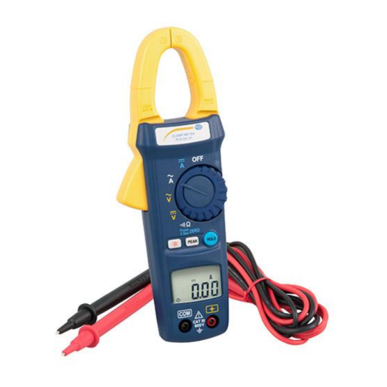
Page 7: Front And Rear
Manual Front and rear Current sensing clamp Lever to open clamp Dial for function selection PEAK key Backlight key HOLD key LC display COM input terminal Positive input terminal Battery compartment Key functions 4.3.1 HOLD function You can freeze the current value in the display by pressing the HOLD key. To deactivate this function, press the HOLD key once again. -
Page 8: Instructions
Manual Instructions Measurement 5.1.1 AC voltage measurement Switch the main function selector to Connect the red test lead to the + terminal and the black test lead to the COM terminal. Touch the test circuit with the tips of the test leads and read the result which will appear in the LCD. -
Page 9: Ac Current Measurement
Manual 5.1.3 AC current measurement For safety reasons, it is recommended to disconnect the test leads from the meter before carrying out this measurement. Then switch the main function selector to . Open the clamp by pushing the lever and insert the cable to be measured into the hole. -
Page 10: Resistance Measurement
Manual 5.1.5 Resistance measurement Before taking a resistance measurement, make sure that the power is cut off from the circuit and that all capacitors are discharged. Then switch the main function selector to . Connect the red test lead to the + terminal and the black test lead to the COM terminal. -
Page 11: Battery Replacement
In order to comply with the EU directive 2012/19/EU we take our devices back. We either re-use them or give them to a recycling company which disposes of the devices in line with law. If you have any questions, please contact PCE Instruments. Maintenance Warning! Before opening the meter, disconnect both test leads and close the cover. -
Page 12: Contact
Contact If you have any questions about our range of products or measuring instruments please contact PCE Instruments. PCE Instruments UK By post: PCE Instruments UK Ltd. Units 12/13 Southpoint Business Park Ensign Way, Southampton Hampshire United Kingdom, SO31 4RF...
Need help?
Do you have a question about the PCE-DC 41 and is the answer not in the manual?
Questions and answers