Table of Contents
Advertisement
Quick Links
PCE Americas Inc.
PCE Instruments UK Ltd.
711 Commerce Way
Units 12/13
Suite 8
Southpoint Business Park
Jupiter
Ensign way
FL-33458
Hampshire / Southampton
USA
United Kingdom, SO31 4RF
From outside US: +1
From outside UK: +44
Tel: (561) 320-9162
Tel: (0) 2380 98703 0
Fax: (561) 320-9176
Fax: (0) 2380 98703 9
info@pce-americas.com
info@pce-instruments.com
www.pce-instruments.com/english
www.pce-instruments.com
Manual
Accelerometer PCE-VM 40A/B
Version 1.0
Date of creation: 20.10.2015
Date of last change: 04.07.2016
Advertisement
Table of Contents

Related Manuals for PCE Instruments PCE-VM 40A


Summary of Contents for PCE Instruments PCE-VM 40A
- Page 1 PCE Americas Inc. PCE Instruments UK Ltd. 711 Commerce Way Units 12/13 Suite 8 Southpoint Business Park Jupiter Ensign way FL-33458 Hampshire / Southampton United Kingdom, SO31 4RF From outside US: +1 From outside UK: +44 Tel: (561) 320-9162 Tel: (0) 2380 98703 0...
-
Page 2: Table Of Contents
Firmware update ........................34 5.23 Charging the battery ......................... 34 5.24 External power supply ......................35 5.25 Reset ............................35 5.26 Mounting ........................... 36 Calibration ......................37 Disposal ......................... 37 Contact ........................37 PCE Instruments UK ........................ 37 PCE Americas .......................... 37... -
Page 3: Introduction
Please read this manual carefully and completely before you use the device for the first time. The device may only be used by qualified personnel and repaired by PCE Instruments personnel. There is no warranty of damages or injuries caused by non-observance of the manual. -
Page 4: Specifications
Manual Specifications Measuring variable Peak value of vibration velocity Peak value of vibration acceleration Standards DIN 4150-3; BS 7385, SN 640312A Vibration sensor Triaxial piezoelectric shear-type-accelerometer 0.001 … 15 m/s² Indication range vibration velocity (peak value) 0.01 … 2400 mm/s at 1 Hz Indication range vibration acceleration (peak value) 0.01 …... -
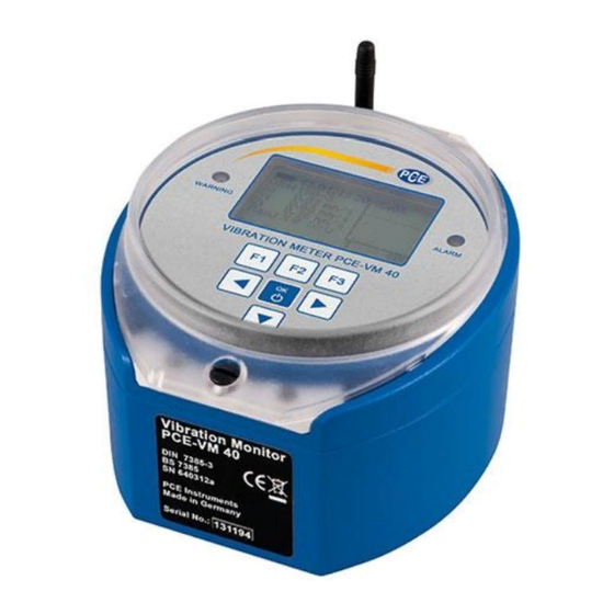
Page 5: System Description
Manual System description mobile phone antenna relay output USB / headset connector charging socket... -
Page 6: Operation
Manual Operation Selecting the measurement mode Switch on the PCE-VM 40 by pressing the ON-OFF button. After the start screen, the measurement value display with the most recently selected settings appears. Press F3 to open the main window and select “measuring mode”. -
Page 7: Measuring In Accordance With Din 4150-3
Manual Measuring in accordance with DIN 4150-3 Measurement procedure DIN 4150-3 is the most widely applied standard internationally for measuring structural vibrations. The measurement procedure can be found in a similar form in other national standards, for example the Italian UNI 9916. - Page 8 Manual For sustained vibration, the following reference values apply: Reference values for vibration velocity v for analysing the effects of sustained vibration Building type Upper ceiling level, all frequencies Direction X /Y (horizontal) Z (vertical) Reinforced or framed structures 10 mm/s 10 mm/s industrial and heavy commercial buildings...
- Page 9 Manual Measurements with the PCE-VM 40 After choosing the operating mode „DIN 4150-3“, please select whether you will be measuring short-time or sustained vibration. Please select the building type next: The following types are available, when selecting “pipeline”: In case of short-time vibrations, the measurement location needs to be selected: The standard frequency range is 1 …...
-
Page 10: Measuring In Accordance With Bs7385
Manual The three peak values X/Y/Z of the vibration velocity and the highest amplitude together with its main frequency are displayed every second. On the right side of the screen a graph displays this value in the frequency range. The diagram is scaled according to the limit curve. Higher magnitudes will be cut off. Note: For the measurement of floor ceiling vibrations, there are different reference values for the vertical (Z) direction. - Page 11 Manual Measurements with the PCE-VM 40 Once you have selected the measuring mode “BS7385”, select the building type to be assessed. In the next menu, select the frequency range: Press F3 to exit the menu and to go the measurement value display The three peak values X/Y/Z of the vibration velocity and the highest amplitude together with its main frequency are displayed every second.
-
Page 12: Measuring In Accordance With Sn 640312A
Manual Measuring in accordance with SN 640312a Measurement procedure The Swiss Standard SN 640312a is also based on the peak values of the vibration velocity. However, it uses the vector sum as assessment parameter: It measures between 5 and 150 Hz. The frequency range is divided into three sections: 8 to 30 Hz, 30 to 60 Hz and >60 Hz. -
Page 13: Non-Standardized Measurements
Manual The vector sum of the vibration velocity in the three directions X/Y/Z and the highest amplitude together with its main frequency are displayed every second. On the right side of the screen, a graph displays this value in the frequency range. The diagram is scaled to the limit curve. Higher magnitudes will be cut off. If the limit value is exceeded, “ALARM”... -
Page 14: Overload Indication
Manual Overload indication If the vibration magnitude exceeds the limits shown in the Technical Data section, the PCE-VM 40 will indicate “OVERLOAD” instead of the measuring value for the respective direction. In addition, the warning and alarm LEDs flash simultaneously. Due to integration, the overload limit for the vibration velocity is frequency-dependent. - Page 15 Manual Setting for recording data To start recording, open the main menu by pressing F3 and select “Recording”. Select “start”. Now you can define the events (triggers), when the data should be saved. In the setting “Warning/Alarm”, the measurement value is saved as soon as a change in status occurs, as follows: Normal to Warning Normal to Alarm...
- Page 16 Manual The PCE-VM 40 also offers you the possibility of saving measurements at pre-set time intervals. The time intervals are to be entered in seconds, with a minimum of 5 seconds. The time interval recording can also be combined with the status change recording (“Event and time control”).
-
Page 17: Displaying Saved Data
Manual Displaying saved data After recording, you can view the saved measurements in the “Recording” menu. Select the menu point “View/edit/delete files” and then use the arrow keys ▲▼ to select the data file you wish to view. A data file is displayed by its number and name, together with the start time, chosen standard and trigger source. -
Page 18: Deleting The Data Memory
Manual When the data was measured in line with SN 640312a, you see the vector sum, otherwise you will see the three measuring values of X / Y / Z. The main frequency f(max) of the highest value is also displayed. Use the ▲... -
Page 19: Receiving Alerts Via Sms (Pce-Vm 40B)
Manual In addition, you can determine whether the relay should stay energized (“Latching”) or de-energize after the event finishes, until the OK-button is pressed (“Non-latching”). Note: The relay function will be activated after a delay of 30 seconds after leaving the menu. The figure below shows the output socket and its contact assignment. - Page 20 Manual Open the SIM card holder by sliding its upper part across and opening it, as shown. Place the SIM card in the holder, as shown, and return the holder to its original position. Then put the lid back on. Please ensure that you do not trap any cables while doing this and please check the position of the flat cable plug which establishes the connection to the sockets.
-
Page 21: Connection To A Mobile Network
Manual 5.14 Connection to a mobile network Once you have inserted the SIM card, open “Alarms/GSM” from the main menu and then select “GSM/SMS”. When you use the card for the first time, you will be asked to enter the PIN. If the card has been locked (e. -
Page 22: Sms Alerts
Manual 5.15 SMS alerts The PCE-VM 40B can send SMS messages including measurement values and the time when a limit value is exceeded. To set up the automatic SMS alerts, you need to enter the following information in the sub-menu “SMS Alert Settings”. Within the submenu “Max. -
Page 23: Phone Book
Manual The message will be displayed on the recipient’s mobile (varying slightly dependent on the receiving phone) as shown in the figure below. Under the heading “!!VIBRATION ALERT!!”, the instrument name is displayed. Below this, the date and time of the alarm event are displayed, followed by the three vibration values measured at the time of the alarm signal. -
Page 24: Writing An Sms
Manual 5.17 Writing an SMS In the menu “Write SMS” under “Alarm/GSM”, sub-menu “GSM/SMS” you can write and send a short text message. You will then need to enter the recipient’s telephone number or select it from the phone book. Next you can enter 4 rows of text, each up to a maximum of 20 characters long. -
Page 25: Disconnect From Mobile Network
Manual You can select the telephone number from the phone book or enter it directly. Press OK to start the call. Press OK again to end the call. 5.19 Disconnect from mobile network In the sub-menu “GSM/SMS”, you will find the option “close connection”. Press OK to confirm you want to close the connection with the mobile phone network To enlarge the life of the rechargeable battery, we recommend to close the connection with the mobile network when not in use. - Page 26 Manual Keypad lock To prevent manipulation during ongoing monitoring, it can be advantageous to activate the key lock. This function can be found in the main menu under “Key Lock”. When the key lock has been activated and you left the menu, you may only retrieve information using the keys F1 and F2.
- Page 27 Manual Date and time To retrace vibration events in the saved values, the exact date and time are important. To set the date and time, open the main menu by pressing F3. From the main menu, go to the menu option “Device settings”...
-
Page 28: Data Transfer
Manual 5.21 Data transfer Connect the device to a PC The PCE-VM 40 has a USB interface. For connecting to a PC, you can use the VM2x USB cable, which is connected to the second socket on the PCE-VM 40. As soon as the other end of the cable is connected to the computer USB socket, the device identification begins. - Page 29 Manual Software VM40MDB The PC software VM40MDB is used to archive and display measuring data from the PCE-VM 40. In addition, it generates reports in accordance with the relevant standards. You can download the license-free software from the web page www.pce-instruments.com VM40MDB runs under Windows 7, 8 and 8.1.
- Page 30 Manual VM40MDB can archive all measurements ever recorded with the PCE-VM 40. They can also come from different PCE-VM 40 units. To search in larger amounts of data, there are filter functions on the right side of the header list. You may search for a certain range of calendar dates, parts of the file name or the content of the “place”...
- Page 31 Manual...
- Page 32 Manual...
- Page 33 Manual Apart from the report function, you can display the measuring data graphically by selecting the menu tab “Measurement chart”. You will see all measurements in a magnitude/time diagram. Displayed events can be filtered depending on their trigger event. For example, you may want to see alarm events only. By right mouse click, individual axes can be disabled.
-
Page 34: Firmware Update
1. Download the firmware file vm40.hex from the above-named website. This contains the firmware for the instruments PCE-VM 40A and PCE-VM 40B. 2. Also download the program “Firmware Updater” from the above-named website and install it on your PC. -
Page 35: External Power Supply
Manual 5.24 External power supply For measurements of very long duration, an external power supply is recommended. To operate the PCE-VM 40 using an external power supply, connect the USB cable provided with the device’s USB socket. To operate the device via USB power supply, you may use a standard USB power supply unit or alternatively a “USB Power Bank”. -
Page 36: Mounting
The cast aluminium case of the PCE-VM 40 is suitable for direct mounting because of its weight. However, we recommend using the tripod floor plate VM40-BP, available from PCE Instruments as an optional accessory. The VM40-BP has adjustable feet for aligning the axes, including exchangeable tips for different floor types. -
Page 37: Calibration
Due to the weight of the device and the required low frequencies and high amplitudes, a particular kind of vibration generator is needed. The calibration menu is not accessible to the user in order to avoid manipulation. PCE Instruments offers a calibration service. For calibrations in other laboratories, we also provide the necessary technical documentation, upon request. Disposal For the disposal of batteries, the 2006/66/EC directive of the European Parliament applies.
Need help?
Do you have a question about the PCE-VM 40A and is the answer not in the manual?
Questions and answers