
Related Manuals for GEA HG34P/e


Summary of Contents for GEA HG34P/e
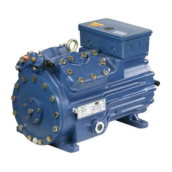
- Page 1 Bock HG34P/e Maintenance manual 96193-05.2021-D BOCK ® colour the world of tomorrow...
-
Page 2: Table Of Contents
About these instructions Read these instructions before assembly and before using the Liability and warranty compressor. This will avoid misunderstandings and prevent dama- ge. Improper assembly and use of the compressor can result in Manufacturer's liability and warranty are excluded if serious or fatal injury. -
Page 3: Safety
1 I Safety Safety instructions Target group of these instructions • Work on the compressor may only be carried out by persons whose technical training, skills and expe- rience along with their knowledge of pertinent regulations and documentation means that they are capa- ble of assessing the work to be carried out and detecting any possible dangers •... -
Page 4: Fault Diagnosis
2 I Fault diagnosis Fault diagnosis Function faults - Symptoms In case of malfunctions during compressor operation we recommend Function faults arising most frequently and their symptoms are: to prepare a measurement record for aiding the fault search: Compressor stoppage, compressor cutoff Pressure measurement: Discharge side, suction side, - Compressor does not start oil pressure... - Page 5 2 I Fault diagnosis Problem Possible cause Remedy Overload / Motor safety switch Two phase run Ensure three phase run is tripped Very unequal phase runs Determine and remove the cause Compressor cutoff Compressor starts and stops again Problem Possible cause Remedy Cutoff through lowpressure Suction pressure too low:...
- Page 6 2 I Fault diagnosis Problem Possible cause Remedy MP10 switched off Function / drive not working Check function / drive Motor overloaded Check operating conditions Undervoltage Determine and remove the cause Short circuit ON / OFF check control Starter contacts / shorted contacts / Check motor for winding damage / check earthed contacts shorted contacts...
- Page 7 2 I Fault diagnosis Problem Possible cause Remedy Discharge pipe temperature - Cooling insufficient - Check refrigerant filling too high - Adjust expansion valve - Short circuit between the discharge and the - Check gaskets on valve plate / suction side of the compressor change - Valve plate damage - Replace valve plate...
-
Page 8: Disassembly Of The Compressor
3 I Disassembly of the compressor Disassembly and assembly of the compressor WARNING! Before starting any work on the compressor: • Switch of the compressor and guard it against switching on. • Relieve the compressor from system pressure • Prevent air from infiltrating the system •... - Page 9 3 I Disassembly of the compressor Removal of the compressor from the refrigerant system Removal of the compressor from the system, shut-off valves remaining on the compressor - Extract the refrigerant from the system into a container which may be used for this refrigerant - Evacuate the systems including the compressor - Cut off the vacuum, humid air should not get into the system - Close the shut-off valves on the suction and discharge side;...
- Page 10 3 I Disassembly of the compressor Draining the oil Position in Parts list position: 480 parts list Tools: Spanner SW 17, Oil collection container > 1,5 liter Working course - The compressor has to be depressurized - Place the container in a way that the oil can flow into it 480, 482 - Loosen oil drain screw and unscrew - Drain off oil...
- Page 11 3 I Disassembly of the compressor Disconnecting the electrical connections Position in Parts list position: 2150, 1055, 1065, 1071 parts list Tools: Spanner SW 13 Working course 1055, - Remove terminal board and PTC terminal board 1065, 1071, 2150 Gußtoleranzen: Zeichn.-Nr.
- Page 12 3 I Disassembly of the compressor Remove housing cover suction side Position in Parts list position: 720, 721, 740 parts list Tools: Spanner SW 17 Working course - To collect leaking oil, protect the assembly area with absorbent material. Dispose of the material environmentally sound afterwards - Losen the screw at the housing cover and unscrew 720, 721 - Take off housing cover and seal...
- Page 13 3 I Disassembly of the compressor Remove rotor Position in Parts list position: 2130 parts list Tools: Spanner SW 17 Working course 800, 810, - Losen rotor screw - Pull off rotor from crankshaft - Take off feather key of crankshaft - Pull of washer between rotor and crankshaft Gußtoleranzen: Blatt:...
- Page 14 3 I Disassembly of the compressor Remove stator Position in Parts list position: 2130 parts list Tools: Spanner SW 13, Allen key Working course 1010, 1020 - Losen screw plug and the stator screw below - Pull out stator - Pay attention to the weight! Note: For 2 pole compressors the stator cannot be removed because it is built in while it is still warm.
- Page 15 72636 Frickenhausen Germany www.bock.de Freigab an dieser Zeichnung vor. Geprüft Maß Passung Freigabe GEA Bock GmbH - Benzstraße 7 - 72636 Frickenhausen - Germany als Animation sehen? Folgen Sie dem QR Code. Alternativer Link: http://www.youtube.com/watch?v=JNS9-4mNX7c Zust. Änderungsbeschreibung Zone Änderungs-Nr. Datum Bearb.
- Page 16 3 I Disassembly of the compressor Remove cylinder cover and valve plates Position in Parts list position: 170, 178, 180, 2000 parts list Tools: Spanner SW 17 Working course - if installed: To not remove thermal protection thermostat and capacity regulator, if necessary disconnect in terminal box - Losen screws at the cylinder cover and unscrew 170, 70,...
- Page 17 3 I Disassembly of the compressor Remove crankshaft Position in Parts list position: 2050 parts list Tools: Spanner SW 17 Working course - Take off feather key of crankshaft on oil pump side 2050 - Release crankshaft of the connecting rod and take it out Gußtoleranzen: Blatt: Maßstab:...
- Page 18 3 I Disassembly of the compressor Remove pistons and connecting rods Position in Parts list position: 2040 parts list Tools: Needle-nosed pliers Working course - Mark corresponding pistons of cylinder bore 2100, 2030 - Push out pistons and connecting rods towards the cylinder cover as far as it will go 290, 300 - Remove piston rings - Take out piston rings towards crankcase...
-
Page 19: Checking The Compressor Parts
4 I Checking the compressor parts Checking compressor parts for damages and wear Before re-using removed compressor parts we recommend that they be checked for usability. The wear limits listed below should be taken into consideration: Piston - cylinder bore 0,13 mm Connecting rod - piston pin 0,03 mm... - Page 20 4 I Checking the compressor parts Pistons There should be no visible damages on the piston crown and the piston walls. The grooves for the piston rings must be clean and undamaged. Check the condition of the piston rings for wear, fractures and other irregularities.
-
Page 21: Assembly Of Compressor
4 I Checking the compressor parts Oil filter / suction filter The filter screen must be in an undamaged condition. Dirt and residues have to be removed. If necessary, the filter have to be cleanded with compressed air or replaced with new ones. In case of larger compressor damages which necessitate a complete disassembly of the compressor, we recommend in principle the replacement of the valve plates, the piston rings and all seals. - Page 22 5 I Assembly of compressor Assembly of the pistons / connection Position in Parts list position: 2040 parts list Tools: Needle-nosed pliers Working course 2100, 270, - Assemble piston and connecting rod with piston pin, use some oil for easier assembly - Mount circlips with pliers on both sides of the piston pins Möchten Sie diesen Montageschritt als Animation sehen?
- Page 23 5 I Assembly of compressor Fitting the piston / connecting Position in Parts list position: 2040 parts list Tools: Piston ring plier Working course We recommend cleaning the housing from the inside before assembly - Apply a little oil to the cylinder bore - Insert pistons/connecting rods from below into the cylinder liners ->...
- Page 24 5 I Assembly of compressor Fitting the crankshaft Position in Parts list position: 2050 parts list Tools: Working course - Apply bearing surface with oil - Insert crankshaft. Important: Alle connecting rods have to be moved axially and radially on the crankshaft - Insert feather key on oil pump side Gußtoleranzen: Blatt:...
- Page 25 5 I Assembly of compressor Installation of cylinder cover Position in Parts list position: 170, 180, 2000 parts list Tools: Spanner SW 17 Working course 50, 60, 70, - Slightly oil seals - Install seals below, valves plates, seals above and cylinder cover together - Tighten the screws crosswise 75 Nm 75 Nm...
- Page 26 Abnehmer oder Dritte ist nicht gestattet. Geprüft Erstellt Wir behalten uns alle Rechte, gemäß DIN ISO 16016 an dieser Zeichnung vor. Maß Passung Geprüft GEA Bock GmbH - Benzstraße 7 - 72636 Frickenhausen - Germany Freigabe Maß Passung Zust. Änderungsbeschreibung Zone Änderungs-Nr.
- Page 27 5 I Assembly of compressor Install stator Position in Parts list position: 2130 parts list Tools: Spanner SW 13, SW 17, needle-nosed pliers Working course 1179 - Regard alignment of feather key - Stator, the parts can only be installed aligned - Push stator into the housing as far as it goes 1020 - Screw stator screw in.
- Page 28 5 I Assembly of compressor Install terminal board Position in Parts list position: 2150, 1055, 1060, 1065, 1071 parts list Tools: Spanner SW 13 Working course 1055, 1065 - Slightly oil seals 2150 - Install terminal board and PTC-terminal board SW 10 15 Nm Möchten Sie diesen Montageschritt...
- Page 29 Mounting the terminal board Montage de la planche à bornes er Reihenfolge. The terminal board is mounted in reverse order. Le montage sera réalisé dans le sens inverse des opérations. 5 I Assembly of compressor ppen des Note: When you tip the terminal board over, Nota : Suite au renversement de la planche the connection screws for the motor wires à...
- Page 30 5 I Assembly of compressor Install rotor Position in Parts list position: 2130 parts list Tools: Spanner SW 17 Working course - Push pulley on the crankshaft as far as is goes - Insert feather key into the crankshaft - Push the rotor on the crankshaft 810, 820 - Tighten screw with pulley and spring washer (and bolt spacer if necessary) 65 Nm...
- Page 31 5 I Assembly of compressor Install housing cover suction side Position in Parts list position: 720, 721, 740 parts list Tools: Spanner SW 17 Working course - Slighty oil seals 720, 740 - Screw the housing cover incl. seal, tighten screws crosswise 75 Nm Maßstab: Gußtoleranzen:...
- Page 32 5 I Assembly of compressor Finish installation and wire Position in Parts list position: parts list Tools: Working course - Do the electrical installation according to the diagram in the terminal box - Pay attention to the installation instruction of the compressor! - Close the cover at the terminal box - Do the next step, such as commissioning, according to the installation instructions of the compressor...
-
Page 33: Exploded Drawing
6 I Exploded drawing HG34e cast iron, HG34P 2-pole cast iron, HG34P HC-compressors... - Page 34 6 I Exploded drawing HG34e aluminium compressor 4-pole...
- Page 35 6 I Exploded drawing HG34P aluminium compressor 2-pole and K-Design...
- Page 36 6 I Exploded drawing HG34e for R407C, HG34P for R410A...
- Page 40 BOCK ® Bock GmbH Benzstraße 7 72636 Frickenhausen Germany Tel +49 7022 9454-0 Fax +49 7022 9454-137 www.bock.de © Bock GmbH. All rights reserved. Subject to modifications.
Need help?
Do you have a question about the HG34P/e and is the answer not in the manual?
Questions and answers