Table of Contents

Subscribe to Our Youtube Channel
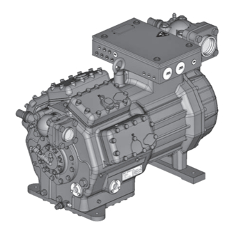
Related Manuals for GEA Bock HG8 Series


Summary of Contents for GEA Bock HG8 Series
- Page 1 GEA Bock HG8 Assembly instructions 09790-02.2018-Gb Translation of the original instructions HG8/2470-4 HG8/2470-4 S HGX8/2470-4 HGX8/2470-4 S HG8/2830-4 HG8/2830-4 S HGX8/2830-4 HGX8/2830-4 S HG8/3220-4 HG8/3220-4 S HGX8/3220-4 HGX8/3220-4 S...
-
Page 2: Safety 4
Observe the safety instructions contained in these instructions. These instructions must be passed onto the end customer along with the unit in which the compres- sor is installed. Manufacturer GEA Bock GmbH 72636 Frickenhausen Contact GEA Bock GmbH Benzstraße 7... -
Page 3: Table Of Contents
Contents Page Safety 1.1 Identification of safety instructions 1.2 Qualifications required of personnel 1.3 General safety instructions 1.4 Intended use Product description 2.1 Short description 2.2 Name plate 2.3 Type key Areas of application 3.1 Refrigerants 3.2 Oil charge 3.3 Limits of application Compressor assembly 4.1 Storage and transportation 4.2 Setting up 4.3 Pipe connections 4.4 Pipes... -
Page 4: Safety
1| Safety 1.1 Identification of safety instructions: DANGER Indicates a dangerous situation which, if not avoided, will cause immediate fatal or serious injury. WARNING Indicates a dangerous situation which, if not avoided, may cause fatal or serious injury. CAUTION Indicates a dangerous situation which, if not avoided, may cause fairly severe or minor injury. -
Page 5: General Safety Instructions
These assembly instructions describe the standard version of the compressor named in the title man- ufactured by GEA. GEA refrigerating compressors are intended for installation in a machine (within the EU according to the EU Directives 2006/42/EC Machinery Directive, 2014/68/EU Pressure Equipment Directive). -
Page 6: Product Description
2| Product description 2.1 Short description • Semi-hermetic eight-cylinder reciprocating compressor with suction-gas cooled drive motor. • The stream of refrigerant sucked out of the evaporator flows over the motor and cools it intensively. In this way, the motor can be kept at a relatively low temperature level, particularly under high loads. -
Page 7: Type Key
2| Product description 2.2 Name plate (example) GEA Bock GmbH 72636 Frickenhausen, Germany Y/YY HGX8/3220-4 AS12345-A018 AW09529A047 Y/YY SE 55 Fig. 2 Type designation Voltage, circuit, frequency 50 Hz Machine number Nominal rotation speed Type code Displacement Maximum operating current 10 Voltage, circuit, frequency... -
Page 8: Areas Of Application
3| Areas of application 3.1 Refrigerants • HFKW / HFC: R134a, R404A/R507, R407C • (H)FCKW / (H)CFC: 3.2 Oil charge The compressors are filled at the factory with the following oil type: - for R134a, R404A/R507, R407C FUCHS Reniso Triton SE 55 - for R22 FUCHS Reniso SP 46 Compressors with ester oil charge (FUCHS Reniso Triton SE 55) are marked with an X in the type designation (e.g. - Page 9 Unlimited application range Supplementary cooling or reduced suction gas temperature R134a Supplementary cooling and reduced suction gas temperature Motor version S (more powerful motor) Fig. 4 Evaporation temperature (°C) Condensing temperature (°C) Suction gas superheat (K) Suction gas temperature (°C) HGX8/2470-4 - HGX8/2830-4 - R407C HGX8/3220-4...
-
Page 10: Compressor Assembly
4| Compressor assembly INFO New compressors are factory-filled with inert gas. Leave this ser- vice charge in the compressor for as long as possible and prevent the ingress of air. Check the compressor for transport damage before starting any work. 4.1 Storage and transportation Storage at (-30 °C) - (+70 °C), maximum permissible relative humid- ity 10 % - 95 %, no condensation. -
Page 11: Pipe Connections
4| Compressor assembly 4.3 Pipe connections ATTENTION Damage possible. Superheating can damage the valve. Remove the pipe supports from the valve for soldering. Only solder using inert gas to inhibit oxidation products (scale). The discharge gas connection can be moved upwards with an adapter (accessory). -
Page 12: Laying Suction And Pressure Lines
4| Compressor assembly 4.5 Laying suction and pressure lines ATTENTION Improperly installed pipes can cause cracks and tears, the result being a loss of refrigerant. INFO Proper layout of the suction and discharge lines directly after the compressor is integral to the system’s smooth running and vibration behaviour. -
Page 13: Operating The Shut-Off Valves
4| Compressor assembly 4.6 Operating the shut-off valves Before opening or closing the shut-off valve, release the valve spindle seal by approx. 1/4 of a turn counter-clockwise. After activating the shut-off valve, re-tighten the adjustable valve spindle seal clockwise. Release Tighten Valve spindle seal Fig. -
Page 14: Electrical Connection 14 D
5| Electrical connection Electrical connection DANGER Risk of electric shock! High voltage! Only carry out work when the electrical system is disconnected from the power supply! ATTENTION When attaching accessories with an electrical cable, a minimum bending radius of 3 x the cable diameter must be maintained for laying the cable. -
Page 15: Standard Motor, Design For Direct Or Partial Winding Start Gb
5| Electrical connection 5.2 Standard motor, design for direct or partial winding start Designation on the name plate Sticker on the terminal box Y/YY Y/YY Compressors with this marking are suitable for direct or partial winding start. The motor winding is subdivided into two parts: Part winding 1 = 50% and part winding 2 = 50%. - Page 16 5.3 Basic circuit diagram for part winding start with standard motor F1.2 F1.1 I=33% I=66% I> I> I> I> I> I> F1.1 F1.2 X SS X1 L1 L1 N N 43 43 11 /YYY X2 1 MP10 P - oil Compressor terminal box Anschlußkasten Verdichter R2.4...
- Page 17 L1.1 L2.1 L3.1 L1.2 P> P< P-Öl Release switch (thermostat) Main switch Compressor motor Mains contactor (part winding 1) Mains contactor (part winding 2) Delay relay max. 1s Oil sump heater Control voltage switch Terminal strip in the external switch cabinet PW MP10 BOCK COMPRESSORS...
-
Page 18: Special Motor: Design For Direct Or Star-Delta Start F
5| Electrical connection 5.4 Sondermotor: Ausführung für Direkt- oder Stern-Dreieck-Anlauf 5.4 Special motor: design for direct or star-delta start Für den Stern-Dreieck-Anlauf ist eine mechanische Anlaufentlastung mit Bypass-Magnetventil A mechanical unloaded start with bypass solenoid valve (accessories) is required for the (Zubehör) erforderlich. star-delta start. Bezeichnung auf dem Typschild Aufkleber auf Klemmenkasten Designation on the name plate Sticker on the terminal box ∆... - Page 19 5| Electrical connection Star-delta start-up is only possible for ∆ (230 V) power supply. Example: 230 V Δ 400 V Y Direct start only Direct start Star-delta-start In the factory the motor is wired for direct starting at high voltage. The brides are to be removed for star delta starting at low voltage.
-
Page 20: Circuit Diagram For Star-Delta Start 230 V ∆ / 400 V Y
5.5 Circuit diagram for star-delta start 230 V ∆ / 400 V Y F1.2 F1.1 I=33% I=66% I> I> I> I> I> I> F1.1 F1.2 X SS ˜ X1 L1 L1 N N 43 43 11 X2 1 MP10 Compressor terminal box Anschlußkasten Verdichter R2.1 R2.2... - Page 21 L1.1 L2.1 L3.1 L1.2 P> P< P-Öl Main switch Compressor motor Mains contactor Δ-contactor Y-contactor Delay relay max. 1s Delay relay for contactor switch-over Oil sump heater Control voltage switch Terminal strip in the external switch cabinet PW MP10 BOCK COMPRESSORS...
-
Page 22: Electronic Trigger Unit Mp10
5| Electrical connection 5.6 Electronic trigger unit MP10 The compressor motor is fitted with cold conductor temperature sensors (PTC) connected to the elec- tronic trigger unit MP10 in the terminal box. Readiness to operate is signalled by the H3 LED (green) after the power supply is applied. In the case of excess temperature in the motor winding, the unit switches off the compressor and the H1 LED lights red. -
Page 23: Functional Test Of The Trigger Unit Mp10 I
5| Electrical connection 5.8 Function test of the trigger unit MP10 Before start-up, troubleshooting or making changes to the control power circuit, check the functionality of the trigger unit: LED H1 LED H2 LED H3 Procedure green • Interrupt power supply (L1 or S1) •... -
Page 24: Oil Sump Heater (Accessories) Ru
5 | Electrical connection 5.9 Oil sump heater (accessories) When the compressor is at a standstill, refrigerant diffuses into the lubricating oil of the compressors housing, depending on pressure and ambient temperature. This reduces the lubricating capacity of the oil. When the compressor starts up, the refrigerant contained in the oil evaporates out through the reduction in pressure. The consequences can be foaming and migration of the oil, causing oil shocks under certain circumstances. -
Page 25: Commissioning
6| Commissioning 6.1 Preparations for start-up INFO In order to protect the compressor against inadmissible operating conditions, high pressure and low pressure pressostats are manda- tory on the installation side. The compressor has undergone trials in the factory and all functions have been tested. There are therefore no special running-in instructions. -
Page 26: Refrigerant Charge
6| Commissioning 6.5 Refrigerant charge CAUTION Wear personal protective clothing such as goggles and protective gloves! Make sure that the suction and pressure line shut-off valves are open. With the compressor switched off, add the liquid refrigerant directly to the condenser or receiver, breaking the vacuum. If the refrigerant needs topping up after starting the compressor, it can be topped up in vapour form on the suction side, or, taking suitable precautions, also in liquid form at the inlet to the evaporator. -
Page 27: Connection Of Oil Level Regulator
6| Commissioning 6.8 Connection of oil level regulator Oil level regulation systems have proven themselves with parallel circuits of several compressors. The connection "0" is provided for installing an oil level regulator (see dimensions drawing). All common oil level regulators from AC&R, ESK and Carly as well as the OM3 TraxOil oil level regulation system from Alco can be connected directly without adapters (see Fig. -
Page 28: Maintenance
HG8 / ... 2470-4 (S) 2830-4 (S) 3220-4 (S) Designation Item No. Item No. Item No. Set of gaskets kit 80235 Valve plate kit 80199 Oil pump kit 80290 Oil sump heater kit (220-240 V) 80237 Only use genuine GEA spare parts! -
Page 29: Extract From The Lubricants Table
7.4 Extract from the lubricants table The oil type filled as standard in the factory is marked on the name plate . This oil type should be used as a preference. Alternatives are stated in the extract from our lubricants table below. Refrigerants GEA standard oil types Recommended alternatives Fuchs Reniso Triton SEZ 32 Esso/Mobil EAL Arctic 46 (e.g. -
Page 30: Accessories
8| Accessories 8.1 Start unloader (kit- Item No. 08981) A start unloader is necessary for Y/Δ start (special motor). • Fit the non-return valve in the discharge pipe • Rate the non-return valve according to the operating conditions. • Electrical trigger for the solenoid valve: closed idle •... -
Page 31: Capacity Controller (Item No. 08821)
Switching off Special accessories are only premounted in the factory if ordered specially by customer. Retrofitting is possible in full compliance with the safety instructions and repair instructions enclosed with the kits. Information about the use, operation, maintenance and servicing of the components is available in the printed literature or on the internet under www.gea.com. -
Page 32: Technical Data
9| Technical data Oil charge Weight 380-420 V Y/YY - 3 - 50 Hz PW 440-480 V Y/YY - 3 - 60 Hz PW PW = Part Winding Winding ratio : 50 % / 50 % No. of cylinders... -
Page 33: Dimensions And Connections
8182 nts to others without express authorization is ür den Fall der Patent-, Gebrauchsmuster- der Patent-, Gebrauchsmuster- GEA Bock GmbH - Benzstraße 7 - 72636 Frickenhau ent as well as the communication of its Maß / Dimension Passung / Clearance Änd.-Nr. - Page 34 10| Dimensions and connections Suction line see technical data, Chapter 9 Discharge line Connection suction side, not lockable 8 “ NPTF Connection suction side, lockable 16 “ UNF Connection suction side, not lockable 4 “ NPTF Connection discharge side, not lockable 8 “...
-
Page 35: Declaration Of Installation
European Union (in accordance with Machinery Directive 2006/42/EC) The manufacturer: GEA Bock GmbH, Benzstraße 7 72636 Frickenhausen, Tel.: 07022/9454-0 hereby declares that the refrigerating compressor HG8 complies with the basic requirements of Appendix II 1B of the Machinery Directive 2006/42/EC. -
Page 36: Service
GEA Bock compressors are top-quality, reliable and service-friendly quality products. If you have any questions about installation, operation and accessories, please contact our technical service or specialist wholesaler and/or our representative. The GEA Bock service team can be con- tacted by phone with a toll-free hotline 00 800 / 800 000 88 or via e-mail: info@gea.com. Yours faithfully GEA Bock GmbH Benzstraße 7... - Page 38 • • GEA Group is a global engineering company with multi-billion euro sales and operations in more than 50 countries. Founded in 1881, the company is one of the largest providers of innovative equipment and process technology. GEA Group is listed in the STOXX Europe 600 index.
Need help?
Do you have a question about the Bock HG8 Series and is the answer not in the manual?
Questions and answers