Aritech FP2000 Series Reference Manual
Analogue addressable fire panel
Hide thumbs
Also See for FP2000 Series:
- Installation instructions (2 pages) ,
- User instruction manual (29 pages)

Related Manuals for Aritech FP2000 Series


Summary of Contents for Aritech FP2000 Series
- Page 1 FP2000 Analogue addressable Fire Panel Reference Guide LKFP2503 Revision 6.1: January 2001...
- Page 3 Copyright © Aritech 2001. All rights reserved. No part of this publication may be reproduced, transmitted, stored in a retrieval system, or transmitted in any form, or by any means – electronic, photocopying, recording, or otherwise – without the prior written permission of...
-
Page 5: Table Of Contents
ONTENTS Description............................7 Special features ..........................7 User friendliness..........................7 Powerful maintenance features ......................8 Networking ............................8 General features ..........................8 Standard I/O facilities ......................... 9 Mechanical data ..........................9 Led indications and controls ......................11 General indicators ..........................11 Controls ............................ - Page 6 Set times menu ........................68 Set date and time ........................69 Output delays ......................... 70 Fire brigade delay off times..................... 71 Sounder delay off times ......................72 Zone off times ........................73 Zone on times ........................74 Day mode times ........................75 Night mode times ........................
- Page 7 Clear all events menu......................156 Maintenance menu..........................157 Maintenance report menu......................158 Device values........................159 Device values [LCD] ......................160 Maintenance device.......................161 Clear device statistics......................162 Hardware test........................163 Maintenance times menu.......................164 Options menu........................165 Language menu ........................166 Operation menu........................167 Device protocol ........................168 Loop test 1 ..........................169 Loop test 2 ..........................169 Loop test 1 –...
- Page 8 NTRODUCTION The purpose of this manual is to provide assistance during the installation and commissioning of the FP2000 Series Fire Panels. Please note that the manual is intended as a guide only and is not to be used to replace any local building and/or wiring codes.
-
Page 9: Description
Designed to meet the European Standard EN54 Parts 2 and 4, and tested to the requirements of IEC801 Part 1-4, the FP2000 series provides one of the most versatile and flexible systems available. Special emphasis is placed on the design of the FP2000 in terms of aesthetics and ergonomics, as well as technical features. -
Page 10: Powerful Maintenance Features
Powerful maintenance features Extensive facilities are provided to help with the general use and maintenance of the system. • Separate ID codes to access maintenance menus. • One-man-walk test for up to 4 zones simultaneously. • Statistics per device: − Maximum and minimum value with date and time −... -
Page 11: Standard I/O Facilities
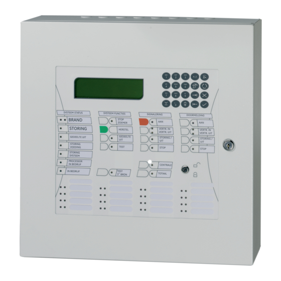
Standard I/O facilities • Rugged loop driver optimised for − EMC/EMI regulations − Operation in worst case conditions of high capacitance and resistance which makes it ideal for retrofit market. • Current loop to drive up to 15 fireman’s panels •... - Page 12 2. P ANEL OPERATION A view of the front of a typical FP2000 Series Fire panel is shown in Figure 1 below. Figure 1: Fire Panel Front View In order to describe the operation of a FP2000 series fire panel, the front panel has been divided into two sections, these being: •...
-
Page 13: Led Indications And Controls
Led indications and controls The LED Indications and controls can further be broken down into: • General indicators • Controls • Sounders • Fire Brigade • Enable/Disable keyswitch • Zone indicators Figure 2: General Indications and Controls General indicators COMMON FIRE Two red LED's indicate that a fire has been detected. - Page 14 COMMON DISABLE A yellow LED indicates that one or more of the following have been disabled: • Devices on the loop • Zone • Sounders • Fire Brigade SUPPLY FAULT A yellow LED will illuminate for: • Mains failure • Battery disconnect or not charging SYSTEM FAULT A yellow LED indicates that a system fault has occurred.
-
Page 15: Controls
Controls SILENCE BUZZER (Keyswitch Enabled or Disabled) The internal panel buzzer is activated for any new condition. The buzzer will be continuous for a fire alarm condition, intermittent for a fault warning and slow intermittent for a condition warning. The buzzer is silenced by pressing the Silence Buzzer Key. The yellow silence buzzer LED will illuminate to indicate that the buzzer has been silenced. -
Page 16: Fire Brigade
SILENCE (Keyswitch Enabled) Depends on operation selected by bits 5 and 6 of DIP switch on HOST PSU board. (*See Appendix B of the FP2000 Installation and Commissioning Manual: LKFP2003). A yellow LED indicates that the sounders have been silenced. Fire brigade SIGNAL (Keyswitch Enabled) Depends on operation selected by bits 5 and 6 of DIP switch on HOST PSU board. -
Page 17: Other
Other PANEL This button is used by global and local repeaters for panel emulation. Emulation mode is activated with a global repeater by pressing the Panel key, then entering the number of the panel to be emulated, and Enter ( To stop emulation, the Panel key is pressed and then "0"... -
Page 18: Lcd And Keypad
Figure 4: 64 Zone Fire and Fault Indication A red, fire LED, flashing indicates the first zone detected, in fire, by the panel. A red LED burning constantly indicates a zone in fire. Note: Only the first zone in fire’s LED will flash. All LEDs indicating a zone in fire can only be cleared by resetting the panel. - Page 19 Move to the next field in the display Move to the previous field in the display Increment Decrement...
-
Page 20: Start-Up Screens
3. LCD S CREEN OPERATION Start-up screens When switching the panel on, the version of software currently in the host chip is displayed. The system also checks for the version of software in the FEP chip and compatibility between these two are checked. If the software are not compatible the message “Incompatible FEP software !”... - Page 21 System Status System Mode Idle Day Mode Powerup Night Mode Scanning Security Zones On Autosetup Security Zones Off Sensor test For example Scanning, Day Mode, Zones On Scanning, Day Mode, Zones Off Scanning, Night Mode, Zones On etc. If the panel is assigned a number, the number is displayed as part of the alarm line: Fire panel Global repeater or master panel Local repeater panel...
-
Page 22: Valid Entries Line
Valid entries line The second line from the bottom displays the valid keypad entries for the displayed menu, as well as messages for the operator. The following table describes these characters and messages and their relation to the keypad: KEYPAD DESCRIPTION MENU DISPLAY... -
Page 23: Status Line
Status line The status line is the third line from the bottom (see highlighted line) and the system status, as summarised in the alarm line, is displayed in full. Note that the system status line is not present in all menus: SYSTEM STATUS Tue 12/12/00 09:17:37 Scanning... -
Page 24: Access To Main Menu
4. P ROGRAMMING MENUS Access to main menu Main Menu obtained from the System Status Screen after entering an access code. If the fire panel is currently displaying alarms, faults, or conditions on the screen, then press to obtain the System Status Screen. SYSTEM STATUS Tue 12/12/00 09:17:37 Scanning... -
Page 25: Main Menu
Main menu (SYSTEM STATUS, , CORRECT CODE, MAIN MENU 1 System 2 Devices 3 Input/Output 4 Events 5 Maintenance 6 Test/Disable 0. .9, <>, Alarms: 0 Faults: 0 Cond.: 0 P: 1 Select number or use and press Return to System Status *See Chapter 3. - Page 26 • Test/Disable - Zones and individual devices can be selectively tested and disabled. Test features include one-man test of zones and soak test of individual devices. The Test and Disable Menus are not directly available from the Main Menu, but are accessed by using the Test and Disable keys on the front panel.
-
Page 27: System Menu
System menu (MAIN MENU, 1, SYSTEM MENU 1 Configuration 2 Access 3 Clear Site Data 4 Set Default 5 Set Times 6 Restart 0. .9, <>, Alarms: 0 Faults: 0 Cond.: 0 P: 1 Return to Main Menu Page 23 Select number or use and press The System Menus are used to configure and display the internal operation of the fire... -
Page 28: Configuration Menu
Configuration menu (SYSTEM MENU, 1, CONFIGURATION MENU 1 Hardware 2 Allocation 3 ID 4 Communication 5 System Setup 6 System Information 0. .9, <>, Alarms: 0 Faults: 0 Cond.: 0 P: 1 Return to System Menu Page 25 Select number or use and press 1 Hardware Page 27... -
Page 29: Hardware Configuration 1
Hardware configuration 1 (CONFIGURATION, 1, HARDWARE Ports: 6 Zones : 255 Loops : 2A Unlocked : 256k Locked RAM : 128k Relays Sup.Rel. Inputs Backpanel: Frontpanel: more Alarms: 0 Faults: 0 Cond.: 0 P: 1 Return to Configuration Menu Page 26 Press [More ] to view Version Page 29... - Page 30 Backpanel and Frontpanel Input and Output Equipped - The FP2000 contains, as standard, relays and input ports. The back panel refers to the boards plugged into the FEP section in the base of the fire panel. The front panel refers to the boards plugged into the HOST section in the door of the fire panel.
-
Page 31: Version
Version (CONFIGURATION 1, VERSION Product :FP2000 Host :6.10 2000-00 09.11.00 7196H :6.10 0000-00 20.11.00 796EH more <>, Alarms: 0 Faults: 0 Cond.: 0 P: 1 Return to Configuration Menu Page 26 Press [More ] to view Site Version Page 30 This menu is used to display the version number and the compilation date of the installed HOST and FEP software as well as their checksums in hex format. -
Page 32: Site Version
Site Version (CONFIGURATION 1, SITE VERSION Vers. Date Time Check Site 00020 24.11.00 09:20:44 10683 Block 00001 24.11.00 08:51:04 30394 more 0. .9, <>, Alarms: 0 Faults: 0 Cond.: 0 P: 1 Return to Configuration Menu Page 26 Press [More ] to view Hardware Configuration 2 Page 31 This menu displays the self-diagnostic data of the FP2000 system. -
Page 33: Hardware Configuration 2
Hardware configuration 2 (CONFIGURATION 1, HARDWARE CONFIGURATION Host :DEN ........ -
Page 34: Board Information
Board information (HARDWARE CONFIGURATION 2, BOARD INFORMATION Addr. Sup1:passive Inp5:passive Sup2:passive Inp6:passive Type :VDS Sup3:passive Inp7:passive Sup4:passive Inp8:passive Alarms: 0 Faults: 0 Cond.: 0 P: 1 Return to Hardware Configuration 2 Page 31 This includes: • Board description • Actual board address The board address is used in certain I/O programming The board description and address in a two loop, 16 zone FP2000 is given below. -
Page 35: Memory Allocation 1
Memory allocation 1 (CONFIGURATION, 2, MEMORY ALLOCATION Free unlocked :175238 Free locked :84042 Logic :600 Input Text Inputs :200 Output Text Outputs :200 Zone Text Events :999 Area Text more 0. .9, <>, Alarms: 0 Faults: 0 Cond.: 0 P: 1 Return to Configuration Menu Page 26 Select item to be changed... -
Page 36: Memory Allocation 2
Memory allocation 2 (CONFIGURATION, 2, MEMORY ALLOCATION Loop Devices Text Loop Devices Text more Alarms: 0 Faults: 0 Cond.: 0 P: 1 Return to Configuration Menu Page 26 Press [More ] to view Memory Allocation 1 Page 33 The amount of RAM memory allocated to field devices on the loops is viewed with this screen. -
Page 37: Panel Id
Panel ID (CONFIGURATION, 3, IDENTIFICATION Change of Node ID Clears Eventbuffer! Node : 1 / 0 Max. Config.:15/15 Panel 0. . 9, Alarms: 0 Faults: 0 Cond.: 0 P: 1 Return to Configuration Menu Page 26 Select item to be changed or 0..9 change data in item (Unlock memory!) Confirm change Return to Configuration Menu... - Page 38 The field "Panel" confirms the fire panel number. The panel ID is also shown on line 8 of the display: P:p. For global repeaters the word "Panel" becomes "G-Repeater" and line 8 displays G:r. For local repeaters the display is "repeater" and L:p/r is displayed on line 8. The field Max.
-
Page 39: Communication Menu
Communication menu (CONFIGURATION, 4, COMMUNICATION MENU 1 Port Setup 1 Network 3 Modem 4 CL Devices 5 LON Devices 0. . 9, <>, Alarms: 0 Faults: 0 Cond.: 0 P: 1 Return to Configuration Menu Page 26 Select number or use and press 1 Port Setup Page 38... -
Page 40: Port Setup
Port setup (COMMUNICATION, 1, PORT SETUP Port :INT Baudrate :9600 Allocation :FEP Protocol :8, 1, n <>, Alarms: 0 Faults: 0 Cond.: 0 P: 1 Return to Communication Menu Page 37 Select item to be changed Change data in the item (Unlock memory!) Confirm change This menu is used to set the function and, if applicable, the data rate (Baudrate) of the physical communication ports. - Page 41 Rp.Pri Set the selected port as a report printer. The report printer port is used to manually sent report to a device such as a printer or laptop computer. It is primarily used for selected printing of the event buffer, test reports and such.
- Page 42 2400 4800 Default for CMSI 9600 Default 19200 38400 Select the mode of operation for the ARCNET ports: Only for CE-FP-344-x Dual Bus Ring Half Duplex Ring Half Duplex (Master) Ring Full Duplex The protocol of the serial ports is fixed: Eight data bits, one stop bit, and no parity. For the CMSI port it is seven data bits, one stop bit and even parity.
-
Page 43: Network Menu
Network menu (COMMUNICATION, 2, NETWORK MENU 1 Panels 2 L-Repeaters 3 G-Repeaters 0. . 9, <>, Alarms: 0 Faults: 0 Cond.: 0 P: 1 Return to Communication Menu Page 37 Select number or use and press 1 Panels Page 42 Define other fire panels on the network that will communicate with this fire panel. -
Page 44: Panels
Panels (NETWORK, 1, PANELS Panel No. Status :dis Start Zone End Zone :255 0. . 9, <>, Alarms: 0 Faults: 0 Cond.: 0 P: 1 Return to Network Menu Page 41 or 0..9 to select panel number Move to status field Toggle dis/NET1 check/NET2 check/ NET1 no check/NET2 no check (Unlock memory!) Confirm entry... -
Page 45: Local Repeaters
Local repeaters (NETWORK, 2, LOCAL REPEATERS L-Repeater No. Status :dis <>, Alarms: 0 Faults: 1 Cond.: 0 P: 1 Return to Network Menu Page 41 or 0..9 to select repeater number Move to status field Toggle dis/NET1 check/NET2 check/NET1 no check/NET2 no check (Unlock memory!) Confirm entry The local repeater that will communicate with this FP2000 panel on the network, must be... -
Page 46: Global Repeaters
Global repeaters (NETWORK, 3, GLOBAL REPEATERS G-Repeater No. Status :dis <>, Alarms: 0 Faults: 1 Cond.: 0 P: 1 Return to Network Menu Page 41 or 0..9 to select master number Move to status field Toggle NET1 check/NET2 check/NET1 no check/NET2 no check (Unlock memory!) Confirm entry The global repeaters and global zone repeaters... -
Page 47: Modem Menu
Modem menu (COMMUNICATION, 3, MODEM MENU 1 Alarm Report 2 Maintenance 3 Setup 0. . 9, <>, Alarms: 0 Faults: 1 Cond.: 0 P: 1 Return to Communication Menu Page 37 Select number or use and press 1 Alarm Report Page 46 Set up the conditions for alarm reporting and the destination telephone numbers. -
Page 48: Modem Alarm Report 1
Modem alarm report 1 (MODEM, 1, MODEM ALARM REPORT Tel. No. Fire Fault Cond. Disc. local local local more Numeric, A. . z, ^V, <>, Alarms: 0 Faults: 1 Cond.: 0 P: 1 Return to Modem Menu Page 45 Select field to be changed To change selection (Unlock memory!) Confirm entry For telephone numbers:... -
Page 49: Modem Alarm Report 2
Modem alarm report 2 (MODEM ALARM REPORT 1, MODEM ALARM REPORT Fire Delay :60 s Report :dis Fault Delay :60 s Test Call :dis Cond. Delay :60 s Test Line :dis more 0. . 9, <>, Alarms: 0 Faults: 1 Cond.: 0 P: 1 Return to Modem Menu... -
Page 50: Modem Maintenance
Modem maintenance (MODEM, 2, MODEM MAINTENANCE Maintenance :dis Dial back :dis <>, Alarms: 0 Faults: 1 Cond.: 0 P: 1 Return to Modem Menu Page 45 To change selection (Unlock memory!) Confirm entry Remote maintenance via the modem can be disabled while the modem interface is operational. -
Page 51: Modem Setup 1
Modem setup 1 (MODEM, 3, MODEM SETUP Wait for Connection :60 s Pause between Calls :60 s Max. dialling attempts more 0. . 9, <>, Alarms: 0 Faults: 1 Cond.: 0 P: 1 Return to Modem Menu Page 45 Select field to be changed To change selection (Unlock memory!) Use 0..9 or To change field values... -
Page 52: Modem Setup 2
Modem setup 2 (MODEM SETUP 1, MODEM SETUP Init :AT&FØMØL1\NØ\JØ\Q3&QØ SØ=1&WØ Dial :ATDWT Escape :+++ more Numeric, A. . z, ^V, <>, Alarms: 0 Faults: 0 Cond.: 0 P: 1 Return to Modem Menu Page 45 Select field to be changed to toggle between alpha and numeric text when necessary and press the required button Press... -
Page 53: Modem Setup 3
Modem setup 3 (MODEM SETUP 2, MODEM SETUP Hangup :ATHØ Test :ATDWT, more Numeric, A. . z, ^V, <>, Alarms: 0 Faults: 1 Cond.: 0 P: 1 Return to Modem Menu Page 45 Select field to be changed to toggle between alpha and numeric text when necessary and press the required button Press to confirm (Unlock memory!) -
Page 54: Cl Devices
CL devices (COMMUNICATION MENU, 4, CL DEVICES Panel Inputs Mode :dis Outputs 0. . 9, <>, Alarms: 0 Faults: 1 Cond.: 0 P: 1 Return to Communication Menu Page 37 Select field to be changed Enter number 0..9 or to change panel field Select mode Confirm entry (Unlock memory!) Current Loop Devices:... -
Page 55: Lon Devices
LON Devices (COMMUNICATION MENU, 5, LON DEVICES SETUP Add Rem Srv All CLr Node : Stat: en FldSeq. Type : FBP700 FldType None 001 Ver:1.02 FldID 000 Ver: 0.00 00A008781900 FldNID 000000000000 LOC : 00/00/00 0. . 9, <>, Alarms: 0 Faults: 1 Cond.: 0 P: 1... - Page 56 FRL700: Local Repeater RB700: FP700 Relay card NA700: FP700 Network Amplifier VdS700: FP700 Sounder card FBP700-F: French Repeater Panel If a FP700 module is configured on the LON port, the location (LOC) of the board can be saved here to make future reference easier. LOC: 04/02/03 04 - Refers to the enclosure the module is located...
-
Page 57: Step-By-Step Lon Device Installation Walkthru
Step-by-step LON device installation walkthru Any LON device or -module can be connected to a FP2000 firepanel via a LON2000 module. Here is a step-by-step installation example for the FBP700: 1. Connect the FBP700 to the FP2000 (24V to supply, communication to LON2000) 2. -
Page 58: System Setup
: continuous FSK Heater : off : none Language : English Operation : EN Protocol : Aritech 900 <>, Alarms: 0 Faults: 0 Cond.: 0 P: 1 Return to Configuration Menu Page 26 Select field to be changed Select mode... - Page 59 range of products. The FP2xxx range of products language is set by the dip switch situated on the host power supply (*See Appendix A of the FP2000 Installation and Commissioning Manual for dip switch settings as well as modes of operation). The switch is read at restart, and cannot be changed during operation.
-
Page 60: System Information
System information (SYSTEM MENU, 6, SYSTEM INFORMATION 1 Allocation 2 Panels 3 L-Repeaters 4 G-Repeaters 5 System 6 Stack 7 SpecialCharacters 8 Text Debugging more 0. .9, <>, Alarms: 0 Faults: 0 Cond.: 0 P: 1 Return to Configuration Menu Page 26 Select number or use and press... -
Page 61: Access Menu
Access menu (SYSTEM MENU, 2, ACCESS MENU 1 Access Codes 2 Field Access 0. . 9, <>, Alarms: 0 Faults: 1 Cond.: 0 P: 1 Return to System Menu Page 25 Select number or use and press 1 Access Codes Page 60 Examine or change user access codes and the access level of any these codes. -
Page 62: Access Codes
Access codes (ACCESS MENU, 1, ACCESS CODES Access No. Access Code Access Level 0. . 9, <>, Alarms: 0 Faults: 1 Cond.: 0 P: 1 Return to Access Menu Page 59 Select item to be changed or 0..9 change data in item (Unlock memory!) Confirm entry *See also Page 61 Six access codes are allowed in order to use the menu screens viz. -
Page 63: Field Access
Field access (ACCESS MENU, 2, FIELD ACCESS Field number Access Level 0. . 9, <>, Alarms: 0 Faults: 1 Cond.: 0 P: 1 Return to Access Menu Page 59 Select item to be changed 0..9 change data in item (Unlock memory!) Confirm entry *See also Page 60 Each menu can be assigned an access level: 1-Low level;... -
Page 64: Clear Site Data 1
Clear site data 1 (SYSTEM MENU, 3, CLEAR SITE DATA 1 Devices 2 Zones 3 Areas 4 Inputs 5 Outputs 6 System 7 Loops 8 Logic Table more 0. . 9, <>, Alarms: 0 Faults: 1 Cond.: 0 P: 1 Select number or use and press (Unlock memory!) - Page 65 5 Outputs – All outputs are set to: Type: None 6 System Panel ID: Ø/ Ø Port: set to FEP; Baudrate 9600 set to CL Device; Baudrate 600 SER1 - set to Setup; Baudrate 9600 SER2 - set to None; Baudrate 9600 Other ports - function: None Network:...
-
Page 66: Clear Site Data 2
Clear site data 2 (CLEAR SITE DATA 1, CLEAR SITE DATA 1 Modem 2 CL Devices 3 LON Devices 4 All more 0. . 9, <>, Alarms: 0 Faults: 1 Cond.: 0 P: 1 Select number or use and press (Unlock memory!) When prompted for confirmation: For Devices select loop number or use... -
Page 67: Set Default
Set default (SYSTEM MENU, 4, SET DEFAULT 1 Devices 2 Zones 3 Area 4 System 5 Loops 6 Configuration 7 Logic table 8 Modem 0. . 9, <>, Alarms: 0 Faults: 1 Cond.: 0 P: 1 Select number or use and press (Unlock memory!) When prompted for confirmation:... - Page 68 2 Zones The total number of zones equipped on the FP2000 fire panel are proportioned amongst the total number of devices that can be addressed by the fire panel. E.g.: 16 zone 2 loop fire panel maximum number of devices = 2 x 128 = 256 zone distribution = 256 / 16 = 16 Loop 1/1 Loop 1/16 is assigned zone 1...
- Page 69 8 Modem: Select Modem Manufacturer Fire Delay Fault Delay Condition Delay Wait for connection = Pause between calls = Max. dial-in attempts = Init. string: None: US Robotics: AT& F1MØL1&MØ&KØ SO=1&WØ Fast Link: AT&FØMØL1\NØ\JØ\Q3&QØ%CØ SO=1&WØ Datasystems: AT&FØMØL1\NØ\JØ\Q3&QØ%CØ SO=1&WØ Bausch: AT&F1M1L1\NØ&QØ%CØ SO=1&WØ...
-
Page 70: Set Times Menu
Set times menu (SYSTEM MENU, 5, SET TIMES MENU 1 Date & Time 2 Output Delays 3 Fbrig Delay off 4 Sounder Delay off 5 Zones off 6 Zones on 7 Day Mode 8 Night Mode 0. . 9, <>, Alarms: 0 Faults: 1 Cond.: 0... -
Page 71: Set Date And Time
Set date and time (SET TIMES MENU, 1, SET DATE AND TIME Thu 07/12/00 10:39:52 Current Date :07/12/00 (dd/mm/yy) Current Time :10:39:52 (hh/mm/ss) Summer Time :00/00 00/00 (dd/mm) Advance 0. . 9, <>, Alarms: 0 Faults: 1 Cond.: 0 P: 1 Return to Set Times Menu Page 68 Select item to be changed... -
Page 72: Output Delays
Output delays (SET TIMES MENU, 2, OUTPUT DELAYS Sounder :120 s Delay :off Fbrig :120 s Delay :off Fltrt :0 s Delay :off Fprot :0 s Delay :off 0. . 9, <>, Alarms: 0 Faults: 1 Cond.: 0 P: 1 Return to Set Times Menu Page 68 Select item to be changed... -
Page 73: Fire Brigade Delay Off Times
Fire brigade delay off times (SET TIMES MENU, 3, FBRIG DELAY OFF Thu 07/12/00 10:39:52 Monday :18:00 Friday :18:00 Tuesday :18:00 Saturday :18:00 Wednesday :18:00 Sunday :18:00 Thursday :18:00 0. . 9, <>, Alarms: 0 Faults: 0 Cond.: 0 P: 1 Return to Set Times Menu Page 68 Select item to be changed... -
Page 74: Sounder Delay Off Times
Sounder delay off times (SET TIMES MENU, 4, SOUNDER DELAY OFF Thu 07/12/00 10:39:52 Monday :18:00 Friday :18:00 Tuesday :18:00 Saturday :18:00 Wednesday :18:00 Sunday :18:00 Thursday :18:00 :none 0. . 9, <>, Alarms: 0 Faults: 0 Cond.: 0 P: 1 Return to Set Times Menu Page 68 Select item to be changed... -
Page 75: Zone Off Times
Zone off times (SET TIMES MENU, 5, ZONES OFF Thu 07/12/00 10:39:52 Monday :08:00 Friday :08:00 Tuesday :08:00 Saturday :08:00 Wednesday :08:00 Sunday :08:00 Thursday :08:00 0. . 9, <>, Alarms: 0 Faults: 0 Cond.: 0 P: 1 Return to Set Times Menu Page 68 Select item to be changed or 0..9 change data in item (Unlock memory!) -
Page 76: Zone On Times
Zone on times (SET TIMES MENU, 6, ZONES ON Fri 07/12/00 10:39:52 Monday :18:00 Friday :18:00 Tuesday :18:00 Saturday :18:00 Wednesday :18:00 Sunday :18:00 Thursday :18:00 :none 0. . 9, <>, Alarms: 0 Faults: 0 Cond.: 0 P: 1 Return to Set Times Menu Page 68 Select item to be changed or 0..9 change data in item (Unlock memory!) -
Page 77: Day Mode Times
Day mode times (SET TIMES MENU, 7, DAY MODE Thu 07/12/00 10:39:52 Monday :08:00 Friday :08:00 Tuesday :08:00 Saturday :08:00 Wednesday :08:00 Sunday :08:00 Thursday :08:00 :none 0. . 9, <>, Alarms: 0 Faults: 0 Cond.: 0 P: 1 Return to Set Times Menu Page 68 Select item to be changed or 0..9 change data in item (Unlock memory!) -
Page 78: Night Mode Times
Night mode times (SET TIMES MENU, 8, NIGHT MODE Thu 07/12/00 10:39:52 Monday :18:00 Friday :18:00 Tuesday :18:00 Saturday :18:00 Wednesday :18:00 Sunday :18:00 Thursday :18:00 0. . 9, <>, Alarms: 0 Faults: 0 Cond.: 0 P: 1 Return to Set Times Menu Page 68 Select item to be changed or 0..9 change data in item (Unlock memory!) -
Page 79: Restart Menu
Restart menu (SYSTEM MENU, 6, RESTART Restart Panel <>, Alarms: 0 Faults: 0 Cond.: 0 P: 1 Returns to System Menu Page 25 To select ENABLE Confirm (Unlock memory!) Restarting the panel as if it had been switched off and then on. -
Page 80: Device Menu
Device menu (MAIN MENU, 2, DEVICE MENU 1 Setup 2 Zones 3 Areas 4 Zone Graphics 5 Device Graphics 6 Zone Range 0. . 9, <>, Alarms: 0 Faults: 0 Cond.: 0 P: 1 Enter number or use and press Return to Main Menu Page 23 1 Setup... -
Page 81: General Setup And View (All Types)
General setup and view (all types) (DEVICE MENU, 1, SCREEN 1 DEVICE SETUP Address :1/4 Status State :NML Zone Type :OPT Value Day Lvl PreLvl AlarmLvl :110 more <>, Alarms: 0 Faults: 0 Cond.: 0 P: 1 Return to Device Menu Page 78 Select field to be changed Enter number 0..9 or... - Page 82 The parameters set by the user are: • Address: loop/address - Select the device to be viewed. • Status: enable/disable/soak - This determines if the device is currently active or not. When a device is in "soak", no alarm condition or outputs will be triggered when the device comes into alarm —...
- Page 83 Depending on the communication protocol, not all of these types are available. Aritech Series 900 only See the Gas Control Unit Manual (GC900 Operating Manual) for further details Aritech Series 2000 only • Day Level: 1 — 5 - Default 3 (Smoke and heat detectors only) The fire alarm and precondition threshold for smoke and heat detectors is set.
- Page 84 • State: - The alarm or fault state of the device can be viewed. The state is latched when it occurs and is only cleared upon reset. The state that a device can be is: normal COMM - communication fault fault disabled wrong type...
-
Page 85: Smoke And Heat Detectors
Level, Page 81). The value of a smoke detector is related to the smoke obscuration (measured in %/meter) for ionisation and optical detectors, and °C for heat detectors. The protocol being used to communicate to this device is also displayed. They are: Aritech Series 2000 Aritech Series 990... - Page 86 Aritech Series 900 Aritech Series 950 TestVal: The value returned during Device Self-Test. A value that is less than the alarm threshold will result in a maintenance condition. FldAvg: The average value of the device measured over a 20-minute period.
-
Page 87: Manual Call Point
Page 80 for field type descriptions. FldDt: The value returned by a manual call point is one of three: Fault Normal Fire Alarm The protocol being used to communicate to this device is also displayed. They are: ARI Aritech Series 2000... - Page 88 Aritech Series 900 Aritech Series 950 TestVal: The value returned during Device Self-Test. A value that is less than the alarm threshold will result in a maintenance condition. Alarms: The number of fire alarms produced by the device since the last...
-
Page 89: Sounder
Fault Normal The protocol being used to communicate to this device is also displayed. They are: ARI Aritech Series 2000 Aritech Series 900 Aritech Series 950 Mode: The current state of the sounder. The sounder can be in one of... - Page 90 sounder off Warning Pls. sounder operating intermittently Alarm Pls. sounder operating intermittently Alarm cont. the sounder is continuously operating Depending on the communication protocol, this device is not always available.
-
Page 91: Indicating Circuit Controller
Fault Normal The protocol being used to communicate to this device is also displayed. They are: ARI Aritech Series 2000 Aritech Series 900 Aritech Series 950 Mode: The current state of the sounder. The sounder can be in one of... -
Page 92: Monitor Units
ICC off Warning Pls. ICC operating intermittently Alarm Pls. ICC operating intermittently Alarm cont. the ICC is continuously operating Depending on the communications protocol, this device is not always available. Monitor units (DEVICE MENU, 1, SCREEN 2 DEVICE SETUP ClrStat Address :1/7 Status... - Page 93 Fault Normal Fire Alarm The protocol being used to communicate to this device is also displayed. They are: ARI Aritech Series 2000 Aritech Series 900 Aritech Series 950 TestVal: The value returned during Device Self-Test. A value that is less than the alarm threshold will result in a maintenance condition.
-
Page 94: Input/Output Units
Input/output units (DEVICE MENU, 1, SCREEN 2 DEVICE SETUP ClrStat Address :1/6 Status State :NML CommQlt :100% FldType :I/O FldDt Channel Inputs :passive Outputs :off more 0. .9, <>, Alarms: 0 Faults: 0 Cond.: 0 P: 1 Return to Device Menu Page 78 Select field to be changed Enter number 0..9 or... - Page 95 The protocol being used to communicate to this device is also displayed. They are: X90 Aritech Series 900 Aritech Series 950 Channel: The status of the input channels and output channels is shown Inputs: The input status can be Active or Passive, Open or Short.
-
Page 96: Gas Unit I/O (Gcu 1)
Field Type: The device type as seen by the fire panel. *See Page 80 for field type descriptions. FldDt: The value returned depends on the state of Isolation Mode and Gas Discharge. The protocol being used to communicate to this device is also displayed. This is: X90 Aritech Series 900... - Page 97 The screen will also show the status of the gas control unit. Fire 1, Fire 2 Fire zones allocated to the unit by means of I/O programming OFF or ON Isol Isolated key normal or isolated Mode Automatic or manual Normal or discharged Depending on the communication protocol, this device is not always available.
-
Page 98: Zone Menu
Zone menu (DEVICE MENU, 2, ZONE Coincidence I.S. Zone :dis Zone on/off :dis Status Day/Night :dis Mode :normal Sounder Delay :dis Area Fbrig Delay :dis 0. .9, <>, Alarms: 1 Faults: 0 Cond.: 0 P: 1 Return to Device Menu Page 78 Select field to be changed Enter number 0..9 or... - Page 99 • Mode: - A coincidence condition is logged in the event buffer when two or more fire monitoring devices of the zone in alarm. A coincidence condition can also be used as an input for I/O logic switching. When viewing the display alarm screen, the abbreviation "COI"...
- Page 100 • I.S. Zone*: enable/disable - Enables/disables an intrinsically safe zone. (The number of device LED's for this zone is limited to 2). • Coincidence: - Indicates that two or more devices have triggered a fire alarm. 112 Zones are provided for control purposes. Depending on the configuration, 16/64, 32/128, 48/192 or 64/255 zones can be...
-
Page 101: Area Menu
Area menu (DEVICE MENU, 3, AREAS Coincidence Area Adj 2 Status Adj 3 Coincidence unlogged Adj 4 Adj 1 Adj 5 0. .9, <>, Alarms: 1 Faults: 0 Cond.: 0 P: 1 Return to Device Menu Page 78 Select field to be changed Enter number 0..9 or to change data (Unlock memory!) Confirm entry... - Page 102 • Coincidence: logged/unlogged - Area coincidence occurs if two or more zones assigned to the area have a fire alarm. The area coincidence can be used as an input for I/O switching. When viewing this menu, the word COINCIDENCE will flash if the area is in a coincidence state.
-
Page 103: Zone Graphics
Zone graphics (DEVICE MENU, 4, ZONE GRAPHICS Zone Disp :Value more 0. .9, <>, Alarms: 0 Faults: 0 Cond.: 0 P: 1 Return to Device Menu Page 78 Select field to be changed Enter number 0..9 or to change data Confirm entry Press [More ] to view Graphic Screen... -
Page 104: Zone Graphic Screen
Zone graphic screen (ZONE GRAPHICS, more <>, Alarms: 0 Faults: 0 Cond.: 0 P: 1 Return to Device Menu Page 78 Select bar in bar graph Select scale of bar graph Press [More ] to view statistics of selected bar Page 103 Press [More ], [More... -
Page 105: Graphic Device Statistics
Graphic device statistics (ZONE GRAPHIC SCREEN, DEVICE SETUP Address :1/8 Status State :NML CommQlt :100% FldType :OPT FldDt TestVal :225 FldAvg Obsc. :0.6%/m Alarms High 12/01 07:25 Contam. 11/01 14:16 more Alarms: 0 Faults: 0 Cond.: 0 P: 1 Return to Device Menu Page 78 Press [More ] to return to Zone Graphics... -
Page 106: Device Graphics
Device graphics (DEVICE MENU, 5, DEVICE GRAPHICS Addr. :1/1 Time :11/01/9910:24:06 Sample :1/10 s Value Average :0 Disp :Value High TestVal :0 Contam :0% CommQlt more <>, Alarms: 0 Faults: 0 Cond.: 0 P: 1 Return to Device Menu Page 78 Select field to be changed Enter number 0..9 or to change data... - Page 107 • Disp: Select the type of data that must be recorded for the device Value - The current values of the device FldAvg - The average value of the device Test Val - The device test value High - Highest value achieved by the device - Lowest value achieved by the device Contam - % Contamination of the device...
-
Page 108: Device Graphic Screen
Device graphic screen (DEVICE GRAPHICS, more <>, Alarms: 0 Faults: 0 Cond.: 0 P: 1 Return to Device Menu Page 78 Select a time position in the graph Select the scale of the graph Press [More ] to view statistics of the selected device Page 103 Press [More ], [More... -
Page 109: Graphic Device Setup
Graphic device setup (DEVICE GRAPHIC SCREEN, DEVICE SETUP grap Address :1/4 Status State :NML CommQlt :100% FldType :OPT FldDt TestVal :255 FldAvg Obsc. :0.0%/m Alarms High 12/01 08:57 Contam. 12/01 00:05 more Alarms: 0 Faults: 0 Cond.: 0 P: 1 Return to Device Menu Page 78 Press [More... -
Page 110: Zone Range
Zone range (DEVICE MENU, 6, ZONE RANGE Start :1 :255 Changing the zone range will clear all Zone relations ! 0. .9, <>, Alarms: 0 Faults: 0 Cond.: 0 P: 1 Return to Device Menu Page 78 Press [More ] to return to Device Graphics Page 104 Press [More ], [More... -
Page 111: Input/Output
Input/output (MAIN MENU, 3, INPUT/OUTPUT 1 Inputs 2 Outputs 3 Logic 4 CL Devices 5 Timers 6 Markers 0. .9, <>, Alarms: 0 Faults: 0 Cond.: 0 P: 1 Select number or use and press Return to Main Menu Page 23 1 Inputs View and Define System Inputs Common Facilities - All Input Types... - Page 112 4 CL Devices View and define the programming that determines the switching of current loop outputs according to the settings of the current loop devices. Page 148 5 Timers Monitoring of Timer status. Page 150 6 Markers Monitoring of Marker status. Page 151...
-
Page 113: Common Facilities - All Input Types
Common facilities – all input types * See Input Description in the Serial Communication Format Input: number Enter number or use to view/change the existing defined inputs, or create a new input. Each input required for the I/O logic system must be defined by a unique input number. Unused inputs have type None. - Page 114 Mode: passive/active/open/short/active1/abnormal The meaning of the above options is related to the current flow and voltage level of the specific input. A very low current corresponds to "open"; as the current increases it changes to "passive”, and at higher currents it changes to "active2", and then to ”active”.
- Page 115 The procedure for entering text is as follows: to obtain the text line Toggle for alpha or numeric characters 0..9 For alpha characters press key repeatedly until desired upper or lower case character or key is obtained. Advance cursor to next position Mover cursor back one position Confirm end of text input...
-
Page 116: Input Definition - Type General
Input definition – type General (INPUT/OUTPUT, 1, INPUT DEFINITION State :false Input Trig. :latched Type :General Mode :active Fct. :continuous Common Fire Event unlogged 0. .9, <>, Alarms: 0 Faults: 0 Cond.: 0 P: 1 Return to Input/Output Menu Page 109 Place cursor at TYPE Select Type: GENERAL and press (Unlock memory!) - Page 117 External Supply Fault Hardware Fault Sounder Disabled Fire Brigade Disabled Fault Routing Disabled Fire Protection Disabled Soak Test Zone Test Sounder Test Fire Brigade Test Fault Routing Test Fire Protection Test Maintenance BFS Disabled Pre Warning Common Fault/Condition is active (ON) if any Fault/Condition exists. If the originating Fault(s)/Condition(s) is/are latched, the Common Fault/Condition will be latched, if it is unlatched and is cleared before reset, the Common Fault/Condition will be cleared.
-
Page 118: Input Definition - Type Zone
Input definition – type Zone (INPUT/OUTPUT, 1, INPUT DEFINITION State :false Input Trig. :latched Type :Zone Mode :active Zone continuous Fct. :Fire Event unlogged <>, Alarms: 0 Faults: 0 Cond.: 0 P: 1 Return to Input/Output Menu Page 109 Place cursor at TYPE Select Type: ZONE and press (Unlock memory!) Select the Function... -
Page 119: Input Definition - Type Area
Input definition – type Area (INPUT/OUTPUT, 1, INPUT DEFINITION State :false Input Trig. :latched Type :Area Mode :active Area continuous Fct. :Fire Event unlogged 0. .9, <>, Alarms: 0 Faults: 0 Cond.: 0 P: 1 Return to Input/Output Menu Page 109 Place cursor at TYPE Select Type: AREA and press (Unlock memory!) -
Page 120: Input Definition - Type Adjacent Area
Input definition – type Adjacent Area (INPUT/OUTPUT, 1, INPUT DEFINITION State :false Input Trig. :latched Type :Adj. Area Mode :active Area continuous Fct. :Fire Event unlogged 0. .9, <>, Alarms: 0 Faults: 0 Cond.: 0 P: 1 Return to Input/Output Menu Page 109 Place cursor at TYPE Select Type: ADJ AREA and press... -
Page 121: Input Definition - Type Internal
Input definition – type Internal (INPUT/OUTPUT, 1, INPUT DEFINITION State :false Input Trig. :latched Type :Internal Mode :active Board :24:FEP continuous Input Event unlogged 0. .9, <>, Alarms: 0 Faults: 0 Cond.: 0 P: 1 Return to Input/Output Menu Page 109 Place cursor at TYPE Select Type: INTERNAL and press (Unlock memory!) -
Page 122: Input Definition - Type Time
Input definition – type Time (INPUT/OUTPUT, 1, INPUT DEFINITION State :false Input Trig. :latched Type :Time Mode :active Time :03:25 continuous :Every Day Event unlogged <>, Alarms: 0 Faults: 0 Cond.: 0 P: 1 Return to Input/Output Menu Page 109 Place cursor at TYPE Select Type: TIME and press (Unlock memory!) - Page 123 Mode: Passive/Active Continuous/Pulse Event: Unlogged/Logged/Fire/Fault/Condition Text: Allowed * See Input Description in the Serial Communication Format...
-
Page 124: Input Definition - Type Device Input
Input definition – type Device Input (INPUT/OUTPUT, 1, INPUT DEFINITION State :false Input Trig. :latched Type :Device Input Mode :active Addr. :1/1 :1I/O continuous Chan. Event unlogged 0. .9, <>, Alarms: 0 Faults: 0 Cond.: 0 P: 1 Return to Input/Output Menu Page 109 Place cursor at TYPE Select Type: DEVICE INPUT and press... -
Page 125: Input Definition - Type Device
Input definition – type Device (INPUT/OUTPUT, 1, INPUT DEFINITION State :false Input Trig. :latched Type :Device Mode :active Addr. :1/4 :OPT continuous Fct. :Fire Event unlogged <>, Alarms: 0 Faults: 0 Cond.: 0 P: 1 Return to Input/Output Menu Page 109 Place cursor at TYPE Select Type: DEVICE and press (Unlock memory!) -
Page 126: Input Definition - Type Network
Input definition – type Network (INPUT/OUTPUT, 1, INPUT DEFINITION State :false Input Trig. :latched Type :Network Mode :active Node :01/04 continuous Output Event unlogged 0. .9, <>, Alarms: 0 Faults: 0 Cond.: 0 P: 1 Return to Input/Output Menu Page 109 Place cursor at TYPE Select Type: NET and press (Unlock memory!) -
Page 127: Input Definition - Type Action
Input definition – type Action (INPUT/OUTPUT, 1, INPUT DEFINITION State :false Input Trig. :latched Type :Action Mode :active Fct. continuous Day Mode Event unlogged <>, Alarms: 0 Faults: 0 Cond.: 0 P: 1 Return to Input/Output Menu Page 109 Place cursor at TYPE Select Type: ACTION and press (Unlock memory!) Select the Function... -
Page 128: Input Definition - Type Current Loop Device
Input definition – type Current Loop Device (INPUT/OUTPUT, 1, INPUT DEFINITION State :false Input Trig. :latched Type :CL Dev. Mode :active 1 CL Adr continuous Input Event unlogged 0. .9, <>, Alarms: 0 Faults: 0 Cond.: 0 P: 1 Return to Input/Output Menu Page 109 Place cursor at TYPE Select Type: ACTION and press... -
Page 129: Input Definition - Type Date
Input definition – type Date (INPUT/OUTPUT, 1, INPUT DEFINITION State :false Input Trig. :latched Type :Date Mode :active Date :01:01:00 continuous Event unlogged 0. .9, <>, Alarms: 0 Faults: 0 Cond.: 0 P: 1 Return to Input/Output Menu Page 109 Place cursor at TYPE Select Type: ACTION and press (Unlock memory!) -
Page 130: Common Facilities - All Output Types
Common facilities – all output types * See Output Description in the Serial Communication Format Output: number Enter number or use to view/change the existing defined outputs, or create a new output. Each output required for the I/O logic system must be defined by a unique output number. Unused outputs have type None. - Page 131 • Continuous The output device is true/false according to the continuous state of the output as conditioned by latched and unlatched trigger. • Pulse The output device will operate for one second each time the output state is set true. •...
- Page 132 Mover cursor back one position Confirm end of text input...
-
Page 133: Output Definition - Type General
Output definition – type General (INPUT/OUTPUT, 2, OUTPUT DEFINITION State :false Output Trig. :latched Type :General Mode :normal Fct. continuous Common Fire unlogged <>, Alarms: 0 Faults: 0 Cond.: 0 P: 1 Return to Input/Output Menu Page 109 Place cursor at TYPE Select Type: GENERAL and press (Unlock memory!) Select the Function... -
Page 134: Output Definition - Type Zone
Output definition – type Zone (INPUT/OUTPUT, 2, OUTPUT DEFINITION State :false Output Trig. :latched Type :Zone Mode :normal Zone continuous Fct. :Fire MCP unlogged 0. .9, <>, Alarms: 0 Faults: 0 Cond.: 0 P: 1 Return to Input/Output Menu Page 109 Place cursor at TYPE Select Type: ZONE and press (Unlock memory!) -
Page 135: Output Definition - Type Area
Output definition – type Area (INPUT/OUTPUT, 2, OUTPUT DEFINITION State :false Output Trig. :latched Type :Area Mode :normal Area continuous Fct. :Fire unlogged 0. .9, <>, Alarms: 0 Faults: 0 Cond.: 0 P: 1 Return to Input/Output Menu Page 109 Place cursor at TYPE Select Type: AREA and press (Unlock memory!) -
Page 136: Output Definition - Type Internal
Output definition – type Internal (INPUT/OUTPUT, 2, OUTPUT DEFINITION State :false Output Trig. :latched Type :Internal Mode :normal Board :17:VDS continuous Output unlogged More 0. .9, <>, Alarms: 0 Faults: 0 Cond.: 0 P: 1 Return to Input/Output Menu Page 109 Place cursor at TYPE Select Type: INTERNAL and press (Unlock memory!) -
Page 137: Output Definition - Type Device Output
Output definition – type Device Output (INPUT/OUTPUT, 2, OUTPUT DEFINITION State :false Output Trig. :latched Type :Device Output Mode :normal Addr. :1/1 :1I/O continuous Chan. unlogged more 0. .9, <>, Alarms: 0 Faults: 0 Cond.: 0 P: 1 Return to Input/Output Menu Page 109 Place cursor at TYPE Select Type: DEVICE OUTPUT and press... -
Page 138: Output Definition - Type Supervised Internal
Output definition – type Supervised Internal (INPUT/OUTPUT, 2, OUTPUT DEFINITION State :false Output Trig. :latched Type :Sup Internal Mode :normal Board :17:VDS continuous Output unlogged more 0. .9, <>, Alarms: 0 Faults: 0 Cond.: 0 P: 1 Return to Input/Output Menu Page 109 Select Type: SUP INTERNAL and press 0..9 or... -
Page 139: Output Definition - Type Supervised Device Output
Output definition – type Supervised Device Output (INPUT/OUTPUT, 2, OUTPUT DEFINITION State :false Output Trig. :latched Type :Sup DevOutput Mode :normal Addr. :1/1 :ICC continuous unlogged more <>, Alarms: 0 Faults: 0 Cond.: 0 P: 1 Return to Input/Output Menu Page 109 Select Type: SUP DEV OUTPUT and press 0..9 or... -
Page 140: Output Definition - Type Network
Output definition – type Network (INPUT/OUTPUT, 2, OUTPUT DEFINITION State :false Output Trig. :latched Type :Network Mode :normal Node :01/01 continuous Input unlogged 0. .9, <>, Alarms: 0 Faults: 0 Cond.: 0 P: 1 Return to Input/Output Menu Page 109 Select Type: NETWORK and press Use number or 0...9 to select Panel address that the output is sent to... -
Page 141: Output Definition - Type Current Loop Device
Output definition – type Current Loop Device (INPUT/OUTPUT, 2, OUTPUT DEFINITION State :false Output Trig. :latched Type :CL Dev. Mode :normal CL Adr continuous Output unlogged more 0. .9, <>, Alarms: 0 Faults: 0 Cond.: 0 P: 1 Return to Input/Output Menu Page 109 Move to TYPE field Select Type: NETWORK and press... -
Page 142: Output Definition - Type Supervised Current Loop
Output definition – type Supervised Current Loop (INPUT/OUTPUT, 2, OUTPUT DEFINITION State :false Output Trig. :latched Type :Sup CL Dev. Mode :normal Rep. continuous Output unlogged more 0. .9, <>, Alarms: 0 Faults: 0 Cond.: 0 P: 1 Return to Input/Output Menu Page 109 Select Type: SUP CL DEV and press 0..9 or... -
Page 143: Output Definition - Type Event
Output definition – type Event (INPUT/OUTPUT, 2, OUTPUT DEFINITION State :false Output Trig. :latched Type :Event Mode :normal continuous unlogged Numeric A. .z, <>, Alarms: 0 Faults: 0 Cond.: 0 P: 1 Return to Input/Output Menu Page 109 Select Type: EVENT and press Enter text Select Trigger and Event The output, when switched true by logic is logged to the event buffer. -
Page 144: Output Definition - Type Action
Output definition – type Action (INPUT/OUTPUT, 2, OUTPUT DEFINITION State :false Output Trig. :latched Type :Action Mode :normal Fct. continuous Sounder Delay on unlogged more 0. .9, <>, Alarms: 0 Faults: 0 Cond.: 0 P: 1 Return to Input/Output Menu Page 109 Place cursor at TYPE Select Type: ACTION and press... -
Page 145: Output Definition - Link To Equipment
Output definition – link to equipment (INPUT/OUTPUT, OUTPUT DEFINITION Output Link :SND Mode :Zone Zone more <>, Alarms: 0 Faults: 0 Cond.: 0 P: 1 Return to Input/Output Menu Page 109 Select Link: (SND, Fbrig, Fprot, Fltrt, Logic) and press (Unlock memory!) Enter Mode: (Zone/Area) Select Zone or Area Press [More... - Page 146 Example 2 Output: Link: Mode: Zone Zone: This is a zone Sounder Output. In EP mode the output switches ON. SOUND In EN/NEN/Vds mode the output switches ON only if it was silenced before. The output is disabled. DISABLE The output is only switched after the Sounder DELAY ON/OFF Delay has elapsed.
-
Page 147: Logic
Logic (INPUT/OUTPUT, 3, LOGIC TABLE Input Output Input 0. .9, <>, Alarms: 0 Faults: 0 Cond.: 0 P: 1 Return to Input/Output Menu Page 109 Place cursor over field to be changed and press (Unlock memory!) Either: Select the function and press 0..9 or select a number and press Logic sets outputs assigned in the Output Table true or false according to expressions. - Page 148 xx = term/assignment number yy is used for timer assignment only Expressions may contain any number of terms separated by operators, but only up to nested expressions. Each term is separated by either an "(" or operator or operator ")". Assignment can be Output, Marker or Timer.
- Page 149 The simplest logic statement (which is also the default statement) is: Step m ( Input n Step m+1 ) = Output n Output n will be set true or false if Input n is true or false. An example of a multiple term statement not using nesting is: Step ( Input 1 AND Input 2...
-
Page 150: Cl Devices
CL devices (INPUT/OUTPUT, MENU, 4, CL DEVICES Panel Start Mode :dis Zones Common :dis fire fault cond. test Outputs 0. .9, <>, Alarms: 0 Faults: 0 Cond.: 0 P: 1 Return to Input/Output Menu Page 109 Enter number 0..9 or to select Fireman’s panel address Select field to be changed To confirm entry... - Page 151 of the devices assigned to Adr1,2,3. Outputs: The output number where outputs start on the current loop device. If for example 22 devices in total are allocated then fire could start at 1, fault at 23 and condition at 45. Note that allocation could overlap or gaps could be left between allocations.
-
Page 152: Timers
Timers (INPUT/OUTPUT, MENU, 5, TIMER Timer Time Status :passive 0. .9, <>, Alarms: 0 Faults: 0 Cond.: 0 P: 1 Return to Input/Output Menu Page 109 Enter number 0..250 or to select appropriate timer To confirm entry... -
Page 153: Markers
Markers (INPUT/OUTPUT, MENU, 6, MARKERS Marker Status :false 0. .9, <>, Alarms: 0 Faults: 0 Cond.: 0 P: 1 Return to Input/Output Menu Page 109 Enter number 0..250 or to select appropriate marker To confirm entry... -
Page 154: Event Menu
Event menu (MAIN MENU, 4, EVENT MENU 1 Display Events 2 Clear Events 3 Clear All Events 0. .9, <>, Alarms: 0 Faults: 0 Cond.: 0 P: 1 Enter number or use and press Return to Main Menu Page 23 1 Display Events Page 153 Selectively display or print the event buffer to the specified device. -
Page 155: Display Events
Display events (EVENT MENU, 1, DISPLAY EVENTS Execute Destination :LCD Event Type :All Latest Events :999 After :07/12/00 08:05 <>, Alarms: 0 Faults: 0 Cond.: 0 P: 1 Return to Event Menu Page 152 Select item to be altered or 0..9 enter data Confirm entry After setting up data, use to place cursor over "EXECUTE". - Page 156 • Event Type: All types Soak Area Zone Device General Output Input Action Loop Input and Output The number of events to be displayed is controlled by "Latest Events" after the specified date and time.
-
Page 157: Clear Event Menu
Clear event menu (EVENT MENU, 2, EVENT MENU Clear Events <>, Alarms: 0 Faults: 0 Cond.: 0 P: 1 Return to Event Menu Page 152 toggle YES/NO Confirm entry The event buffer is cleared. The event buffer may only be cleared if the system is in a normal state. -
Page 158: Clear All Events Menu
Clear all events menu (EVENT MENU, 3, EVENT MENU Clear All Events <>, Alarms: 0 Faults: 0 Cond.: 0 P: 1 Return to Event Menu Page 152 toggle YES/NO Confirm entry This function is normally used on a Global Repeater. The event buffer of all the panels connected to the global repeater is cleared. -
Page 159: Maintenance Menu
Maintenance menu (MAIN MENU, 5, MAINTENANCE MENU 1 Reports 2 Clr. Dev. Stat. 3 Hardware Test 4 Maintenance Times 5 Options 6 Loop Test 7 Fast Compensation 0. .9, <>, Alarms: 0 Faults: 0 Cond.: 0 P: 1 Enter number or use and press Return to Main Menu Page 23... -
Page 160: Maintenance Report Menu
Maintenance report menu (MAINTENANCE MENU, 1, MAINTENANCE REPORT MENU 1 Device Values 2 Maintenance Dev. 0. .9, <>, Alarms: 0 Faults: 0 Cond.: 0 P: 1 Enter number or use and press To return to Maintenance Menu Page 157 1 Device Values Page 159 Report the device statistics 2 Maintenance Device... -
Page 161: Device Values
Device values (MAINTENANCE REPORT MENU, 2, DEVICE VALUES Destination :LCD <>, Alarms: 0 Faults: 0 Cond.: 0 P: 1 Return to Maintenance Report Menu Page 159 Select the report destination Confirm entry The statistics of the devices on the loop are reported to the selected destinations. LCD Screen Report printer Event printer... -
Page 162: Device Values [Lcd]
Device values [LCD] (DEVICE VALUES, LCD, DEVICE VALUES Zone:1 12/01/99 11:10 Addr Type Max Tst Comp Obsc TEMP 56 0. .9, <>, Alarms: 0 Faults: 0 Cond.: 0 P: 1 Return to Maintenance Report Menu Page 158 Select zone/address Zone selected: Enter number 0..9, or use to select zone... -
Page 163: Maintenance Device
Maintenance device (MAINTENANCE REPORT MENU, 2, MAINTENANCE DEVICE 12/01/99 11:17 Addr Zone Type Cause Comms Fault <>, Alarms: 0 Faults: 0 Cond.: 0 P: 1 Return to Maintenance Report Menu Page 158 Select the report destination Confirm entry A list of loop devices that have a maintenance condition is produced to the destination- reporting device. -
Page 164: Clear Device Statistics
Clear device statistics (MAINTENANCE MENU, 2, CLEAR DEVICE STATISTICS Enter Zone Nr. (0 for all) 0. .9, <>, Alarms: 0 Faults: 0 Cond.: 0 P: 1 Return to Maintenance Menu Page 157 Enter 0..9 or to select zone. 0 selects all zones Confirm entry *See Device Statistics, Page 83 To clear an individual device, see Page 83... -
Page 165: Hardware Test
Hardware test (MAINTENANCE MENU, 3, The FP2000 performs system tests once per hour. These tests check the memory integrity of the host CPU system including the locked site data memory, as well as the FEP memory system. Invoking the hardware test from the maintenance menu causes a system test to be immediately performed. -
Page 166: Maintenance Times Menu
Maintenance times menu (MAINTENANCE MENU, 4, REPORT TIMES Fri 12/01/99 11:24:29 Next Date :01.01.94 Monday :09:00 Friday :09:00 Tuesday :09:00 Saturday :09:00 Wednesday :09:00 Sunday :09:00 Thursday :09:00 Report :yes 0. .9, <>, Alarms: 0 Faults: 0 Cond.: 0 P: 1 Return to Maintenance Menu Page 157 Select item to be changed... -
Page 167: Options Menu
Options menu (MAINTENANCE MENU, 5, OPTIONS 1 Language 2 Operation 3 Protocol 0. .9, <>, Alarms: 0 Faults: 0 Cond.: 0 P: 1 Enter number or use and press Return to Maintenance Menu Page 157 1 Language Page 166 View the language of operation and temporarily change this language. 2 Operation Page 167 View the operation mode and temporarily change this operation. -
Page 168: Language Menu
Language menu (OPTIONS, 1, LANGUAGE Language :English Temp. Language :English <>, Alarms: 0 Faults: 0 Cond.: 0 P: 1 Return to the Options Menu Page 165 Select temporary language Confirm entry The language used by the FP2000 is displayed. This language is set by the dip switch situated on the host power supply (*See Appendix A of the FP2000 Installation and Commissioning Manual). -
Page 169: Operation Menu
Operation menu (OPTIONS, 2, OPERATION Operation Temp. Operation :Demo <>, Alarms: 0 Faults: 0 Cond.: 0 P: 1 Return to Options Menu Page 165 Select the temporary operation Confirm entry The operating options of the FP2000 is set by means of the dip switch situated on the host power supply (*See Appendix A of the FP2000 Installation and Commissioning Manual). -
Page 170: Device Protocol
(*See Appendix A of the FP2000 Installation and Commissioning Manual) The Aritech 2000 protocol has a second line indicating a working mode; please refer to the appropriate Detector Installation Manual. The working mode can be on/off/blinking, relating to the 7-segment display on some Aritech Series 2000 detector models. -
Page 171: Loop Test 1
Loop test 1 (MAINTENANCE MENU, 6, LOOP TEST Loop Test :General Loop Test Start Test <>, Alarms: 0 Faults: 1 Cond.: 0 P: 1 Return to Maintenance Menu Page 157 Move to required field Select test to be performed Confirm entry Loop test 2 (MAINTENANCE MENU, 6, LOOP TEST... -
Page 172: Loop Test 1 - Parameter Screen 1
• Overloads Loop test 1 – parameter screen 1 (LOOP TEST 1, START TEST, When selecting "START TEST", loop and device parameters will be displayed on the screen. LOOP TEST : General Loop Test Ovld Ovld 1 15 15 Alarms: 0 Faults: 1 Cond.: 0 P: 1... -
Page 173: Loop Test 2 - Parameter Screen 2
Loop test 2 – parameter screen 2 (LOOP TEST 2, START TEST, For "SINGLE" device test, the display will be as follows: LOOP TEST :Single Device on A Side L Val Typ L Val Typ St Ck Alarms: 0 Faults: 0 Cond.: 0 P: 1 Loop number... -
Page 174: Loop Test 3 - Parameter Screen 1
Loop test 3 – parameter screen 1 (LOOP TEST 3, START TEST, For controlling power supply to the loops, the display will be as follows: LOOP TEST Loop Test Power on A side Loop Start Test < >, Alarms: 0 Faults: 0 Cond.: 0 P: 1... -
Page 175: Fast Compensation
Fast Compensation (MAINTENANCE MENU, 7, Returns Automatically to Maintenance Menu Page 157 This function will allow the panel to use a fast compensation algorithm to compensate quickly according to the current analogue values of the smoke detectors. It may be particularly useful in the event of clearing all device statistics when there may already be devices that are highly compensated. -
Page 176: Main Menu
Main menu (MAIN MENU, 6, MAIN MENU 1 System 2 Devices 3 Input/Output 4 Events 5 Maintenance 6 Test/Disable Use dedicated Test and Disable Keys Alarms: 0 Faults: 0 Cond.: 0 P: 1 Selecting OPTION 6 (Test/Disable) on the Main Menu will display the message "Use dedicated Test and Disable Keys". -
Page 177: Test Menu
Test menu Push front panel TEST button TEST MENU 1 Zone Test 2 Test Devices 3 Output test 4 Lamptest 5 Alarm Count 6 User Log 0. .9, <>, Alarms: 0 Faults: 0 Cond.: 0 P: 1 Select number or use and press Return to menu that was displayed prior to Test being pushed. -
Page 178: Zone Test Menu
Zone test menu (TEST MENU, 1, ZONE TEST MENU 1 Zone Test 2 Test Report 3 Clr. Testresults 4 Exception Report 0. .9, <>, Alarms: 0 Faults: 0 Cond.: 0 P: 1 Select number or use and press Return to Test Menu Page 175 1 Zone Test Page 177... -
Page 179: Zone Test
Zone test (ZONE TEST MENU, 1, ZONE TEST Start: dd/mm hh:mm Zone 12/01 11:29 Zone 12/01 11:29 Zone 00/00 00:00 Zone 00/00 00:00 0. .9, <>, Alarms: 0 Faults: 1 Cond.: 0 P: 1 Return to Zone Test Menu Page 176 Select a new zone entry to start test or to cancel test or 0..9 to select the zone number Confirm entry... -
Page 180: Full Test Report
Full test report (ZONE TEST MENU, 2, FULL TEST REPORT Destination :LCD 0. .9, <>, Alarms: 0 Faults: 1 Cond.: 0 P: 1 Return to Zone Test Menu Page 176 Select the report destination Confirm entry The full test report is displayed/printed to the selected device. The test report shows all testable devices (see Page 176) and the pass/fail result of the device. -
Page 181: Test Report [Lcd]
Test report [LCD] (FULL TEST REPORT, LCD, FULL TEST REPORT 12/01/99 11:31 Zone :12/01 11:29 :12/01 11:30 Addr Type Fire on Fire off TEMP 0. .9, <>, Alarms: 0 Faults: 0 Cond.: 0 P: 1 Return to Zone Test Menu Page 176 Select zone/Addr. -
Page 182: Clear Test Results
Clear test results (ZONE TEST MENU, 3, CLEAR TEST RESULTS Enter Zone Nr. (0 for all) 0. .9, <>, Alarms: 0 Faults: 0 Cond.: 0 P: 1 Return to Zone Test Menu Page 176 Enter 0..9 or use to select the zone (0 = all zones) Confirm entry The test report of the selected zone(s) is cleared. -
Page 183: Exception Test Report
Exception test report (ZONE TEST MENU, 4, EXCEPTION TEST REPORT Destination :LCD <>, Alarms: 0 Faults: 1 Cond.: 0 P: 1 Return to Zone Test Menu Page 176 Select the report destination Confirm entry The exception report is displayed/printed to the selected device. The test report shows all that have either not been tested or failed the test. -
Page 184: Exception Test Report [Lcd]
Exception test report [LCD] (EXCEPTION TEST REPORT, LCD, EXCEPTION TEST REPORT 12/01/99 11:31 Zone :00/00 00:00 :00/00 00:00 Addr Type Fire on Fire off TEMP 0. .9, <>, Alarms: 0 Faults: 0 Cond.: 0 P: 1 The exception test report is listed in order of zone and loop/address. The cursor will toggle between zone and address. -
Page 185: Test Devices
Test devices (TEST MENU, 2, TEST MENU Start Device Test :yes <>, Alarms: 0 Faults: 0 Cond.: 0 P: 1 Return to Test Menu Page 175 Toggle YES/NO for test Confirm entry The devices on the loop are tested and the test values are updated. The loop driver is switched to the opposite side of the loop and polling occurs from that side. -
Page 186: Output Test
Output test (TEST MENU, 3, OUTPUT TEST Sounder :off Fbrig :off Fltrt :off Fprot :off <>, Alarms: 0 Faults: 1 Cond.: 0 P: 1 Return to Test Menu Page 184 Select Sounder Test/FB Test Toggle ON/OFF Confirm entry The Sounder, Fire Brigade, Fault Routing and Fire Protection, outputs can be tested. The tested outputs are pulsed at once per second. -
Page 187: Lamp Test
Lamp test TEST MENU, 4, The LED lamps of the front panel are illuminated. The lamps are illuminated in blocks where each block is tested for one second. Each time the button is pushed, the test is repeated. The "Test 3rd Source" LED will not go on during Lamp Test, it has to be tested separately by means of pushing the appropriate button. -
Page 188: Alarm Count
Alarm count (TEST MENU, 5, ALARM COUNT Recorded Alarms Alarms: 0 Faults: 1 Cond.: 0 P: 1 Return to Test Menu Page 175 Displays the number of recorded fire alarms... -
Page 189: User Log
User log (TEST MENU, 6, USER LOG Enter User Log :1234 0. . 9, <>, Alarms: 0 Faults: 1 Cond.: 0 P: 1 Return to Test Menu Page 175 Return to the beginning of the field 0..9 or to change value Confirm entry The user ID Code can be any number between 1 and 9999. -
Page 190: Disable Menu
Disable menu Push front panel DISABLE button DISABLE MENU 1 Zones 2 Devices 3 Areas 4 Report 5 Outputs 0. . 9, <>, Alarms: 0 Faults: 1 Cond.: 0 P: 1 Select number or use and press Return to menu that was displayed prior to DISABLE button being pushed 1 Zones Page 189 Disable/Enable selected zones... -
Page 191: Zone Disable
Zone disable (DISABLE MENU, 1, ZONE DISABLE I.S Zone :dis Zone on/off :dis Status Day/Night :dis Mode :normal Sounder Delay :dis Area Fbrig Delay :dis 0. . 9, <>, Alarms: 0 Faults: 1 Cond.: 0 P: 1 Return to Disable Menu Page 188 Toggle between Zone and Status For Zone field:... -
Page 192: Device Disable Menu
Device disable menu (DISABLE MENU, 2, DEVICE DISABLE MENU 1 Alarm Select 2 Manual Select 0. . 9, <>, Alarms: 0 Faults: 1 Cond.: 0 P: 1 Select number or use and press Return to Disable Menu Page 188 1 Alarm Select Page 191 Disable/enable devices from the Alarm Screen 2 Manual Select... -
Page 193: Alarm Device Disable
Alarm device disable (DEVICE DISABLE MENU, 1, ALARM DEVICE DISABLE next Address :1/1 Status State :NML Zone Type :OPT Value Day Lv1 PreLv1 AlarmLv1 :110 <>, Alarms: 0 Faults: 1 Cond.: 0 P: 1 Return to Device Disable Menu Page 190 Toggle between DISABLE/ENABLE/SOAKTEST Confirm entry This screen allows the disabling of devices currently in fire alarm or fault condition and... -
Page 194: Manual Device Disable
Manual device disable (DEVICE DISABLE MENU, 2, MANUAL DEVICE DISABLE Address :1/1 Status State :NML Zone Type :OPT Value Day Lv1 PreLv1 AlarmLv1 :110 <>, Alarms: 0 Faults: 1 Cond.: 0 P: 1 Return to Device Disable Menu Page 190 Toggle Address and Status field For Address field: or 0..9 select loop and address of device... -
Page 195: Area Disable
Area disable (DISABLE MENU, 3, AREA DISABLE Area Adj 2 Status Adj 3 Coincidence :unlogged Adj 4 Adj 1 Adj 5 0. . 9, <>, Alarms: 0 Faults: 1 Cond.: 0 P: 1 Return to Disable Menu Page 193 Toggle between Area and Status For Area field: or 0..9 select area to be disabled/enabled Confirm entry... -
Page 196: Disabled Report Menu
Disabled report menu (DISABLE MENU, 4, DISABLED REPORT MENU 1 Zones 2 Devices 3 Areas 0. . 9, <>, Alarms: 0 Faults: 0 Cond.: 0 P: 1 Select number or use and press Return to Disable Menu Page 190 1 Zones Page 195 Report zones that are disabled 2 Devices... -
Page 197: Disabled Zones Report
Disabled zones report (DISABLED REPORT MENU, 1, DISABLED ZONES Destination :LCD <>, Alarms: 0 Faults: 0 Cond.: 0 P: 1 Return to Disable Report Menu Page 194 Select destination of report Confirm entry A list of zones that are currently disabled is reported to the selected destination. The report can be directed to: LCD screen report printer... -
Page 198: Disabled Device Report
Disabled device report (DISABLED REPORT MENU, 2, DISABLED DEVICES Destination :LCD <>, Alarms: 0 Faults: 0 Cond.: 0 P: 1 Return to Disable Report Menu Page 194 Select destination of report Confirm entry A list of devices disabled is reported to the selected destination. The report can be directed to: LCD screen report printer... -
Page 199: Disabled Areas Report
Disabled areas report (DISABLE REPORT MENU, 3, DISABLED AREAS Destination :LCD <>, Alarms: 0 Faults: 0 Cond.: 0 P: 1 Return to Disable Report Menu Page 194 Select destination of report Confirm entry A list of areas disabled is reported to the selected destination. The report can be directed to: LCD screen report printer... -
Page 200: Output Disable
Output disable (DISABLE MENU, 5, OUTPUT DISABLE Fltrt :dis Fprot :dis / on <>, Alarms: 0 Faults: 0 Cond.: 0 P: 1 Return to Disable Menu Page 188 Select field Select Disable/Enable Confirm entry The Fault Routing and Fire Protection Outputs can be disabled. The second setting controls the “Löschlange ausgelöst”... -
Page 201: Fp2000 Panel Menus
PPENDIX FP2000 panel menus The following table gives the field numbers (access field) of the FP2000 Panel's menus. The table also shows what FP2000 Panel configuration is required for a specific menu to exist. Description Field Number or Access Field: This is a word value (two bytes) that is used to distinguish between the different menus. - Page 202 Field Nr Description Existence Panel Configuration Field Loops Absent Local Rep. Global Rep. Panel System Menu Configuration menu Hardware Display Memory Allocation Identification Communication Menu Port Setup Network Menu 200 Panels 201 Local Repeaters 202 Global Repeaters Modem Menu 210 Modem Alarm Report 211 Modem Maintenance 212 Modem Setup CL (Current Loop) Devices...
- Page 203 Field Nr Description Existence Panel Configuration Field Loops Absent Local Rep. Global Rep. Panel Default Configuration Display Default Logic Display Default Modem Display Set Times Menu Set Date and Time Output Delays FBrig (Fire Brigade) Delay Off yes Sounder Delay Off Zones Off Zones On Day Mode...
- Page 204 Field Nr Description Existence Panel Configuration Field Loops Absent Local Rep. Global Rep. Panel Device Disable Menu Alarm Device Disable Manual Device Disable Area Disable Disabled Report Menu Disabled Zones Disabled Devices Disabled Areas Output Disable...
- Page 205 PPENDIX UPGRADE: VER3.XX TO VER 4.00 VER 3.00 VER 4.00 HARDWARE CONFIGURATION 1 COMMUNICATIONS MENU 4-15 MODEM ALARM REPORT 2 4-25 RD6000 MENU 4-30 CLEAR SITE DATA 1 4-35 DEVICE MENU 4-51 GENERAL SETUP AND VIEW (ALL TYPES) 4-53 GENERAL SETUP AND VIEW (ALL TYPES) 4-54 INDICATING CIRCUIT CONTROLLER INDICATING CIRCUIT CONTROLLER...
Need help?
Do you have a question about the FP2000 Series and is the answer not in the manual?
Questions and answers