Table of Contents
Advertisement
Quick Links
Instructions
™
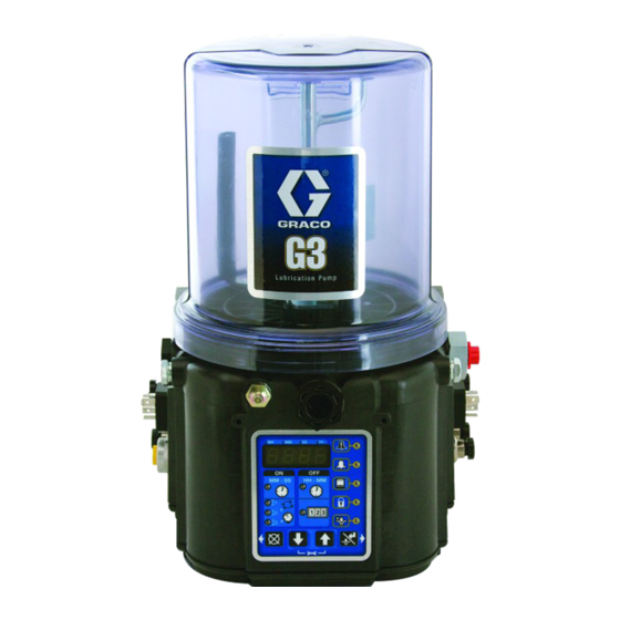
G3
One-Piece Automatic
Lubrication Pump
For dispensing of NLGI Grades #000 to #2 greases. For Professional Use Only.
Not approved for use in explosive atmospheres or hazardous (classified) locations.
Models, see page 3
5100 psi (35.1 MPa, 351.6 bar) Maximum Pump Output Pressure
Important Safety Instructions
Read all warnings and instructions in this
manual before using this equipment. Save
these instructions.
3A6319E
EN
Advertisement
Table of Contents

Related Manuals for Graco G3-G-24NC-8LTA00-0D00L000


Summary of Contents for Graco G3-G-24NC-8LTA00-0D00L000
- Page 1 Instructions ™ One-Piece Automatic Lubrication Pump 3A6319E For dispensing of NLGI Grades #000 to #2 greases. For Professional Use Only. Not approved for use in explosive atmospheres or hazardous (classified) locations. Models, see page 3 5100 psi (35.1 MPa, 351.6 bar) Maximum Pump Output Pressure Important Safety Instructions Read all warnings and instructions in this manual before using this equipment.
-
Page 2: Table Of Contents
Graco Standard Warranty ....24 Graco Information ..... . . 24... -
Page 3: Part / Model Numbers
The Part Number is a six-digit unique number that is only used to order the G3 Pump. Directly related to this six- digit Part Number is the configured Graco Model Number. This configured number identifies the distinct features of a specific G3 Pump. To help with understanding each component that makes up the Model Number, see Under- standing the Model Number, page 4. -
Page 4: Understanding The Model Number
Use the Code Sample provided below to identify each component’s location in the Model Number. The options for each component that make up the code are provided on the lists below. NOTE: Some pump configurations are not available. Contact Graco Customer Service or your local Graco distribu- tor for assistance. -
Page 5: Warnings
Warnings Warnings The following warnings are for the setup, use, grounding, maintenance, and repair of this equipment. The exclama- tion point symbol alerts you to a general warning and the hazard symbols refer to procedure-specific risks. When these symbols appear in the body of this manual or on warning labels, refer back to these Warnings. Product-spe- cific hazard symbols and warnings not covered in this section may appear throughout the body of this manual where applicable. - Page 6 Warnings WARNING EQUIPMENT MISUSE HAZARD Misuse can cause death or serious injury. • Do not operate the unit when fatigued or under the influence of drugs or alcohol. • Do not exceed the maximum working pressure or temperature rating of the lowest rated system component.
-
Page 7: Component Identification
Top Mounting Bracket Pressure Relief Valve (not shown. Not included / required for Bottom Mounting Bracket each outlet - Available from Graco. See Pressure Relief Part Number / Model Number example only shown, (see Valves, page 20.) pages 4, Understanding the Model Number, for details) -
Page 8: Typical Installation
Typical Installation Typical Installation Series Progressive Divider Valve Connected to fused power source Pressure Relief Valve (not included; required for each outlet - user supplied) Supply Hose (user supplied) Series Progressive Divider Valves To lube points Proximity Switch 3A6319E... -
Page 9: Injector Installations
Connected to fused power source Pressure Relief Valve (not included; required for each outlet - user supplied) Supply Hose (user supplied) Injectors To lube points Pressure Switch Vent Valve (not included / available from Graco. Parts, page 18.) Return to reservoir 3A6319E... -
Page 10: Installation
Insert (user supplied) spacers if there is still a gap The pump module was carefully packaged for shipment after adjusting the bracket. by Graco. When the package arrives, perform the fol- lowing procedure to unpack the units: 1. Inspect the shipping box carefully for shipping damage. -
Page 11: Wiring And Installation Diagrams
Installation Wiring and Installation Diagrams The table identifies the wiring and installation diagrams for the cable included with the pump. Low Level Outputs See Low Level Output Option, page 15 for functional description. See Dimensions, page 21 for ratings. Power DIN DC - 15 foot Pins (F . -
Page 12: Setup
• Install a pressure relief valve close to every pump outlet; before any auxiliary fitting. NOTE: A pressure relief valve can be purchased from Graco. 3A6319E... -
Page 13: Setting Pump Outlet Volume
Pressure Relief Procedure, page 12. with setting the ON time of the pump allows for control of the output volume. • Only use Graco supplied spacers to control output • Use these volume adjustments as a starting point volume. -
Page 14: Prime The Pump
Setup Prime the Pump 4. Continue filling until the follower plate reaches the Max label, which is slightly lower than the vent port . 10). NOTE: It is not necessary to prime the pump every time it is filled with lubricant. The pump only requires priming the first time it is used or if it is allowed to run dry. -
Page 15: Operation
Pump ON (Run) time. If alternative reached a low level to the controller. ON / OFF times are required, contact Graco Cus- tomer Service for assistance. To ensure that a low level condition has been met, three (3) or more low level triggers must be detected within one (1) minute or less. -
Page 16: Maintenance
Maintenance Maintenance Frequency Component Required Maintenance Daily and at refill Zerk Fittings Keep all fittings clean using a clean dry cloth. Dirt and debris can dam- age pump and lubrication system. Daily G3 Pump Unit and Reservoir Keep pump unit and reservoir clean using a clean dry cloth. -
Page 17: Troubleshooting
Ensure vent port is not plugged. Lubricant leaks past seal located on filling the bottom of the reservoir If problem persists, contact Graco Customer Service or your local Graco distributor for assistance. Unit not pumping during ON cycle, Failed motor Replace unit. -
Page 18: Parts
Parts Parts 8 Liter Model Reservoir for 12 Liter and Larger Models (See 8 Liter Model for all other parts) 3A6319E... -
Page 19: Part No./Description
Part No./Description Part No./Description Fuses Part Description Qty. BASE, three pump housing Part Description Qty. SCREW< cap, hex head 571040 FUSE, 24 volt DC RING, snap COVER 17S695 SEAL, reservoir BRACKET, top RESERVOIR, 8L RESERVOIR, 12L RESERVOIR, 15L RESERVOIR, 20L SLEEVE (12L and larger, only) ROD, support, 8L ROD, support, 12L... -
Page 20: Pressure Relief Valves
Part No./Description Pressure Relief Valves Installation and Repair Kits Important Information regarding Pressure Relief Valve Manual 16C807. Kit No. Description Number 571026 KIT, output union, 3 pump 3A0523 ◆ Pressure Relief Valve 16C807 can only be used on the G3 pump. It is not intended for use with any other 571063 KIT, output union, 2 pump products. -
Page 21: Dimensions
Dimensions Dimensions Height Width Depth Model Inches Inches Inches 22.34 56.74 8.94 22.70 10.37 26.34 27.34 69.44 8.94 22.70 10.37 26.34 30.99 78.71 8.94 22.70 10.37 26.34 37.09 94.21 8.94 22.70 10.37 26.34 Mounting Bracket Dimensions Model Inches 16.22 412.0 21.22 539.0 24.87... -
Page 22: Technical Specifications
Technical Specifications Technical Specifications G3 One-Piece Automatic Lubrication Pump Metric Pump Output Pressure 5100 psi 35.1 MPa, 351.6 bar Power 24 VDC 18 - 30 VDC; 2.5 A current, 60 W, inrush/locked rotor 6 A Outputs - Low Level (Dry Contact) Contact Rating 10 Watts Maximum Switch Rating... -
Page 23: California Proposition 65
California Proposition 65 California Proposition 65 CALIFORNIA RESIDENTS WARNING: Cancer and reproductive harm – www.P65warnings.ca.gov. 3A6319E... -
Page 24: Graco Standard Warranty
With the exception of any special, extended, or limited warranty published by Graco, Graco will, for a period of twelve months from the date of sale, repair or replace any part of the equipment determined by Graco to be defective.
Need help?
Do you have a question about the G3-G-24NC-8LTA00-0D00L000 and is the answer not in the manual?
Questions and answers