PairGain HiGain HLU-319 Manual
Hide thumbs
Also See for HiGain HLU-319:
- Manual (72 pages) ,
- Quick installation manual (20 pages) ,
- Manual (64 pages)
Table of Contents
Advertisement
Quick Links
PAIRGAIN TECHNOLOGIES
Technical Practice
Engineering - PLANT Series
P
AIR
List 2D, PairGain #150-1140-24, CLEI Code: T1L1BH03AA
CONTENTS
A. PRODUCT OVERVIEW
(Doubler and Non-Doubler)
19. LOOPBACK OPERATION
20. TESTING
21. SYSTEM MAINTENANCE MENU
SCREENS
G
T
AIN
ECHNOLOGIES
MODEL HLU-319
H
G
I
PAGE
2
2
3
5
7
11
12
12
12
13
13
14
14
14
16
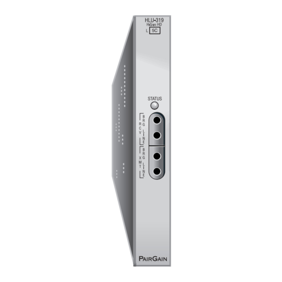
Figure 1. HLU-319, List 2D Front Panel. The PairGain
HLU-319 is the local unit used in conjunction with the HRU-
29
412 remote unit to provide a complete HiGain HDSL
system.
37
37
38
This product incorporates static sensitive
40
components. Proper electrostatic discharge
51
Section 150-319-124
L
U
TM
AIN
INE
NIT
CAUTION
procedures must be followed.
Revision 03
November 6, 1996
Page 1
Advertisement
Table of Contents

Subscribe to Our Youtube Channel
Related Manuals for PairGain HiGain HLU-319


Summary of Contents for PairGain HiGain HLU-319
-
Page 1: Table Of Contents
12. SECTION INTRODUCTION 13. POWER CONSUMPTION 14. LOOPBACK OPERATION 15. TESTING Figure 1. HLU-319, List 2D Front Panel. The PairGain 16. SYSTEM MAINTENANCE MENU HLU-319 is the local unit used in conjunction with the HRU- SCREENS 412 remote unit to provide a complete HiGain HDSL C. -
Page 2: Description And Features
1. DESCRIPTION AND FEATURES doubler and HRU-412 1.01 PairGain’s HiGain Line Unit Model HLU-319 • Optional bipolar (± 65 or ± 100 Vdc) or Issue 1, List 2D (see Figure 1) is the Central Office unipolar (-130 or -200 Vdc) HDSL line side of a repeaterless T1 transmission system. -
Page 3: Functional Operation
HLU-319, List 2D arbitrarily defines a frame bit. Figure 2. HLU-319, List 2D Block Diagram. PairGain’s HDSL technology provides full duplex services at standard T-1 rates over copper wires between an HLU and an HRU, which comprise one HiGain system. - Page 4 Section 150-319-124 Revision 03 3.08. The HLU-319, List 2D contains two separate 3.04 The received HDSL channels are processed by the transceiver and then passed on to the HLU- power converters. The main power supply converts 319, List 2D demultiplexer module. The demultiplexer -48 Vdc local battery to logic power for the HLU-319, List 2D circuits.
-
Page 5: Alarms
Section 150-319-124 Revision 03 flashes red for the duration of a minor alarm condition. 4. ALARMS Alarms 4 and 5 can be inhibited by selecting “None” 4.01 Pin H is the HLU-319 minor alarm (MNRALM) for the ESAL system option (see Section 5 for System output pin, which replaces the Local Loss of Signal Settings information). - Page 6 Section 150-319-124 Revision 03 Figure 3. DB-9 RS-232 I/O Pin-Outs. A standard RS-232 (DB-9, female) connector on the front panel provides access to the menu interface feature via a RS-232 terminal. Figure 4. HLU-319, List 2D Card-Edge Connectors. The active pins are highlighted in black in the above illustration. Page 6...
-
Page 7: System Options
Section 150-319-124 Revision 03 5.04 Pressing the Mode button for three or more 5. SYSTEM OPTIONS seconds causes the display to scroll through the HLU- 5.01 The HLU-319, List 2D contains a non-volatile 319, List 2D software version number, its list number, RAM (NVRAM) which stores the system options the type of frame pattern being received from the settings. - Page 8 Section 150-319-124 Revision 03 5.07 The Circuit ID option is set by choosing the 5.11 The new T1 transceiver chip in the List 2D H option from the terminal Main Menu screen (see allows the unit to process both B8ZS and AMI code Figure 7 for non-doubler applications and Figure 16 inputs, regardless of the DS1 code setting (AMI or for doubler applications).
- Page 9 Section 150-319-124 Revision 03 TABLE 1. HLU-319, LIST 2D SYSTEM OPTIONS Note: An asterisk (*) indicates HLU-319, List 2D factory (default) settings. Mode Selection Description Sets the equalizer to DSX-1 for 0 to 132 feet. Sets the equalizer to DSX-1 for 133 to 265 feet. Sets the equalizer to DSX-1 for 266 to 398 feet.
- Page 10 Section 150-319-124 Revision 03 TABLE 1. HLU-319, LIST 2D SYSTEM OPTIONS (CONTINUED) Mode Selection Description AUTO The HLU-319, List 2D and HRU-412 independently monitor their incoming T1 bit streams for the Binary Eight Zero Substitution (B8ZS) pattern. If either unit detects this pattern, it enters its B8ZS mode.
-
Page 11: Hdsl Line Voltage Option
Section 150-319-124 Revision 03 6. HDSL LINE VOLTAGE OPTION 6.03 The bipolar selection sets the HDSL line voltage to +65 V on loop 2 and -65 V on loop 1, for 6.01 The symmetry of the HDSL line powering non-doubler applications. Doubler applications will voltage can be set by the S2 switch, located on the have +100 V on loop 2 and -100 V on loop 1. -
Page 12: Installation
14 Watts (without doubler); 25 Watts (with doubler) extent of damage to the transportation company and Maximum Heat Dissipation to PairGain Technologies. 6 Watts (without doubler); 9 Watts (with doubler) 7.02 The HLU-319 mounts in the group of both... -
Page 13: Warranty
PairGain Technologies warrants this product 11.01 PairGain Technical Assistance is available 24 hours a day, 7 days a week by contacting PairGain’s to be free of defects and fully functional for a period of 36 months from the date of original shipment, given Customer Service Engineering group at one of the proper installation. -
Page 14: Applications Without Higain
Section 150-319-124 Revision 03 13.03 In Central Office locations, the maximum B. APPLICATIONS WITHOUT HIGAIN DOUBLERS (HDU-451) power dissipation for open-faced, natural convection cooled mountings is limited to 120 Watts/sq. ft. per 12. SECTION INTRODUCTION Section 4.2.3 of the NEBS standard TR-NWT-000063. The footprint of a standard 28-slot 23-inch HLU-319, 12.01 This section addresses HLU-319, List 2D... - Page 15 5 seconds before the HiGain the additional (1 in 6) Smart-Jack loopback command. system responds. Table 2 lists the test procedures Refer to the PairGain HiGain-2 Intelligent Repeater that apply when using the GNLB mode. Application Note #910 Part #325-910-100 for more SPLB details.
-
Page 16: Testing
Section 150-319-124 Revision 03 15. TESTING 14.09 Pressing both the Mode and SEL front panel push buttons, for at least three seconds, initiates a 15.01 Table 2 through Table 7 provide step-by-step Manual Loopback session. This session allows the test procedures for the HLU-319, List 2D as a function user to select one of four HiGain system loopbacks. - Page 17 Section 150-319-124 Revision 03 Figure 6. HLU-319, List 2D Non-Doubler Loopback Configurations. The most important of the HiGain family of loopback options is the Smart-Jack loopback, which emulates the functions of a standard NID. Page 17...
- Page 18 Section 150-319-124 Revision 03 TABLE 2. HLU-319 GNLB TEST PROCEDURES Step Action Have the CO tester send the HRU-412 (3 in 7) in-band loop-up code for five seconds. Observe that the HLU-319, List 2D displays the “NREM” message indicating an HRU loopback is in effect (see Figure 6).
- Page 19 Section 150-319-124 Revision 03 TABLE 3. HLU-319 A1LB TEST PROCEDURES Step Action Send the in-band Arming and NI LPBK code 11000 into the HLU-319, List 2D, for at least five seconds or at least four repetitions of the 16-bit ESF data link Arming code 1111 1111 0100 1000 (FF48).
- Page 20 Section 150-319-124 Revision 03 TABLE 3. TEST PROCEDURES FOR A1LB OPTION (CONTINUED) Step Action Using the following codes, a network tester can activate loopbacks NLOC or NREM or SMJK (if ENAbled) (see Figure 6). A customer tester can activate loopbacks CLOC or CREM. ADDRESSABLE 1 (A1LB) REPEATER LOOPBACK COMMANDS ARMING or NI LPBK (in-band) Arming code...
- Page 21 Section 150-319-124 Revision 03 TABLE 4. HLU-319 A2LB TEST PROCEDURES Step Action Send the in-band Arming and NI LPBK code 11000 into the HLU-319, List 2D, for at least five seconds or at least four repetitions of the 16-bit ESF data link Arming code 1111 1111 0100 1000 (FF48).
- Page 22 Section 150-319-124 Revision 03 TABLE 4. HLU-319 A2LB TEST PROCEDURES (CONTINUED) Step Action Using the following codes, a network tester can activate loopbacks NLOC or NREM or SMJK (if ENAbled) (see Figure 6). A customer tester can activate loopbacks CLOC or CREM. ADDRESSABLE 2 (A2LB) REPEATER LOOPBACK COMMANDS ARMING or NI LPBK (in-band) Arming code...
- Page 23 Section 150-319-124 Revision 03 TABLE 5. HLU-319 A3LB TEST PROCEDURES Step Action The HiGain Line Unit can be looped back (NLOC in Figure 6) by sending the Addressable Office Repeater (AOR) LPBK activation code 1111 1111 0001 1110 (FF1E) for at least five seconds.
- Page 24 Section 150-319-124 Revision 03 TABLE 6. HLU-319 A4LB TEST PROCEDURES Step Action The HiGain Line Unit can be looped back (NLOC in Figure 6) by sending the Addressable Office Repeater (AOR) LPBK activation code 1111 1111 0001 1110 (FF1E) for at least five seconds.
- Page 25 Section 150-319-124 Revision 03 TABLE 7. HLU-319 A5LB TEST PROCEDURES Step Action Send the in-band Arming and NI (Network Interface) LPBK code 11000 into the HLU-319, List 2D, for at least five seconds or at least four repetitions of the 16-bit ESF data link Arming code 1111 1111 0100 1000 (FF48).
- Page 26 Section 150-319-124 Revision 03 TABLE 7. HLU-319 A5LB TEST PROCEDURES (CONTINUED) Step Action Using the following codes, a network tester can activate loopbacks NLOC or NREM or SMJK (if ENAbled) (see Figure 6). A customer tester can activate loopbacks CLOC or CREM. ADDRESSABLE 5 (A5LB) REPEATER LOOPBACKS ARMING or NI LPBK (in-band) Arming code...
- Page 27 Section 150-319-124 Revision 03 TABLE 8. HLU-319, LIST 2D STATUS MENU MESSAGES Message Full Name Description ALARMS: NONE No Alarms “None” indicates no alarms. LLOS Local Loss of Signal No signal from HLU-319, List 2D local DSX-1 interface. RLOS Remote Loss of Signal No signal from HRU-412 remote DS1 interface.
- Page 28 Section 150-319-124 Revision 03 TABLE 8. HLU-319, LIST 2D STATUS MENU MESSAGES (CONTINUED) Message Full Name Description LOOPBACKS : SMJK Smart-Jack Loopback The loopback at HRU-412 (remote) toward network (see Figure 6) initiated by either the (2 in 5) in-band loopback code or the out-of-band ESF data link loopback code.
-
Page 29: System Maintenance Menu Screens
Section 150-319-124 Revision 03 16. SYSTEM MAINTENANCE MENU SCREENS 16.06 Figure 13 shows the 7-Day Performance History screen. “Errored Seconds” 16.01 Figure 7 is the Maintenance Terminal Main “Unavailable Seconds” for both HDSL loops and each Menu screen. Its eight sub-menus provide many of the two DS1 inputs are listed for the current and useful provisioning, test and monitoring tools. - Page 30 Section 150-319-124 Revision 03 TABLE 9. GLOSSARY OF HIGAIN TERMS Term Definition Margins Indicates the excess signal-to-noise ratio, at either the HRU-412 or HLU 319, List 2D HDSL ports, relative to a 10 Bit Error Rate. First value is current margin.
- Page 31 Section 150-319-124 Revision 03 TABLE 10. HLU-319, LIST 2D FOUR-CHARACTER FRONT PANEL MESSAGES Message Full Name Description CREM Customer Remote Loopback Signal from customer is looped back to customer at HLU-319. NLOC Network Local Loopback DSX-1 signal is looped back to DSX-1 at HLU. CLOC Customer Local Loopback Signal from customer is looped back to customer at HRU-412.
- Page 32 Section 150-319-124 Revision 03 TABLE 10. HLU-319, LIST 2D FOUR-CHARACTER FRONT PANEL MESSAGES (CONTINUED) Message Full Name Description PWR FEED SHRT Power Feed Short Indicates a short between the two HDSL pairs. This same message can occur with an HRU which is drawing the correct amount of power over good cable pairs, but can not communicate with the HLU.
- Page 33 Section 150-319-124 Revision 03 Figure 7. HLU-319, List 2D Main Menu. Figure 8. HLU-319, List 2D Non-Doubler Status Display. Page 33...
- Page 34 Section 150-319-124 Revision 03 Figure 9. HLU-319, List 2D Set Clock Menu. Figure 10. HLU-319, List 2D System Settings Menu. Page 34...
- Page 35 Section 150-319-124 Revision 03 Figure 11. HLU-319, List 2D Non-Doubler Loopback Menu Figure 12. HLU-319, List 2D Non-Doubler Performance Data Screen. Page 35...
- Page 36 Section 150-319-124 Revision 03 Figure 13. HLU-319, List 2D Non-Doubler 7-Day Performance History Screen. Figure 14. HLU-319, List 2D Non-Doubler Alarm History Screen. Page 36...
-
Page 37: Applications Using Higain Doublers (Hdu-451)
Section 150-319-124 Revision 03 APPLICATIONS USING HIGAIN DOUBLERS Lists 1, 2, 3, 3A, 4, and 5 can not be used, (HDU-451) Lists 6, 7, and greater can. 17. DOUBLER DEPLOYMENT RULES 4. The HRU-412 CPE current option must be set to 0 mA. Its 60 mA CPE current switch 17.01 For doubler applications, one or two doublers must be set to 0 mA, or, its card edge pins... - Page 38 Section 150-319-124 Revision 03 TABLE 11. HLU-319, LIST 2D POWER PARAMETERS WITH HDU-451 60 mA CPE CO Voltage CO Current Power HLU Power HDU-451 Current Volts Amps Consumption Dissipation Watts Doubler Models Watts 42.50 0.50 21.00 HDU-451, List 1-4 HDU-439/437 List 1 48.00 0.44 21.00...
- Page 39 • Initiation from either end and two in-line HDU-451 doublers. Refer to the • Repeating bit error signatures PairGain HiGain Intelligent Repeater Application Note • Alternate query loopback. #910, Part #325-910-100, for more SPLB details. These additions make A1LB identical to the A2LB, but 19.08...
- Page 40 Section 150-319-124 Revision 03 20. TESTING 19.09 The HiGain system may take longer than normal to respond to in-band loopback commands 20.01 Table 12 through Table 17 provide step-by- when its framing mode is set to UNFR and the in-band step test procedures for the HLU-319, List 2D as a commands are sent in either an SF or ESF mode.
- Page 41 Section 150-319-124 Revision 03 Figure 15. HLU-319 Doubler Loopback Configurations. The most important of the HiGain family of loopback options is the Smart-Jack loopback, which emulates the functions of a standard NID. Page 41...
- Page 42 Section 150-319-124 Revision 03 TABLE 12. HLU-319 GNLB TEST PROCEDURES Step Action Have the CO tester send the HRU-412 (3 in 7) in-band loop-up code for five seconds. Observe that the HLU-319, List 2D displays the “NREM” message indicating an HRU-412 loopback is in effect (see Figure 15).
- Page 43 Section 150-319-124 Revision 03 TABLE 13. HLU-319 A1LB TEST PROCEDURES Step Action Send the in-band Arming and NI LPBK code 11000 into the HLU-319, List 2D, for at least five seconds or at least four repetitions of the 16-bit ESF data link Arming code 1111 1111 0100 1000 (FF48). (Left bit arrives first.) Monitor the output of the HLU-319, List 2D for the return of the pattern.
- Page 44 Section 150-319-124 Revision 03 TABLE 13. HLU-319 A1LB TEST PROCEDURES (CONTINUED) Step Action Using the following codes, a network tester can activate loopbacks NLOC or NREM or SMJK (if ENAbled) (see Figure 15). A customer tester can activate loopbacks CLOC or CREM. ADDRESSABLE 1 (A1LB) REPEATER LOOPBACK COMMANDS ARMING or NI LPBK (in-band) Arming code...
- Page 45 Section 150-319-124 Revision 03 TABLE 14. HLU-319 A2LB TEST PROCEDURES Step Action Send the in-band Arming and NI LPBK code 11000 into the HLU-319, List 2D, for at least five seconds or at least four repetitions of the 16-bit ESF data link Arming code 1111 1111 0100 1000 (FF48). (Left bit arrives first.) Monitor the output of the HLU-319, List 2D for the return of the pattern.
- Page 46 Section 150-319-124 Revision 03 TABLE 14. HLU-319 A2LB TEST PROCEDURES (CONTINUED) Step Action Using the following codes, a network tester can activate loopbacks NLOC or NREM or SMJK (if ENAbled) (see Figure 15). A customer tester can activate loopbacks CLOC or CREM. ADDRESSABLE 2 (A2LB) REPEATER LOOPBACK COMMANDS ARMING or NI LPBK (in-band) Arming code...
- Page 47 Section 150-319-124 Revision 03 TABLE 15. HLU-319 A3LB TEST PROCEDURES Step Action The HLU-319, List 2D can be looped back (NLOC in Figure 15) by sending the Addressable Office Repeater (AOR) LPBK activation code 1111 1111 0001 1110 (FF1E) for at least five seconds. This causes the HLU-319, List 2D to enter its NLOC state (see Figure 15).
- Page 48 Section 150-319-124 Revision 03 TABLE 16. HLU-319 A4LB TEST PROCEDURES Step Action The HLU-319, List 2D can be looped back (NLOC in Figure 15) by sending the Addressable Office Repeater (AOR) LPBK activation code 1111 1111 0001 1110 (FF1E)for at least five seconds. This causes the HLU-319, List 2D to enter its NLOC state (see Figure 15).
- Page 49 Section 150-319-124 Revision 03 TABLE 17. HLU-319 A5LB TEST PROCEDURES Step Action Send the in-band Arming and NI LPBK code 11000 into the HLU-319, List 2D, for at least five seconds or at least four repetitions of the 16-bit ESF data link Arming code 1111 1111 0100 1000 (FF48). (Left bit arrives first.) Monitor the output of the HLU-319, List 2D for the return of the pattern.
- Page 50 Section 150-319-124 Revision 03 TABLE 17. HLU-319 A5LB TEST PROCEDURES (CONTINUED) Step Action Using the following codes, a network tester can activate loopbacks NLOC or NREM or SMJK (if ENAbled) (see Figure 15). A customer tester can activate loopbacks CLOC or CREM. ADDRESSABLE 5 (A5LB) REPEATER LOOPBACK COMMANDS ARMING or NI LPBK (in-band) Arming code...
- Page 51 Section 150-319-124 Revision 03 21.07 Figure 24 through Figure 27 show the 21. SYSTEM MAINTENANCE MENU SCREENS Performance Data screens for doubler applications. 21.01 Figure 16 is the Maintenance Terminal Main The “Errored Seconds” and “Unavailable Seconds” for Menu screen. Its eight sub-menus provide many both HDSL loops and each T1 input are listed at 15- useful provisioning, test and monitoring tools.
- Page 52 Section 150-319-124 Revision 03 21.09 Figure 32 through Figure 34 show the Alarm lists the number of times each alarm occurred. All the History screens for doubler applications. The alarms data can be cleared by pressing C (Clear). are defined in Section A Paragraph 4.01. The LOS maximum non-overflowing count is 999.
- Page 53 Section 150-319-124 Revision 03 TABLE 18. HLU-319, LIST 2D STATUS MENU MESSAGES (CONTINUED) Message Full Name Description LOOPBACKS: SMJK Smart-Jack Loopback The loopback at HRU-412 (remote) toward network (see Figure 15) initiated by either the (2 in 5) in-band loopback code or the out-of-band ESF data link loopback code.
- Page 54 Section 150-319-124 Revision 03 TABLE 19. GLOSSARY OF HIGAIN TERMS Term Definition Margins Indicates the excess signal-to-noise ratio, at the HRU-412, HDU-451, or HLU- 319, List 2D HDSL ports, relative to a 10 BER. First value is current margin. Second value is minimum margin since (C)leared last. Third value is maximum value since cleared.
- Page 55 Section 150-319-124 Revision 03 TABLE 20. HLU-319, LIST 2D FOUR-CHARACTER FRONT PANEL MESSAGES Message Full Name Description CREM Customer Remote Loopback Signal from customer is looped back to customer at HLU- 319. NLOC Network Local Loopback DSX-1 signal is looped back to DSX-1 at HLU. CLOC Customer Local Loopback Signal from customer is looped back to customer at HRU-...
- Page 56 Section 150-319-124 Revision 03 TABLE 20. HLU-319, LIST 2D FOUR-CHARACTER FRONT PANEL MESSAGES (CONTINUED) Message Full Name Description A2L1 Acquisition 2 Loop 1 The first doubler is trying to establish synchronization with either the HRU or the second doubler multiplexers on loop 1 of span 2.
- Page 57 Section 150-319-124 Revision 03 TABLE 20. HLU-319, LIST 2D FOUR-CHARACTER FRONT PANEL MESSAGES (CONTINUED) Message Full Name Description BAD RT? No response from HRU The HLU does not receive any response from the HRU. Thus, the HRU’s integrity is questionable. VER XXXX HLU software Version number This is displayed during the System Settings review...
- Page 58 Section 150-319-124 Revision 03 Figure 16. HLU-319, List 2D Main Menu. Figure 17. HLU-319, List 2D Status Display - Span 1 (1 or 2 Doublers). Page 58...
- Page 59 Section 150-319-124 Revision 03 Figure 18. HLU-319, List 2D Status Display - Span 2 (1 Doubler). Figure 19. HLU-319, List 2D Status Display - Span 2 (2 Doublers). Page 59...
- Page 60 Section 150-319-124 Revision 03 Figure 20. HLU-319, List 2D Status Display - Span 3 (2 Doublers). Figure 21. HLU-319, List 2D Set Clock Menu. Page 60...
- Page 61 Section 150-319-124 Revision 03 Figure 22. HLU-319, List 2D System Settings Menu. Figure 23. HLU-319, List 2D Doubler Loopback Menu. Page 61...
- Page 62 Section 150-319-124 Revision 03 Figure 24. HLU-319, List 2D Performance Data Screen - Span 1 (1 or 2 Doublers). Figure 25. HLU-319, List 2D Performance Data Screen - Span 2 (1 Doubler). Page 62...
- Page 63 Section 150-319-124 Revision 03 Figure 26. HLU-319, List 2D Performance Data Screen - Span 2 (2 Doublers). Figure 27. HLU-319, List 2D Performance Data Screen - Span 3 (2 Doublers Page 63...
- Page 64 Section 150-319-124 Revision 03 Figure 28. HLU-319, List 2D 7-Day Performance History Screen - Span 1 (1 or 2 Doublers). Figure 29. HLU-319, List 2D 7-Day Performance History Screen - Span 2 (1 Doubler). Page 64...
- Page 65 Section 150-319-124 Revision 03 Figure 30. HLU-319, List 2D 7-Day Performance History Screen - Span 2 (2 Doublers). Figure 31. HLU-319, List 2D 7-Day Performance History Screen - Span 3 (2 Doublers). Page 65...
- Page 66 Section 150-319-124 Revision 03 Figure 32. HLU-319, List 2D Alarm History Screen - Span 1 (1 or 2 Doublers). Figure 33. HLU-319, List 2D Alarm History Screen - Span 2 (1 or 2 Doublers). Page 66...
- Page 67 Section 150-319-124 Revision 03 Figure 34. HLU-319, List 2D Alarm History Screen - Span 3 (2 Doublers). Copyright © 1996, PairGain Technologies, Inc. PairGain is a registered trademark, CopperOptics and HiGain are trademarks of PairGain Technologies, Inc. Page 67...
Need help?
Do you have a question about the HiGain HLU-319 and is the answer not in the manual?
Questions and answers